How does it work?
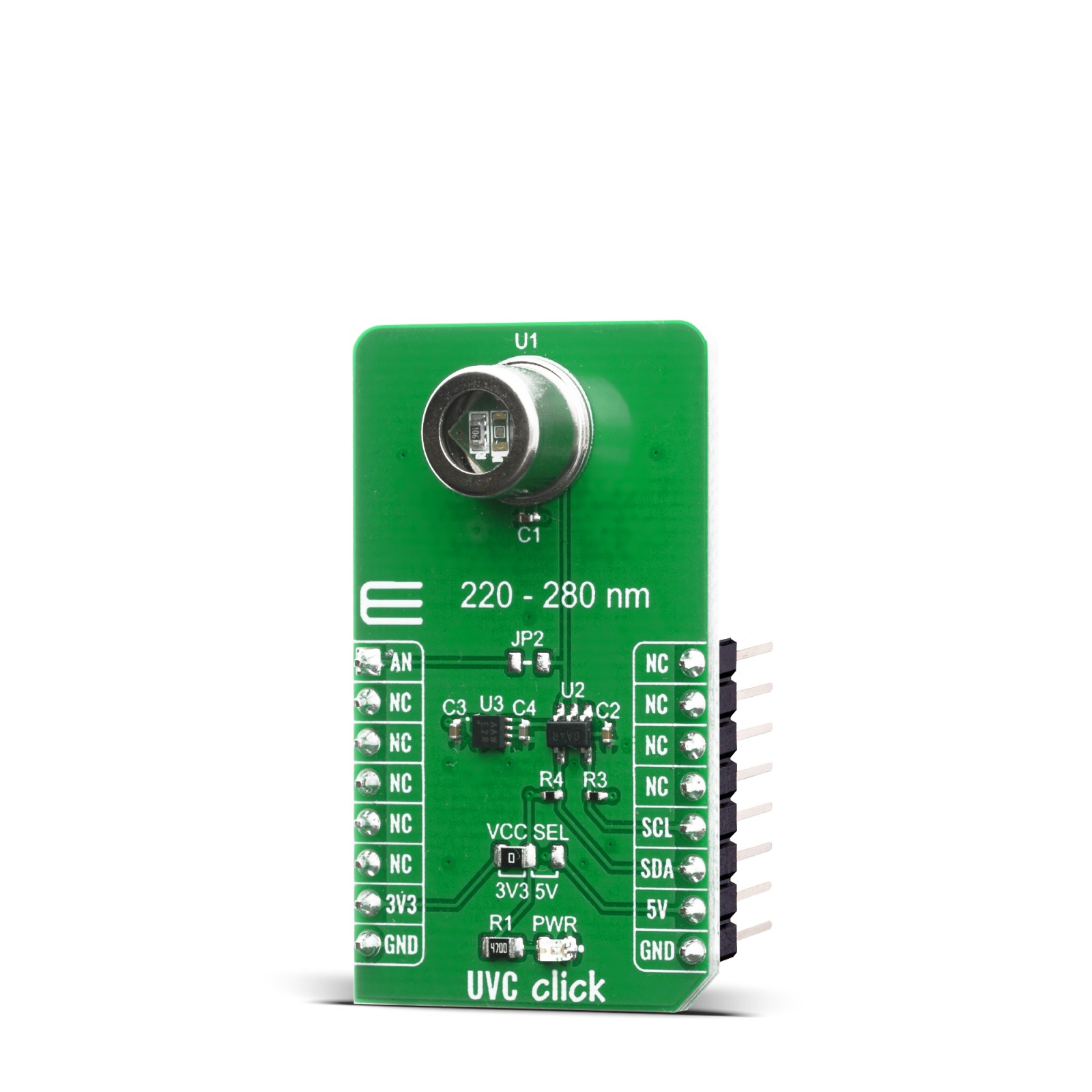
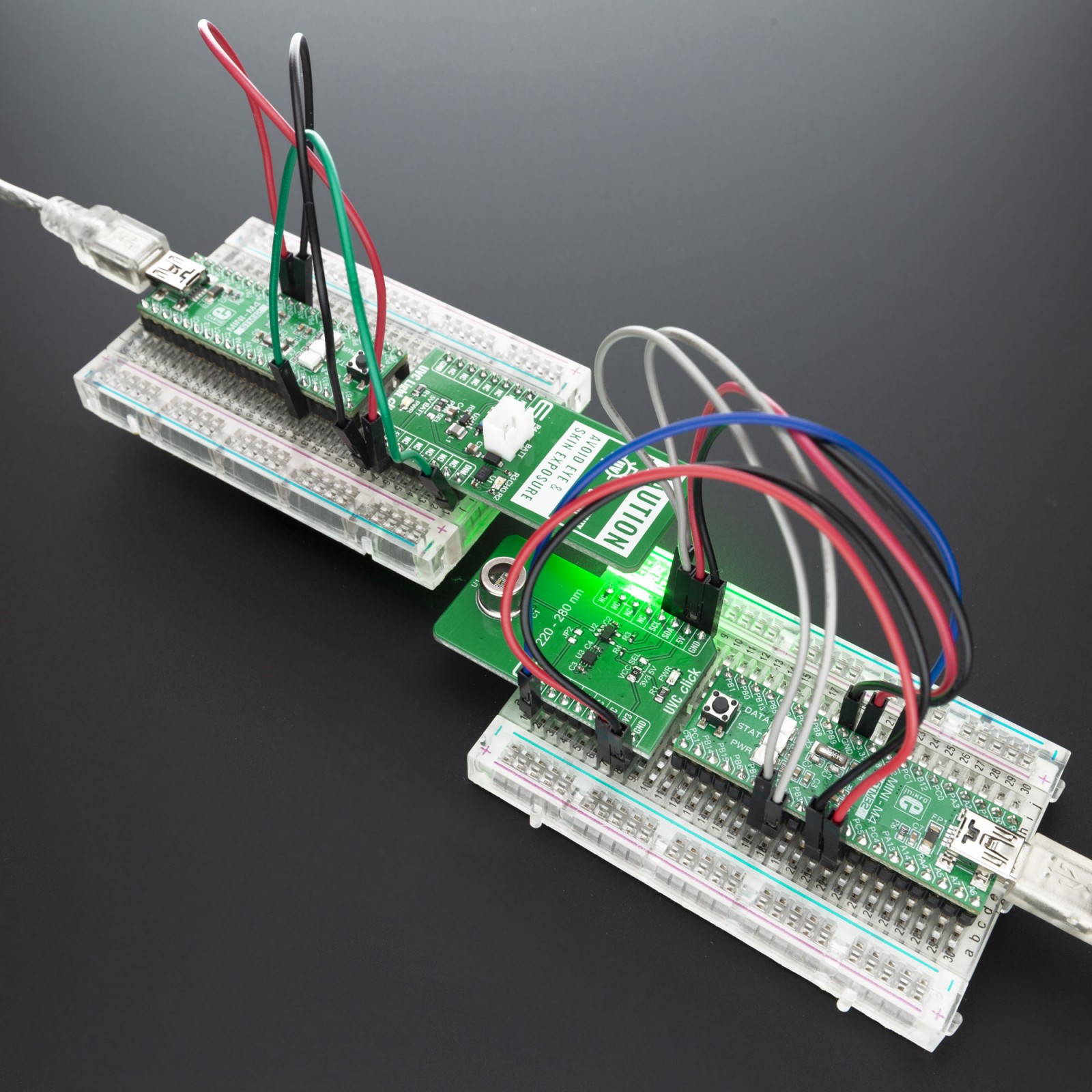
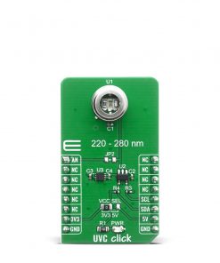
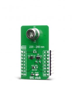
UVC Click can provide reliable and stable UVC light intensity value by using GUVC-T21GH sensor which have spectral detection range of 220nm – 280nm with output responsivity of 0.6mV/nW (at 254nm). Light intensity is converted in digital value by using MCP3221 a successive approximation A/D converter (ADC) with a 12-bit resolution.
Communication to the MCP3221 is performed using a 2-wire, I2C compatible interface. Standard (100 kHz) and Fast (400 kHz) I2C modes are available with the device. An on-chip conversion clock enables independent timing for the I2C and conversion clocks.
To get reliable readings from sensor, ADC power and voltage reference is supplied from MCP1501T-33E/RW a buffered voltage reference with 3.3V output capable of sourcing up to 20mA of current as a low-drift bandgap-based reference. The bandgap uses chopper-based amplifiers, effectively reducing the drift to zero.
Second way of reading output voltage from sensor is by placing 0 ohm resistor on JP2 position labeled on PCB and reading analog value from AN pin on mikroBUS™. This way you can relay on external voltage reference and ADC with some other desired specifications for your application and you can measure light power intensity up to 14.1 mW/cm².
An SMD jumper labeled as VCC SEL can be moved to the desired position, allowing both 3.3V and 5V MCUs to be used with this Click board™.
Specifications
Type
Optical,UVC Light
Applications
It can be used for UV measurement applications, sterilization lamp monitoring, prototyping of wearables, handsets, and various consumer electronics based on received UV light
On-board modules
GUVC-T21GH
Key Features
UVC sensing with 12-bit resolution, High Sensitivity, Good Solar Blindness
Interface
Analog,I2C
Feature
No ClickID
Compatibility
mikroBUS™
Click board size
M (42.9 x 25.4 mm)
Input Voltage
3.3V or 5V
Pinout diagram
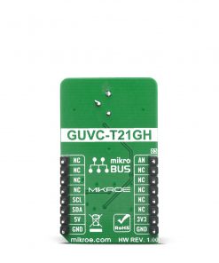
This table shows how the pinout on UVC Click corresponds to the pinout on the mikroBUS™ socket (the latter shown in the two middle columns).
Onboard settings and indicators
Label | Name | Default | Description |
---|---|---|---|
PWR | LD1 | – | Power LED Indicator |
VCC SEL | JP1 | Left | Logic level voltage selection: left position 3V3, right position 5V |
JP2 | Jumper | NP | Jumper for direct analog voltage reading from sensor |
Technical specification
Characteristic | Value |
---|---|
UVC sensing resolution | 12-bit |
Responsivity | 0.6mV/nW |
Spectral Detection Range | 220nm – 280nm |
Software Support
We provide a library for the UVC Click on our LibStock page, as well as a demo application (example), developed using MikroElektronika compilers. The demo can run on all the main MikroElektronika development boards.
Library Description
The library contains basic functions for working with the UVC click.
Key functions:
uint16_t uvc_read_raw_data( )
– Read 12bit raw datafloat uvc_get_voltage( )
– Calculate voltagefloat uvc_calculate_power( float voltage )
– Calculate power
Examples description
The application is composed of three sections :
- System Initialization – Initializes I2C module
- Application Initialization – Initializes driver init
- Application Task – Reads sensor raw data and calculating voltage and power data.
void application_task ( ) { uint16_t raw_data; float voltage; float power; char demo_text[ 20 ]; raw_data = uvc_read_raw_data(); IntToStr( raw_data, demo_text ); mikrobus_logWrite( "Raw data: ", _LOG_TEXT ); mikrobus_logWrite( demo_text, _LOG_LINE ); voltage = uvc_get_voltage(); FloatToStr( voltage, demo_text ); mikrobus_logWrite( "Voltage: ", _LOG_TEXT ); mikrobus_logWrite( demo_text, _LOG_TEXT ); mikrobus_logWrite( " mV", _LOG_LINE ); power = uvc_calculate_power( voltage ); FloatToStr( power, demo_text ); mikrobus_logWrite( "Power: ", _LOG_TEXT ); mikrobus_logWrite( demo_text, _LOG_TEXT ); mikrobus_logWrite( " mW/cm2", _LOG_LINE ); mikrobus_logWrite( "----------------------", _LOG_LINE ); Delay_ms( 1500 ); }
The full application code, and ready to use projects can be found on our LibStock page.
Other mikroE Libraries used in the example:
- I2C library
- Conversions
Additional notes and informations
Depending on the development board you are using, you may need USB UART click, USB UART 2 click or RS232 click to connect to your PC, for development systems with no UART to USB interface available on the board. The terminal available in all MikroElektronika compilers, or any other terminal application of your choice, can be used to read the message.
mikroSDK
This Click board™ is supported with mikroSDK – MikroElektronika Software Development Kit. To ensure proper operation of mikroSDK compliant Click board™ demo applications, mikroSDK should be downloaded from the LibStock and installed for the compiler you are using.
For more information about mikroSDK, visit the official page.