How does it work?
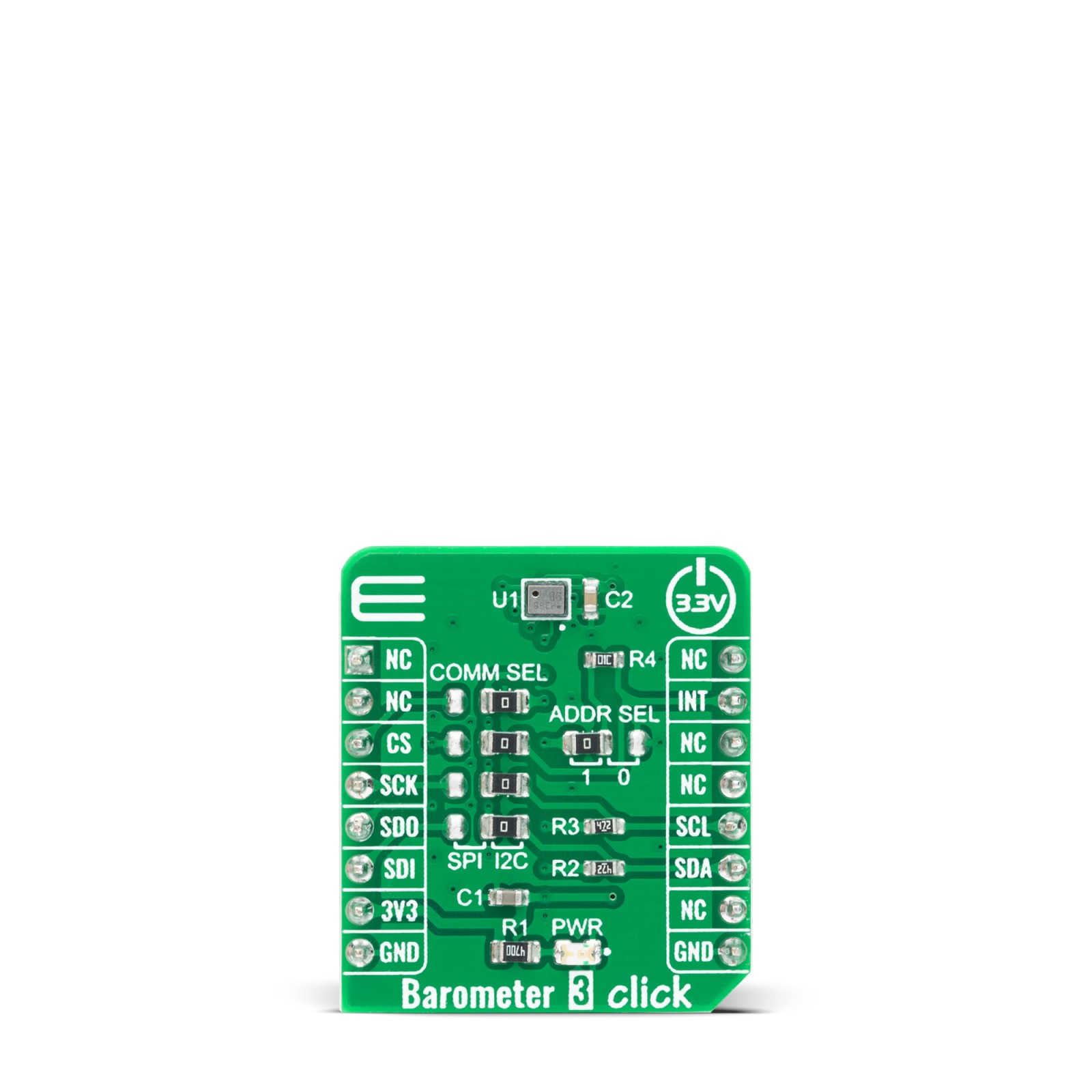
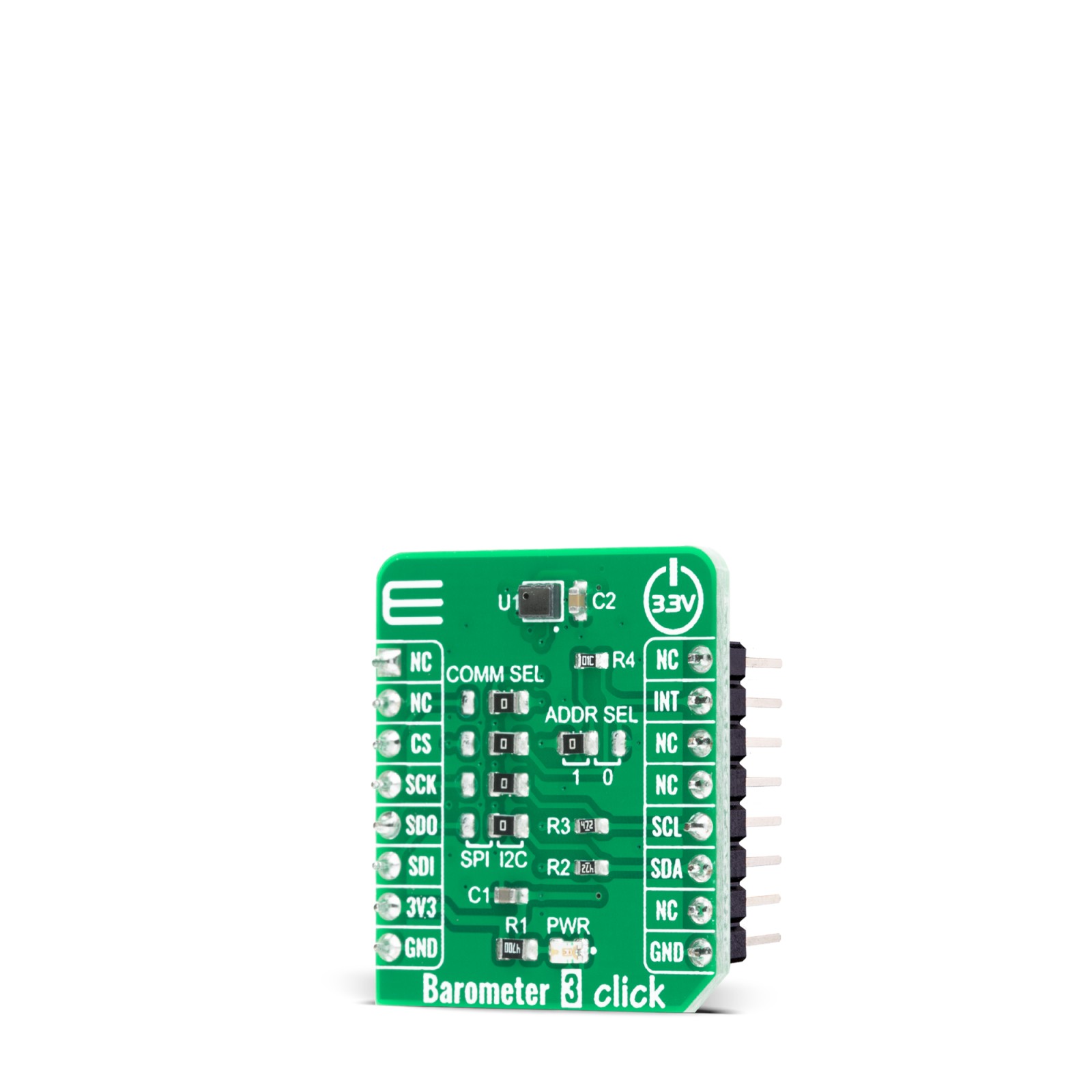
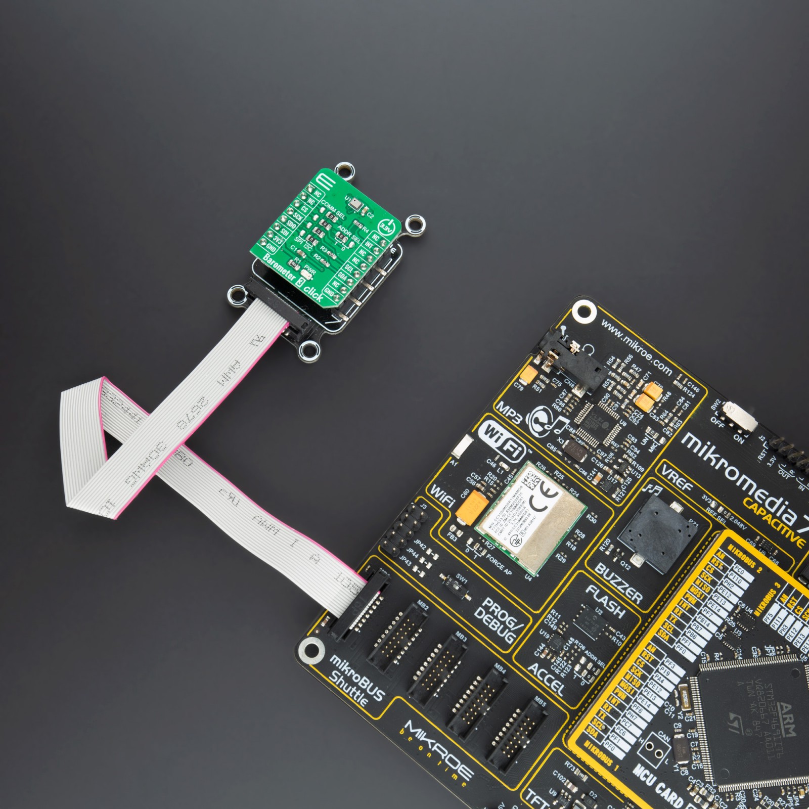
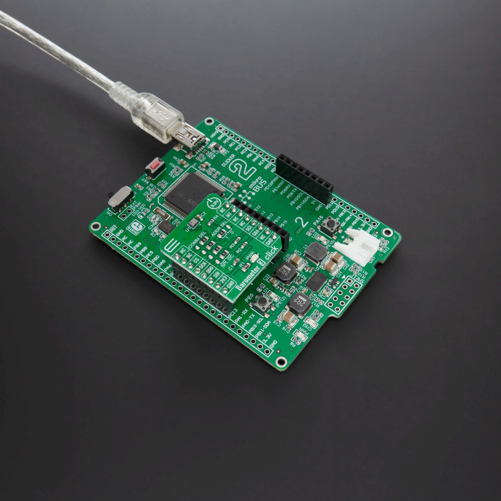
Barometer 3 Click is based on DPS368, a digital barometric air pressure sensor IC from Infineon. This Click board™ is capable of measuring both pressure and temperature based on a capacitive sensing principle which guarantees high precision during temperature changes. The internal signal processor converts the output from the pressure and temperature sensor elements to 24-bit results. Each unit is individually calibrated, the calibration coefficients calculated during this process are stored in the calibration registers. Sensor measurements and calibration coefficients are available through the serial I2C or SPI interface.
The sensor on the Barometer 3 Click boasts exceptional accuracy and precision, making it ideal for high-resolution atmospheric pressure measurements. In high precision mode, it offers a pressure sensor precision of ± 0.002 hPa, which corresponds to an altitude accuracy of ± 0.02 meters. Additionally, it provides a relative accuracy of ± 0.06 hPa, equivalent to ± 0.5 meters, and an absolute accuracy of ± 1 hPa, or ± 8 meters. These characteristics ensure reliable and precise readings in a wide range of applications.
The DPS368 sensor supports 3 different modes of operation: Standby, Command, and Background mode. Standby Mode represents default mode after Power-On or Reset where no measurements are performed. Command Mode means that one temperature or pressure measurement is performed according to the selected precision. In this mode, the sensor will return to Standby Mode when the measurement is finished, and the measurement result will be available in the data registers. Background Mode is a mode where pressure and/or temperature measurements are performed continuously according to the selected measurement precision and rate. The temperature measurement is performed immediately after the pressure measurement. The FIFO can be used to store 32 measurement results and minimize the number of times the sensor must be accessed to read out the results.
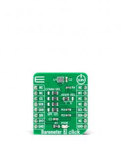
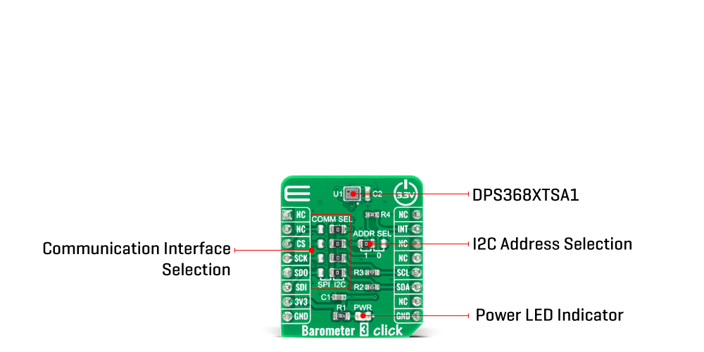
Barometer 3 Click offers a choice between two communication interfaces: I2C and SPI, with optional interrupt for I2C. The selection can be done by positioning SMD jumpers labeled as COMM SEL to an appropriate position. Note that all the jumpers for communication selection must be placed to the same side, or else the Click board™ may become unresponsive. When the I2C interface is selected, the DPS368 allows the choice of the least significant bit (LSB) of its I2C slave address. This can be done by using the SMD jumper labeled as ADDR SEL and the default address of sensor is set to 0x77.
This Click board™ uses both I2C and SPI communication interfaces and can be supplied and interfaced with both 3.3V and 5V. The onboard SMD jumper labeled as VCC SEL allows voltage selection for interfacing with both 3.3V and 5V microcontrollers. More information about the DPS368 can be found in the attached datasheet. However, this Click board™ comes equipped with a library that contains easy to use functions and a usage example that may be used as a reference for the development.
Specifications
Type
Pressure
Applications
Barometer 3 Click is a perfect tool for development of various pressure-based applications, especially when low power consumption is required: portable weather stations, IoT and other battery-operated pressure-related applications, wearables, and similar.
On-board modules
Barometer 3 click uses the DPS368 IC, a high accuracy pressure sensor, from Infineon.
Key Features
Low power consumption, high precision pressure measurement, IPX8 certified, fast measurement time…
Interface
GPIO,I2C,SPI
Feature
No ClickID
Compatibility
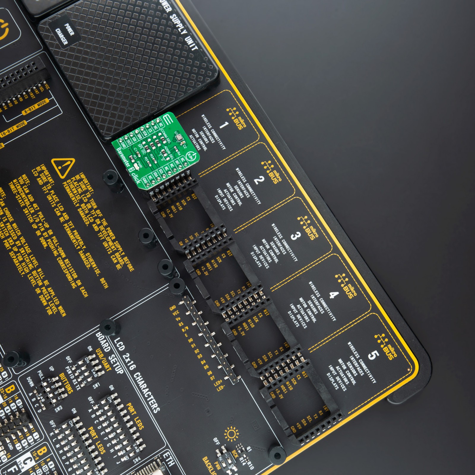
mikroBUS™
Click board size
S (28.6 x 25.4 mm)
Input Voltage
3.3V
Pinout diagram
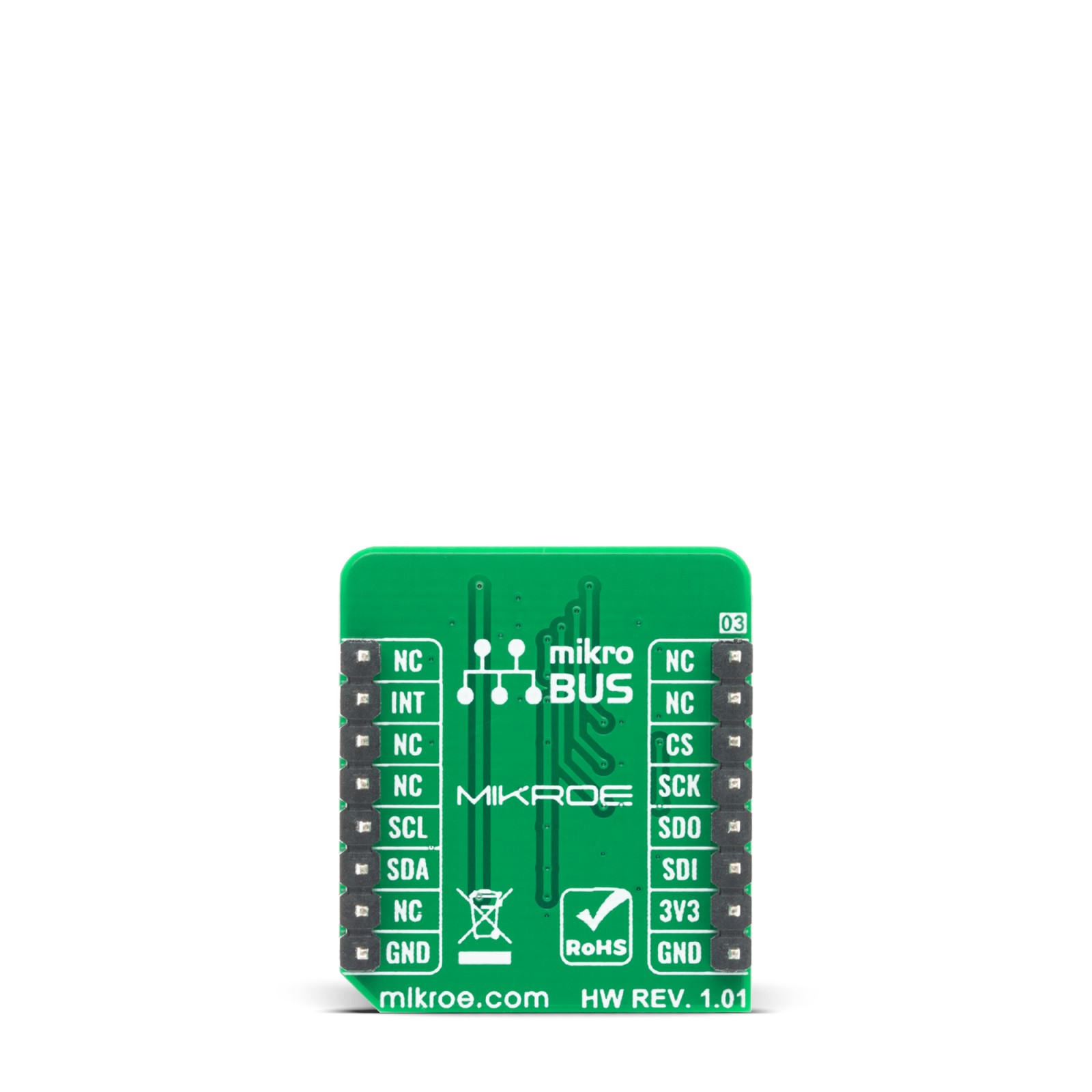
This table shows how the pinout on Barometer 3 Click corresponds to the pinout on the mikroBUS™ socket (the latter shown in the two middle columns).
Onboard settings and indicators
Label | Name | Default | Description |
---|---|---|---|
LD1 | PWR | – | Power LED Indicator |
JP1-JP4 | COMM SEL | Right | Communication selection between SPI or I2C, left position SPI, right position I2C. |
JP5 | ADDR SEL | Left | Communication interface selection: left position 1, right position 0 |
Barometer 3 Click electrical specifications
Description | Min | Typ | Max | Unit |
---|---|---|---|---|
Supply Voltage | – | 3.3 | – | V |
Pressure | 300 | – | 1200 | hPa |
Relative Accurecy | – | ±0.06 | – | hPa |
Absolute Accurecy | – | ±1 | – | hPa |
Software Support
We provide a library for the Barometer 3 Click on our LibStock page, as well as a demo application (example), developed using MikroElektronika compilers. The demo can run on all the main MikroElektronika development boards.
Library Description
The library covers all the necessary functions to control Barometer 3 click board. Library performs a standard SPI or I2C interface communication.
Key functions:
void barometer3_def_cfg ( void )
– Apply Default Configuration function.uint8_t barometer3_meas_temp_once ( float *result, uint8_t temp_osr )
– Get Temperature Measurement Once function.uint8_t barometer3_meas_prs_once ( float *result, uint8_t prs_osr )
– Get Pressure Measurement Once function.
Examples description
The application is composed of three sections :
- System Initialization – Initilization I2C module and sets INT pin as INPUT.
- Application Initialization – Initializes driver init and configuration module for measurement.
- Application Task – (code snippet) Reads Pressure data in Pascal [ Pa ]. Results are being sent to the Usart Terminal where you can track their changes. All data logs write on USB uart changes for every 1 sec.
void application_task( ) { status_val = barometer3_meas_prs_once( &pressure, BAROMETER3_PM_PRC_128 ); if ( status_val == BAROMETER3_SUCCESS ) { mikrobus_logWrite( " Pressure: ", _LOG_TEXT ); FloatToStr( pressure, log_txt ); mikrobus_logWrite( log_txt, _LOG_TEXT ); mikrobus_logWrite( " Pa", _LOG_LINE ); mikrobus_logWrite( "-----------------------", _LOG_LINE ); Delay_ms( 1000 ); } }
The full application code, and ready to use projects can be found on our LibStock page.
Other mikroE Libraries used in the example:
- SPI or I2C
- UART
- Conversions
Additional notes and informations
Depending on the development board you are using, you may need USB UART click, USB UART 2 click or RS232 click to connect to your PC, for development systems with no UART to USB interface available on the board. The terminal available in all MikroElektronika compilers, or any other terminal application of your choice, can be used to read the message.
mikroSDK
This Click board™ is supported with mikroSDK – MikroElektronika Software Development Kit. To ensure proper operation of mikroSDK compliant Click board™ demo applications, mikroSDK should be downloaded from the LibStock and installed for the compiler you are using.
For more information about mikroSDK, visit the official page.