How does it work?
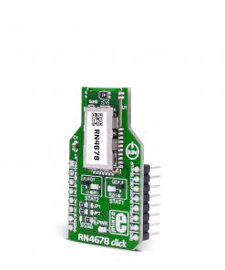
RN4678 Click is based on the RN4678, a Bluetooth 4.2 dual-mode module from Microchip. It is built around Microchip’s IS1678 Bluetooth dual-mode chip. The module includes an onboard Bluetooth stack, power management subsystem, 2.4 GHz transceiver, and RF power amplifier. It uses a transparent UART mode for seamless serial data over Bluetooth Classic using Serial Port Profile (SPP) and Bluetooth Low Energy (BLE) using Generic Attribute (GATT) Profile. In addition, the module supports also GAP, ATT, SMP, and L2CAP profiles (backward compatibility with Bluetooth 3.2). As for security, RN4678 supports AES128 encryption and Bluetooth 4.2 LE secure connection.
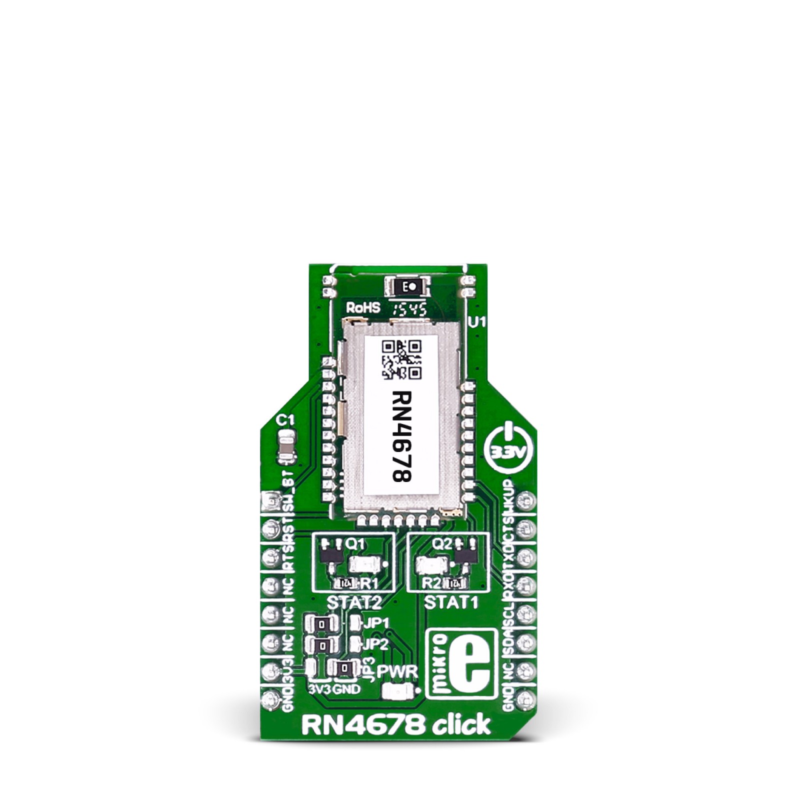
The firmware on RN4678 can be upgraded in the field over UART, and besides the library we provide, you can use an ASCII set of commands to program the module. Two status LEDs, STAT1 and STAT2, indicate one of four module statuses. For instance, STAT2 will light when the module is connected. The RN4678, as a power LED indicator, uses a dedicated LED driver integrated into the module to indicate one of five statuses over the configurable flashing sequence.
There are three jumpers labeled JP1, JP2, and JP3. By combining those jumpers, you can set the module’s operational mode. You can choose between Write Flash mode, Write EEPROM and test mode, and a Normal operation/application mode. The module comes with Normal operation/application mode, which is set by default.
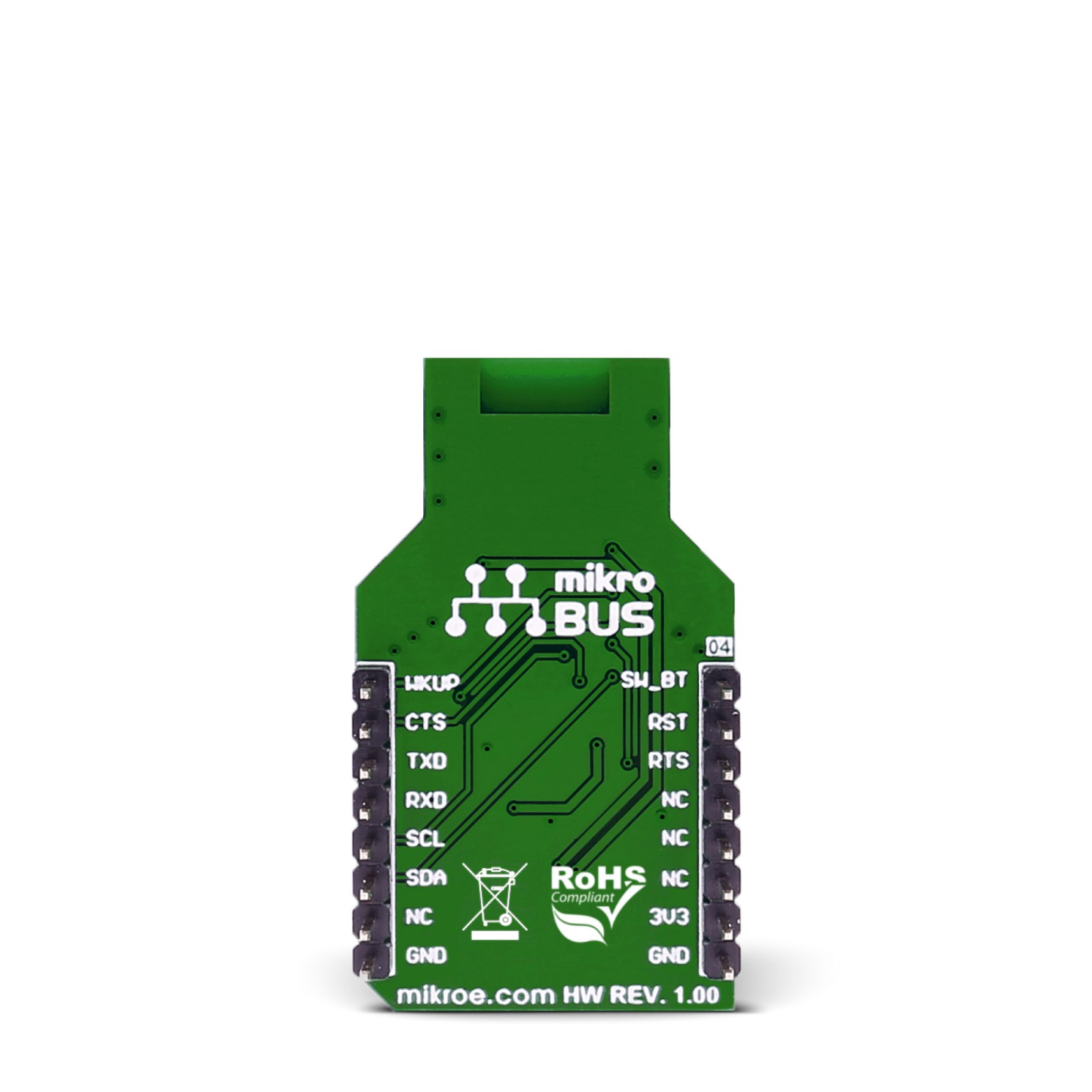
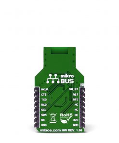
RN4678 uses a standard 2-Wire UART interface to communicate with the host MCU, supporting UART RTS and CTS control flow pins. Besides the UART interface, you can use a standard 2-Wire I2C interface to communicate with the host MCU, but without our support library. In addition, there is an RST pin for resetting the device, a WKUP pin to wake up from sleep mode, and a SW_BTPIN as a software button that acts as a power switch. After turning the module On over this pin, you must wait for a specific time before sending the first command.
This Click board™ can be operated only with a 3.3V logic voltage level. The board must perform appropriate logic voltage level conversion before using MCUs with different logic levels. However, the Click board™ comes equipped with a library containing functions and an example code that can be used as a reference for further development.
Specifications
Type
BT/BLE
Applications
Can be used for the development of IoT applications, secure payment, home and security, health and fitness, industrial and data logger, and other similar applications that require Bluetooth connectivity
On-board modules
RN4678 – Bluetooth 4.2 dual-mode module from Microchip
Key Features
Bluetooth 4.2, BLE, secure AES128 encryption, Bluetooth 4.2 LE secure connections, data packet length extension, transparent UART mode, dedicated LED driver, onboard Bluetooth stack, power management system, 2.4GHz transceiver, and RF power amplifier, onboard Bluetooth chip antenna, and more
Interface
I2C,UART
Feature
No ClickID
Compatibility
mikroBUS™
Click board size
M (42.9 x 25.4 mm)
Input Voltage
3.3V
Pinout diagram
This table shows how the pinout on RN4678 Click corresponds to the pinout on the mikroBUS™ socket (the latter shown in the two middle columns).
Onboard settings and indicators
Label | Name | Default | Description |
---|---|---|---|
LD1 | STAT2 | – | Status 2 LED Indicator |
LD2 | PWR | – | Power LED Indicator |
LD3 | STAT1 | – | Status 1 LED Indicator |
JP1 | JP1 | Left | System configuration – Along with JP2 and JP3 pins, used to set the module in any of the following three modes: Application mode (for normal operation), Test mode (to change EEPROM values), and Write Flash mode (to enter the new firmware into the module); |
JP2 | JP2 | Left | System configuration – Along with JP1 and JP3 pins, used to set the module in any of the following three modes: Application mode (for normal operation), Test mode (to change EEPROM values), and Write Flash mode (to enter the new firmware into the module); |
JP3 | JP3 | Left | System configuration – Along with JP1 and JP2 pins, used to set the module in any of the following three modes: Application mode (for normal operation), Test mode (to change EEPROM values), and Write Flash mode (to enter the new firmware into the module); |
RN4678 Click electrical specifications
Description | Min | Typ | Max | Unit |
---|---|---|---|---|
Supply Voltage | – | 3.3 | – | V |
Operating Frequency | 2402 | – | 2480 | MHz |
Data Throughput | – | – | 32 | Kbps |
Software Support
We provide a library for the RN4678 Click as well as a demo application (example), developed using MIKROE compilers. The demo can run on all the main MIKROE development boards.
Package can be downloaded/installed directly from NECTO Studio Package Manager(recommended), downloaded from our LibStock™ or found on Mikroe github account.
Library Description
This library contains API for RN4678 Click driver.
Key functions
-
Enter the command mode function
-
Exit the command mode function
-
Set the device name function
Example Description
This example reads and processes data from RN4678 clicks.
void application_task ( void )
{
rn4678_process( PROCESS_LOG_RSP );
}
The full application code, and ready to use projects can be installed directly from NECTO Studio Package Manager(recommended), downloaded from our LibStock™ or found on Mikroe github account.
Other Mikroe Libraries used in the example:
- MikroSDK.Board
- MikroSDK.Log
- Click.Rn4678
Additional notes and informations
Depending on the development board you are using, you may need USB UART click, USB UART 2 Click or RS232 Click to connect to your PC, for development systems with no UART to USB interface available on the board. UART terminal is available in all MIKROE compilers.
mikroSDK
This Click board™ is supported with mikroSDK – MIKROE Software Development Kit. To ensure proper operation of mikroSDK compliant Click board™ demo applications, mikroSDK should be downloaded from the LibStock and installed for the compiler you are using.
For more information about mikroSDK, visit the official page.