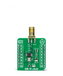
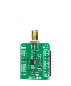
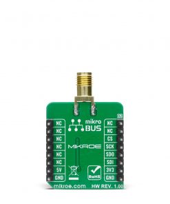

ISM TX Click
R255.00 ex. VAT
ISM TX Click is a compact add-on board that contains an ASK and (G)FSK transmitter with a programmable SPI interface. This board features the MAX41460, a UHF sub-GHz ISM/SRD transmitter designed to transmit On-Off Keying (OOK), Amplitude- Shift Keying (ASK), Frequency-Shift Keying (FSK), and Gaussian (G)FSK (or 2GFSK) data from Analog Devices. The fast response time of the integrated PLL allows for frequency-hopping, spread-spectrum protocols for increased range, and security. Its crystal-based architecture provides greater modulation depth, faster frequency settling, higher tolerance of the transmit frequency, and reduced temperature dependence. This Click board™ is fitting for remote low-speed communication, such as the remote keyless access, garage or gate doors control, home automation, and similar applications where this kind of communication is applicable.
ISM TX Click is supported by a mikroSDK compliant library, which includes functions that simplify software development. This Click board™ comes as a fully tested product, ready to be used on a system equipped with the mikroBUS™ socket.
Stock: Lead-time applicable.
| 5+ | R242.25 |
| 10+ | R229.50 |
| 15+ | R216.75 |
| 20+ | R208.59 |
How does it work?
ISM TX Click is based on the MAX41460, a UHF sub-GHz ISM/SRD transmitter designed to transmit On-Off Keying (OOK), Amplitude- Shift Keying (ASK), Frequency-Shift Keying (FSK), and Gaussian (G)FSK (or 2GFSK) data from Analog Devices. The crystal-based architecture of the MAX41460 provides greater modulation depth, faster frequency settling, higher tolerance of the transmit frequency, and reduced temperature dependence. It integrates a fractional phase-locked loop (PLL); so a single, low-cost crystal of 16MHz used on this Click board™ can generate commonly used world-wide sub-GHz frequencies. A buffered clock-out signal makes the device compatible with almost any MCU or code-hopping generator. The MAX41460 feature fast oscillator Wake-Up upon data activity detection and has an Auto-Shutdown feature to extend battery life.

This Click board™ has four major operating states: Shutdown, Stand-By, Programming, and Transmitter-Enabled Mode. These states describe the Power-ON/Power-OFF status of the transmitter’s three primary internal circuit blocks: the crystal oscillator (XO), the PLL synthesizer, and a high-efficiency, open-drain switching-mode power amplifier (PA). To ensure the MAX41460 enters the shutdown state after Power-On, the DATA pin must be held low at Power-On. The PA pin is used to adjust the frequency with only frequency-dependent components required for the external antenna-matching network that are connected in such a way that the frequency of this Click board™ is fixed to 433.92MHz.
The MAX41460 communicates with MCU using the standard SPI serial interface with a maximum frequency of 20 MHz. The device can support two types of SPI transactions: register access only, and register access followed by data transmission. In both Shutdown and Stand-By states, programming through the SPI interface is not allowed. Configuration register values are retained in all states unless changed by programming, or if the device is powered off. This Click board™, alongside power LED indicator, has an additional green LED indicator labeled as DATA used to visually indicate the successful transmission of data across the SPI interface.
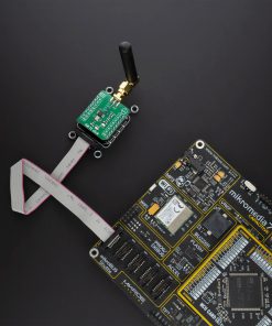
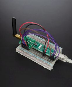
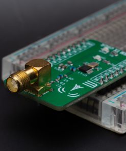
ISM TX Click possesses on itself the SMA antenna connector and it can be used for connecting the appropriate antenna that MIKROE has in its offer such as Rubber 433MHz Antenna. This antenna is an excellent choice for all GSM/GPRS applications and supports a various range of frequencies and bands.
This Click board™ is designed to be operated only with a 3.3V logic voltage level. A proper logic voltage level conversion should be performed before the Click board™ is used with MCUs with different logic levels. However, the Click board™ comes equipped with a library that contains easy to use functions and an example code that can be used as a reference for further development.
Specifications
Type
Sub-1 GHz Transceievers
Applications
Ideal for remote low-speed communication, such as the remote keyless access, garage or gate doors control, home automation, and similar applications
On-board modules
MAX41460 – UHF sub-GHz ISM/SRD transmitter from Analog Devices
Key Features
Increased range, data rates, and security, extend battery life with low supply current, selectable modes, greater modulation depth, faster frequency settling, higher tolerance of the transmit frequency, and more
Interface
SPI
Feature
No ClickID
Compatibility
mikroBUS™
Click board size
S (28.6 x 25.4 mm)
Input Voltage
3.3V
Pinout diagram
This table shows how the pinout on ISM TX Click corresponds to the pinout on the mikroBUS™ socket (the latter shown in the two middle columns).
| Notes | Pin | Pin | Notes | ||||
|---|---|---|---|---|---|---|---|
| NC | 1 | AN | PWM | 16 | NC | ||
| NC | 2 | RST | INT | 15 | NC | ||
| SPI Chip Select | CS | 3 | CS | RX | 14 | NC | |
| SPI Clock | SCK | 4 | SCK | TX | 13 | NC | |
| SPI Data OUT | SDO | 5 | MISO | SCL | 12 | NC | |
| SPI Data IN | SDI | 6 | MOSI | SDA | 11 | NC | |
| Power Supply | 3.3V | 7 | 3.3V | 5V | 10 | NC | |
| Ground | GND | 8 | GND | GND | 9 | GND | Ground |
Onboard settings and indicators
| Label | Name | Default | Description |
|---|---|---|---|
| LD1 | PWR | – | Power LED Indicator |
| LD2 | DATA | – | Data LED Indicator |
ISM TX Click electrical specifications
| Description | Min | Typ | Max | Unit |
|---|---|---|---|---|
| Supply Voltage | – | 3.3 | – | V |
| Frequency Range | – | 433.92 | – | MHz |
| ASK Modulation Depth | – | 70 | – | dB |
| Output Power | 13 | – | 16 | dBm |
Software Support
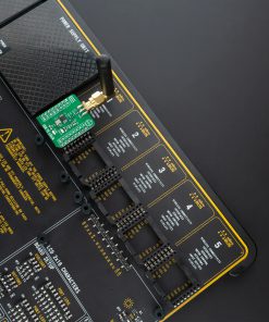
ISM TX Click demo application is developed using the NECTO Studio, ensuring compatibility with mikroSDK‘s open-source libraries and tools. Designed for plug-and-play implementation and testing, the demo is fully compatible with all development, starter, and mikromedia boards featuring a mikroBUS™ socket.
Example Description
This application shows capability of ISM TX Click board. It sets default configuration, and transmits data in manchester encoding with FSK or ASK signal modulation.
Key Functions
ismtx_cfg_setupConfig Object Initialization function.ismtx_initInitialization function.ismtx_default_cfgClick Default Configuration function.ismtx_set_cfgISM TX writing configuration.ismtx_set_frequencySetting specific frequency for transmission.ismtx_transmit_dataFunction for transmitting data with preamble byte and lenght.
Application Init
Initialization of log and communication, set’s signal modulation, resets device, and set’s default configuration for selected modulation.
Application Task
Transmits data via external antenna in span of 100ms.
Application Output
This Click board can be interfaced and monitored in two ways:
- Application Output – Use the “Application Output” window in Debug mode for real-time data monitoring. Set it up properly by following this tutorial.
- UART Terminal – Monitor data via the UART Terminal using a USB to UART converter. For detailed instructions, check out this tutorial.
Additional Notes and Information
The complete application code and a ready-to-use project are available through the NECTO Studio Package Manager for direct installation in the NECTO Studio. The application code can also be found on the MIKROE GitHub account.
Resources
Downloads
| Weight | 19 g |
|---|---|
| Brand | MikroElektronika |