How does it work?
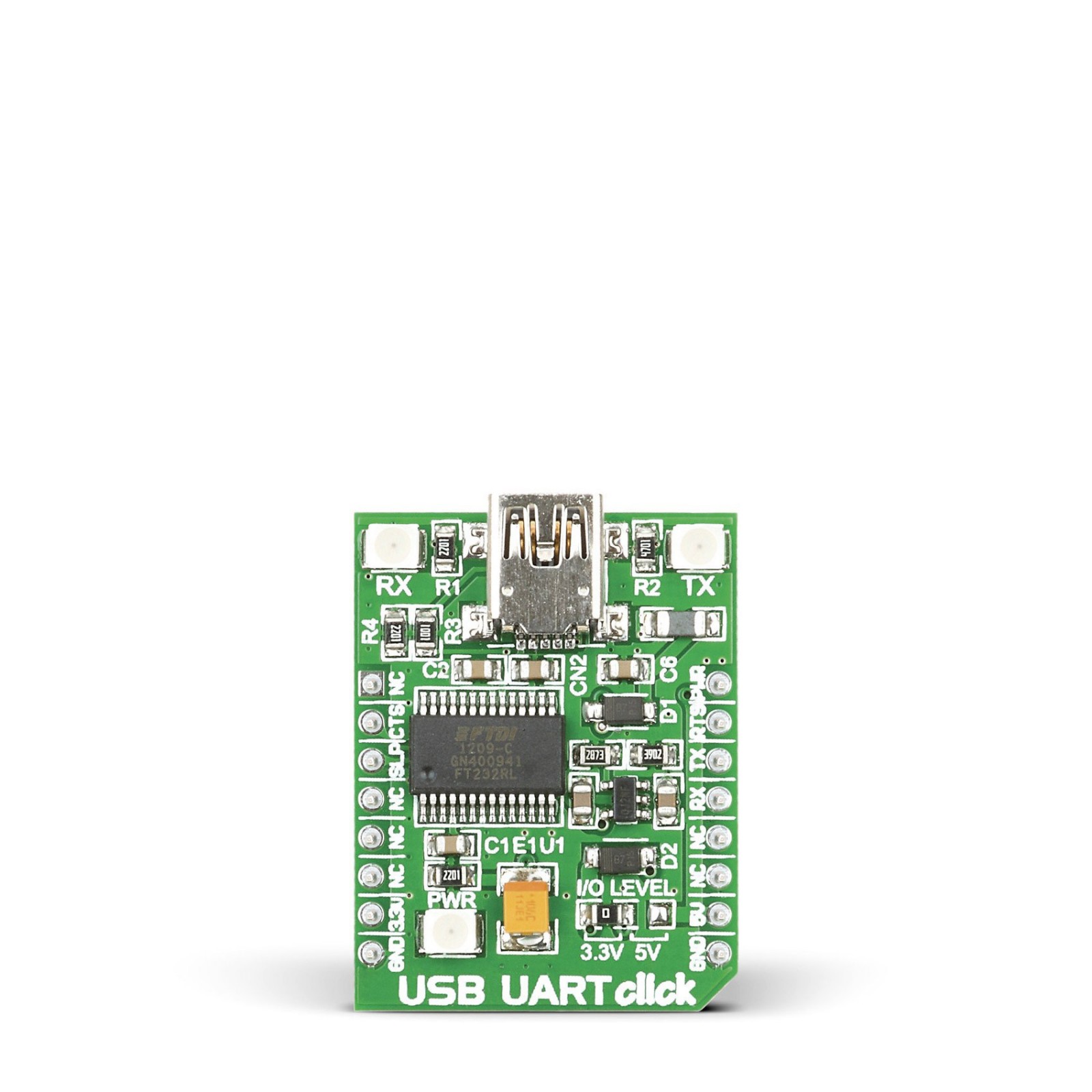
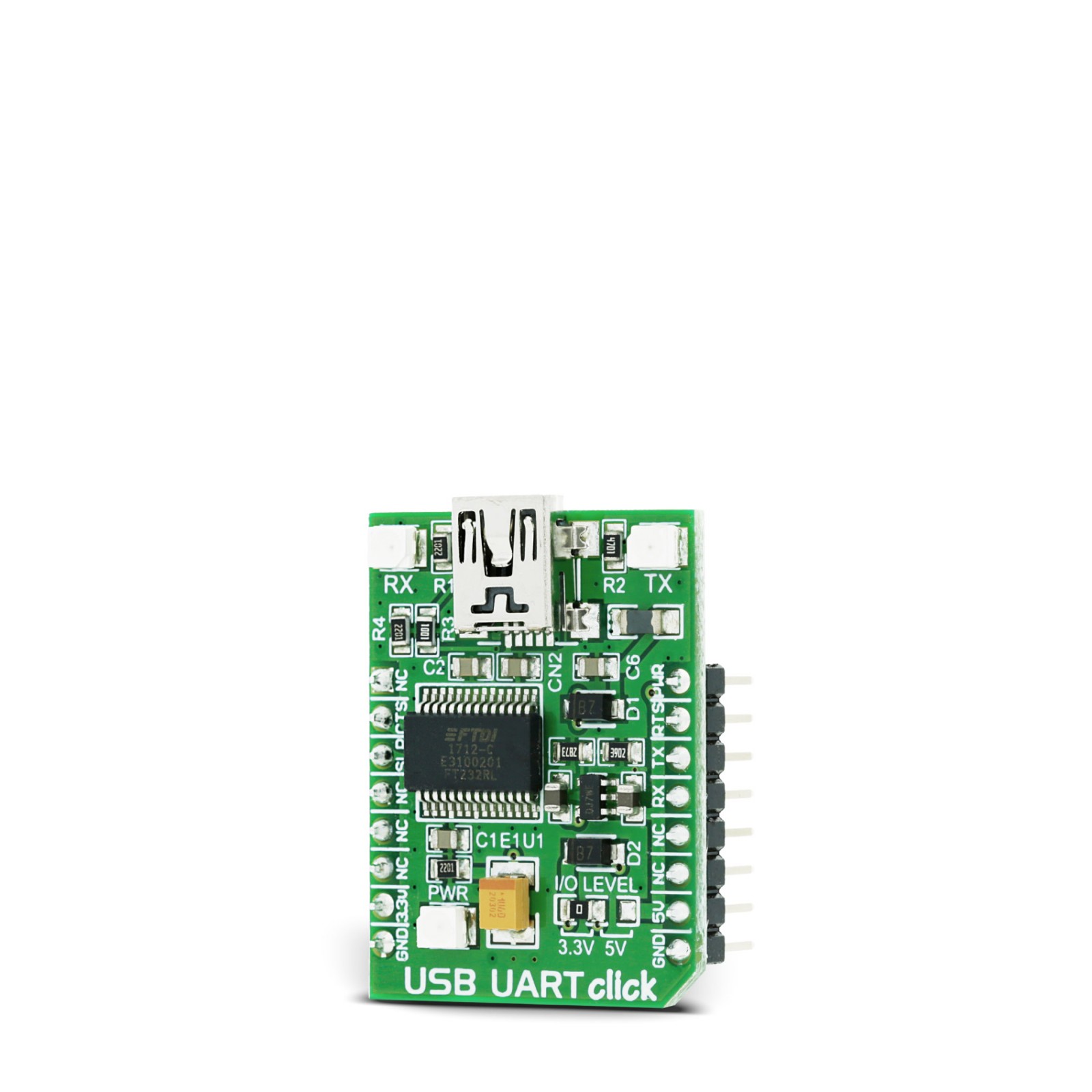
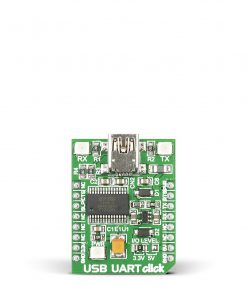
USB UART Click is based on the FT232RL, a USB to serial UART bridge from FTDI Chip. The entire USB protocol is handled on the IC; thus, no USB-specific firmware programming is required. FTDI provides royalty-free Virtual Com Port (VCP) and Direct (D2XX) drivers for all the major OSes used on personal computers. FT232RL also contains an integrated 1024-bit internal EEPROM for storing USB VID, PID, serial number, product description strings, and CBUS I/O configuration. After installing the OS drivers, the device is ready to be used. When plugged into the PC over the mini-USB connector, it will create a virtual COM port.
The Baud Rate Generator provides a 16x clock input to the UART Controller from the 48MHz reference clock. This determines the baud rate of the UART, which is programmable from 183 baud to 3 Mbaud. Also, non-standard baud rates are supported. The FTDI driver automatically calculates the baud rate, so it is enough to forward the desired baud rate to the driver, usually done by selecting the baud rate via the GUI interface of the PC terminal application.
USB UART Click uses a standard 2-Wire UART interface to communicate with the host MCU, with commonly used UART RX and TX pins. In addition, you can use the UART flow control pins RTS and CTS. LEDs RX and TX are here for visual presentation of data flow.
This device also features configurable CBUS pins, which can be used for several different useful functions, for example – configurable clock out for driving the microcontroller, data LED drive, USB Sleep, PWR status, and more. By default, CBUS3 and CBUS4 pins are configured as Power Enable (PWR) and Sleep options (SLP). CBUS3 output pin will be set to a LOW logic state during the USB suspend mode. It can power down external circuitry or be used for similar purposes. CBUS4 output pin will be set to a LOW logic state after the USB has configured the device, then HIGH during the USB suspend mode. This can also be used for powering down/power saving by turning unneeded external circuitry.
This Click board™ can operate with either 3.3V or 5V logic voltage levels selected via the I/O LEVEL SEL jumper. This way, both 3.3V and 5V capable MCUs can use the communication lines properly. Also, this Click board™ comes equipped with a library containing easy-to-use functions and an example code that can be used as a reference for further development.
Specifications
Type
USB
Applications
Can be used for the development of various applications that use a UART communication protocol, PC applications, RS232 communication with modems, and more
On-board modules
FT232RL – USB to serial UART bridge from FTDI Chip
Key Features
The FT232RL contains integrated 1024-bit EEPROM, 128 bytes long receive buffer, 256 bytes long transmit buffer, the entire USB protocol handled on the chip, FTDI’s royalty-free Virtual Com Port (VCP) and Direct (D2xx) drivers, unique USB FTDIChip ID, configurable CBUS I/O pins, and more
Interface
UART,USB
Feature
No ClickID
Compatibility
mikroBUS™
Click board size
M (42.9 x 25.4 mm)
Input Voltage
3.3V or 5V
Pinout diagram
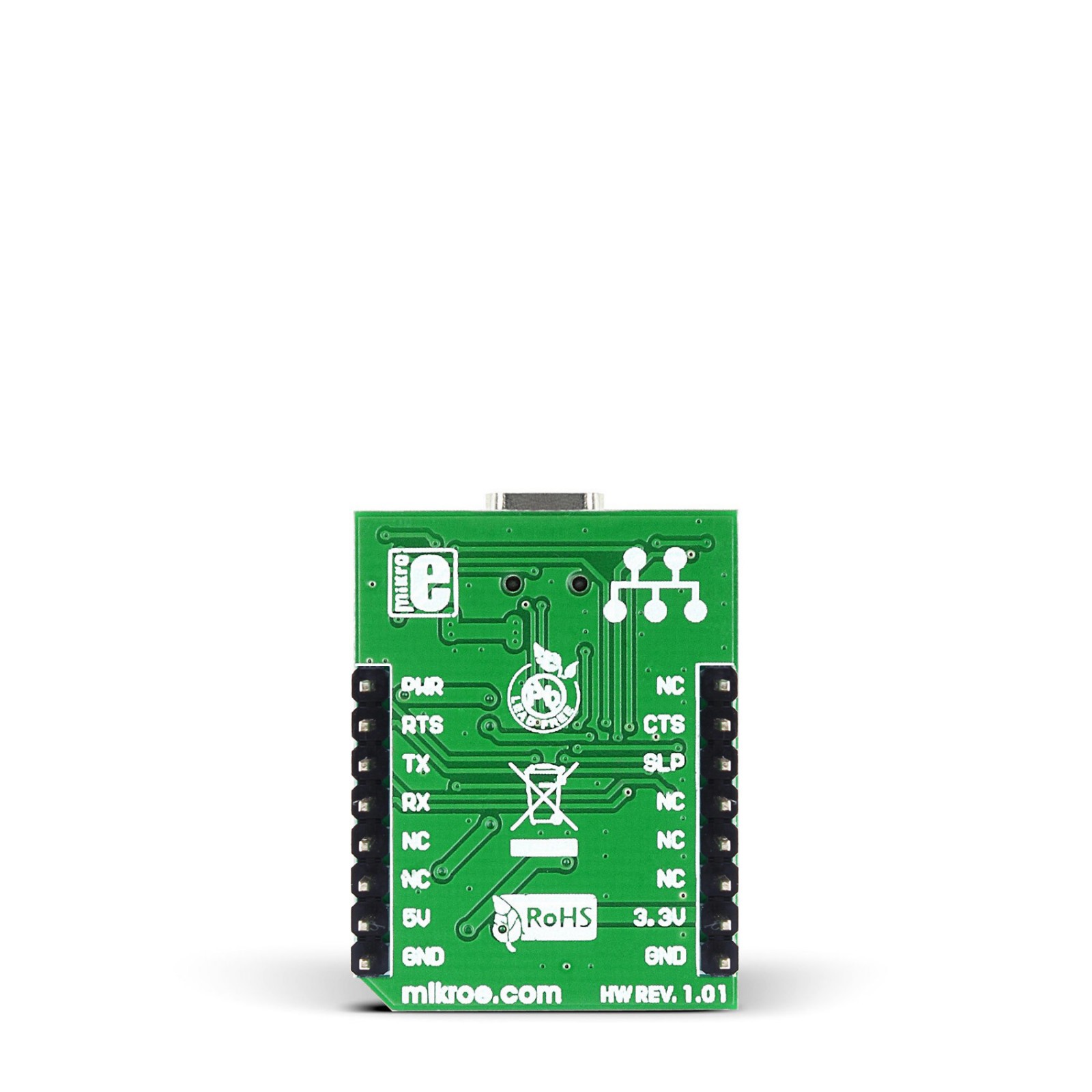
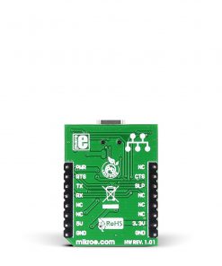
This table shows how the pinout on USB UART click corresponds to the pinout on the mikroBUS™ socket (the latter shown in the two middle columns).
Onboard settings and indicators
Label | Name | Default | Description |
---|---|---|---|
LD1C | RX | – | RX LED Indicator |
LD2B | TX | – | TX LED Indicator |
LD3A | PWR | – | Power LED Indicator |
J1A | I/O LEVEL | Left | Logic Level Voltage Selection 3V3/5V: Left position 3V3, Right position 5V |
USB UART click electrical specifications
Description | Min | Typ | Max | Unit |
---|---|---|---|---|
Supply Voltage | 3.3 | – | 5 | V |
Baud Rate | 0.0183 | – | 3 | Mbps |
Reference Clock Signal | 6 | – | 48 | MHz |
Software Support
We provide a library for the USB UART Click as well as a demo application (example), developed using MIKROE compilers. The demo can run on all the main MIKROE development boards.
Package can be downloaded/installed directly from NECTO Studio Package Manager(recommended), downloaded from our LibStock™ or found on Mikroe github account.
Library Description
This library contains API for USB UART Click driver.
Key functions
-
usbuart_pwr_ctrl
This function sets the click turns click on. -
usbuart_set_cts
This function sets CTS pin. -
usbuart_send_command
This function is used for sending commands.
Example Description
This example reads and processes data from USB UART clicks.
void application_task ( void ) {
app_buf_len = usbuart_generic_read( &usbuart, app_buf, PROCESS_BUFFER_SIZE );
if ( app_buf_len > 0 ) {
log_printf( &logger, "%s", app_buf );
memset( app_buf, 0, PROCESS_BUFFER_SIZE );
}
}
The full application code, and ready to use projects can be installed directly from NECTO Studio Package Manager(recommended), downloaded from our LibStock™ or found on Mikroe github account.
Other Mikroe Libraries used in the example:
- MikroSDK.Board
- MikroSDK.Log
- Click.USBUART
Additional notes and informations
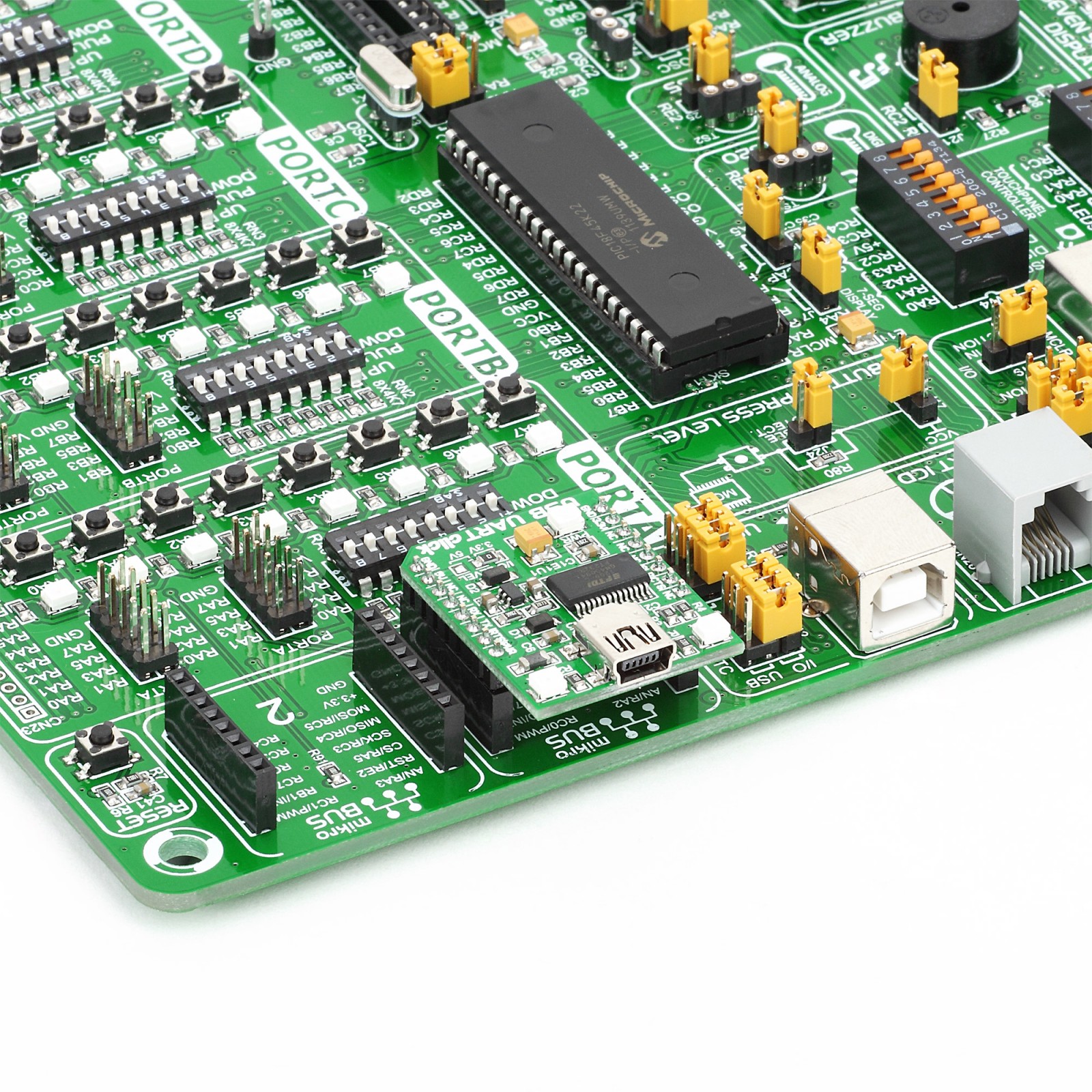
Depending on the development board you are using, you may need USB UART click, USB UART 2 Click or RS232 Click to connect to your PC, for development systems with no UART to USB interface available on the board. UART terminal is available in all MIKROE compilers.
mikroSDK
This Click board™ is supported with mikroSDK – MIKROE Software Development Kit. To ensure proper operation of mikroSDK compliant Click board™ demo applications, mikroSDK should be downloaded from the LibStock and installed for the compiler you are using.
For more information about mikroSDK, visit the official page.