How does it work?
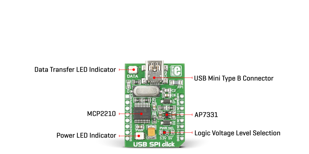
USB SPI Click is based on the MCP2210, a USB-to-SPI Master converter from Microchip. The MCP2210 has a built-in USB 2.0, a full-speed transceiver connected to the USB module, and 256 bytes of integrated user EEPROM. It is supported by most operating systems (Windows, Linux, and Mac), and enumerated only as a Human Interface Device (HID), so all the other functionalities can be controlled and configured. Besides, the MCP2210 supports signaling important USB-related events such as USB suspend and resume, successfully enumerated, and for low-power operation mode.
All modules inside the MCP2210 are tied together and controlled via the control module, which represents the heart of the MCP2210. The control module manages the data transfers between the USB and the SPI, as well as command requests generated by the USB host controller and commands for controlling the SPI and I/O function.
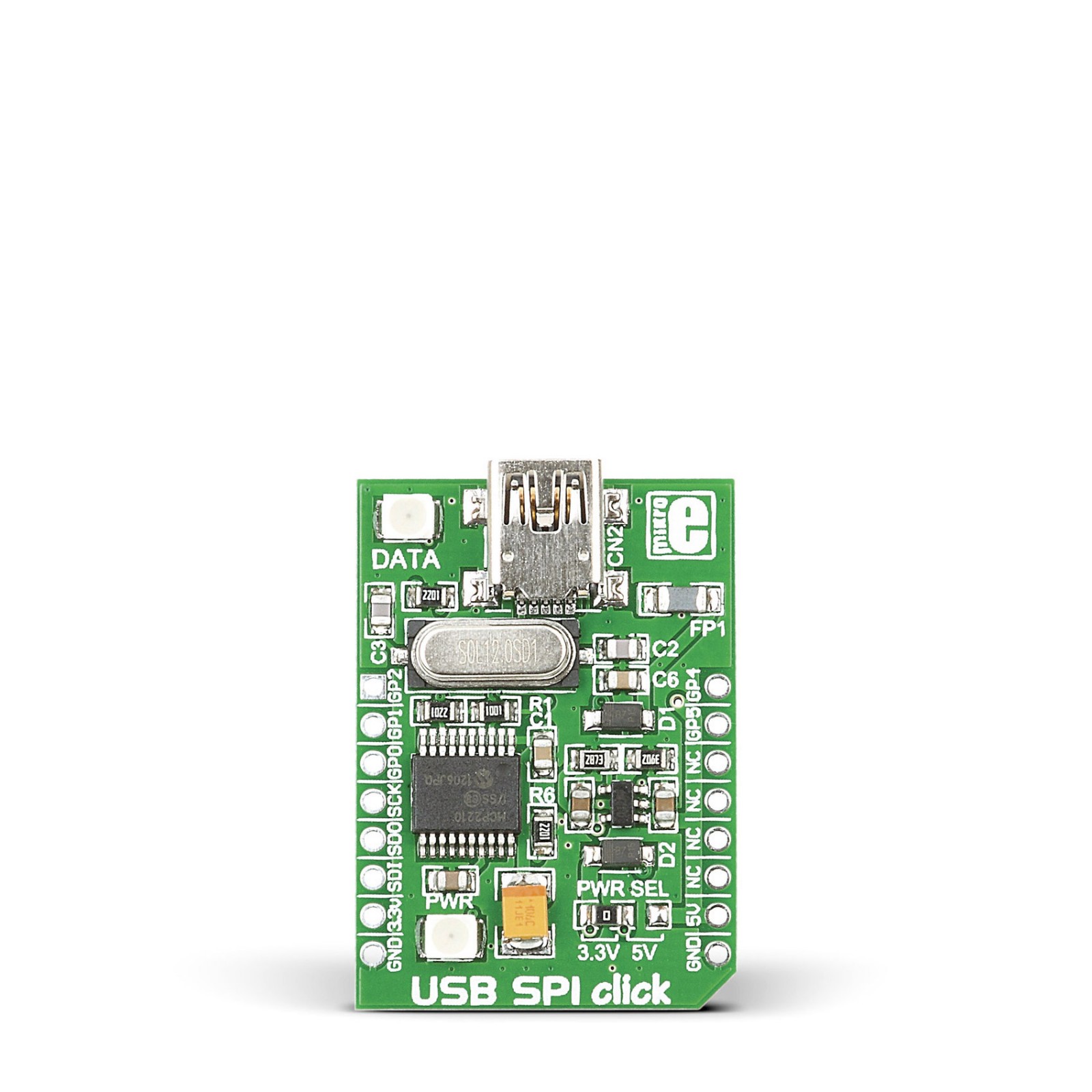
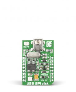
USB SPI Click communicates with the target board via the SPI interface as a Master device. The MCP2210 also has several general-purpose input/output pins routed to some of the mikroBUS™ socket pins, where some of them, besides GPIO, also alternate functions. The GP1 pin routed to the RST pins of the mikroBUS™ socket is a basic GPIO pin, the GP2 pin (AN pin of mikroBUS™ socket) reflects the USB state (Suspend/Resume), the GP4 pin (PWM pin of mikroBUS™ socket) signals when the host does not accept the requirements (presented during enumeration) and the chip is not configured, and the GP5 pin (INT pin of mikroBUS™ socket) serves as interrupt and indicates USB configuration status. In addition to all these features, this board has one LED indicator, a yellow LED marked with DATA used as an SPI traffic (data transfer) indication.
This Click board™ can operate with both 3.3V and 5V logic voltage levels. Considering that the board can be powered via USB and used as a standalone device, using an additional LDO, the AP7331, in this way, the existence of the voltage of both mikroBUS™ power lines is ensured, allowing for both 3.3V and 5V capable MCUs to use the communication lines properly. However, the Click board™ comes equipped with a library containing easy-to-use functions and an example code that can be used as a reference for further development.
Specifications
Type
USB
Applications
Can be used for SPI-based designs for serial data transfer and analysis and many other USB functions
On-board modules
MCP2210 – USB-to-SPI Master converter from Microchip
Key Features
Low power consumption, supports Full-Speed USB (12Mb/s). USB 2.0 compliant, GPIO pins with additional features, 256-bytes of user EEPROM (accessible through certain USB commands), and more
Interface
GPIO,SPI,USB
Feature
No ClickID
Compatibility
mikroBUS™
Click board size
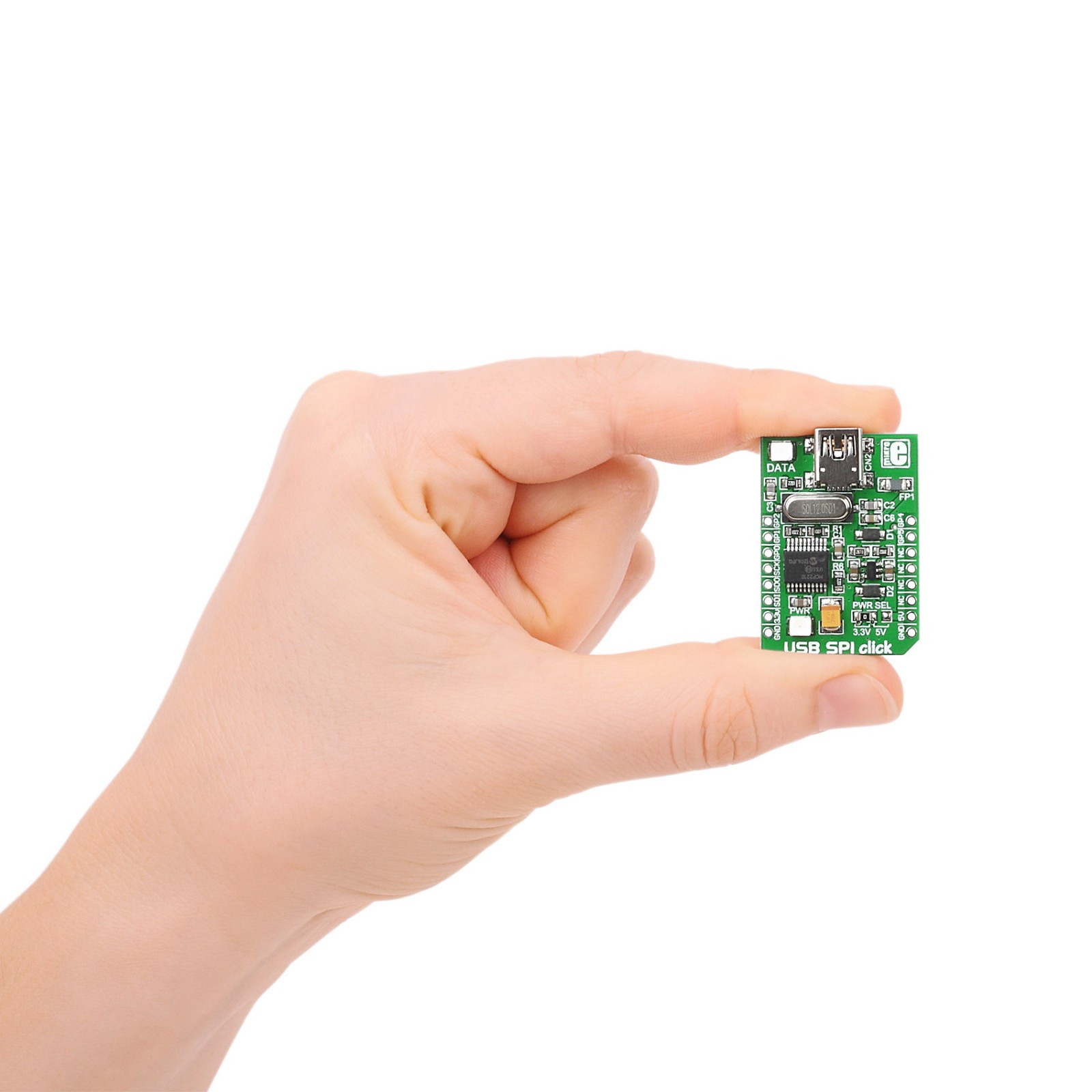
S (28.6 x 25.4 mm)
Input Voltage
3.3V or 5V
Pinout diagram
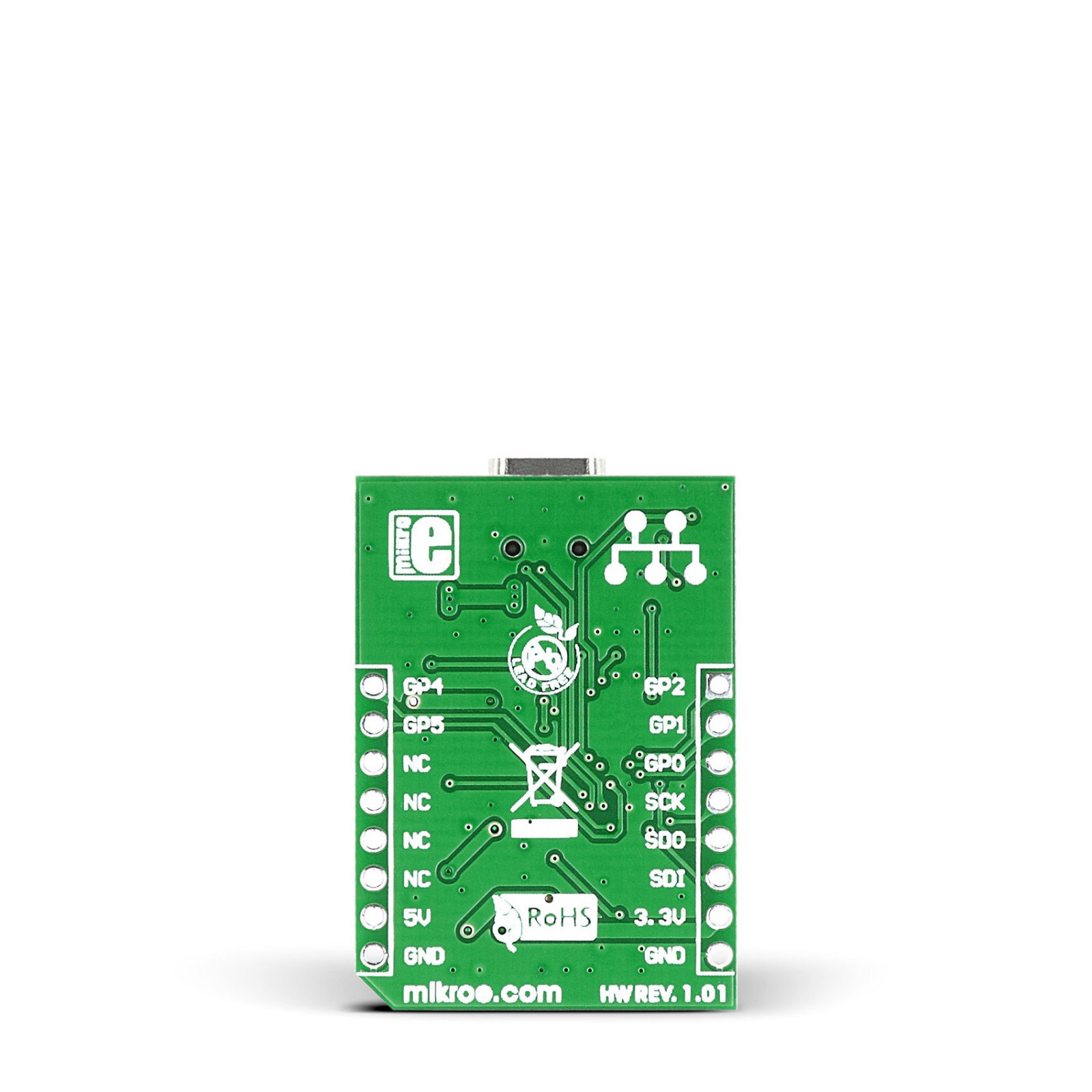
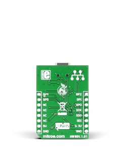
This table shows how the pinout on USB SPI Click corresponds to the pinout on the mikroBUS™ socket (the latter shown in the two middle columns).
Onboard settings and indicators
Label | Name | Default | Description |
---|---|---|---|
LD1 | PWR | – | Power LED Indicator |
LD2 | DATA | – | Data Transfer LED Indicator |
JP1 | PWR SEL | Left | Logic Level Voltage Selection 3V3/5V: Left position 3V3, Right position 5V |
USB SPI Click electrical specifications
Description | Min | Typ | Max | Unit |
---|---|---|---|---|
Supply Voltage | 3.3 | – | 5 | V |
Data Rate | – | – | 12 | Mbps |