How does it work?
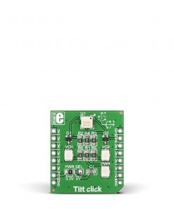
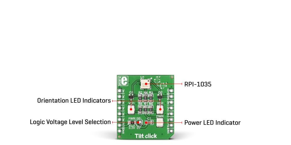
Tilt Click is based on the RPI-1035, a four-directional optical tilt sensor from Rohm Semiconductor, capable of sensing a change in orientation in four different directions: forward, back, left, or right. Compared to mechanical solutions, this optical direction detector is less prone to noise caused by vibrations. Also, the RPI-1035 is not influenced by magnetic disturbances compared to magnetic-based direction detectors. Based on various quality features, this Click board™ is ideal in cases where it is only necessary to detect movement direction, avoiding using a much more expensive accelerometer.
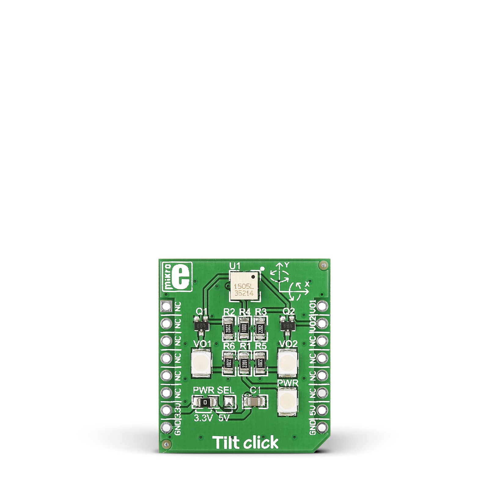
The operation of the RPI-1035 is straightforward. Inside the sensor is an infrared LED, which communicates with two photosensitive receivers through a reflective surface. Between these components and the reflective surface is a sort of cover that, depending on the movement of the component, can cover the IR sensor or the receivers. Depending on the detected direction, this sensor forwards information to the host MCU through the two mikroBUS™ lines, VO1 and VO2, routed to the PWM and INT pins of the mikroBUS™ socket. Also, in addition to digital information, this board has two red LEDs providing visual feedback from the sensor.
This Click board™ can operate with both 3.3V and 5V logic voltage levels selected via the PWR SEL jumper. This way, it is allowed for both 3.3V and 5V capable MCUs to use the communication lines properly. However, the Click board™ comes equipped with a library containing easy-to-use functions and an example code that can be used, as a reference, for further development.
Specifications
Type
Motion,Vibration
Applications
Can be used to detect the direction of movement
On-board modules
RPI-1035 – four-directional optical tilt sensor from Rohm Semiconductor
Key Features
Less prone to noise caused by vibrations, non-influenced by magnetic disturbances, Communicating with the host MCU through the two mikroBUS™ lines, two onboard LEDs for visual feedback, and more
Interface
GPIO
Feature
No ClickID
Compatibility
mikroBUS™
Click board size
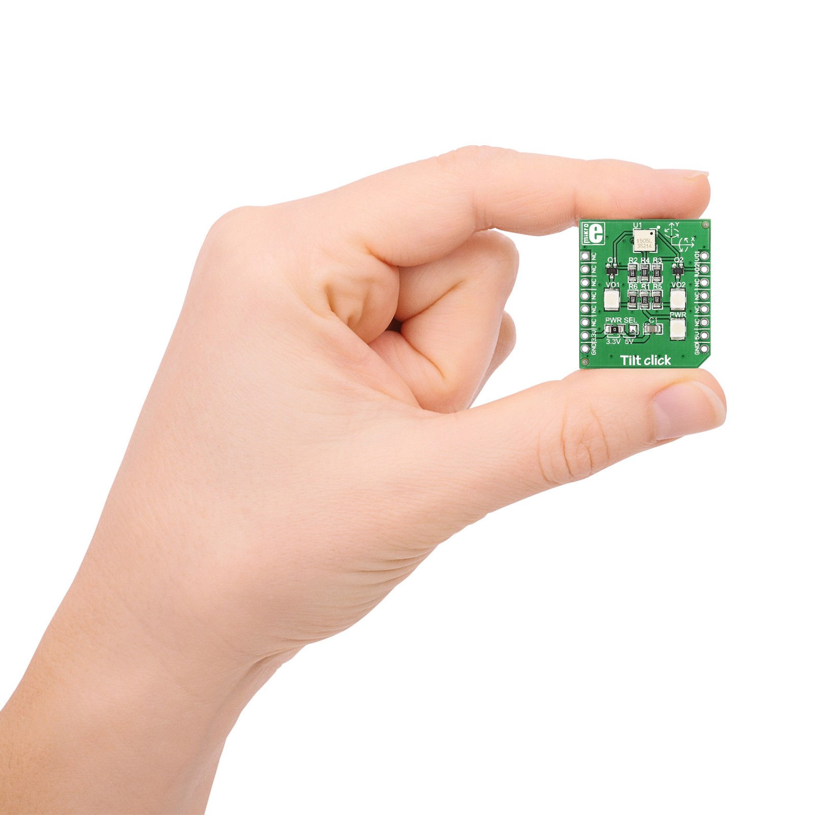
S (28.6 x 25.4 mm)
Input Voltage
3.3V or 5V
Pinout diagram
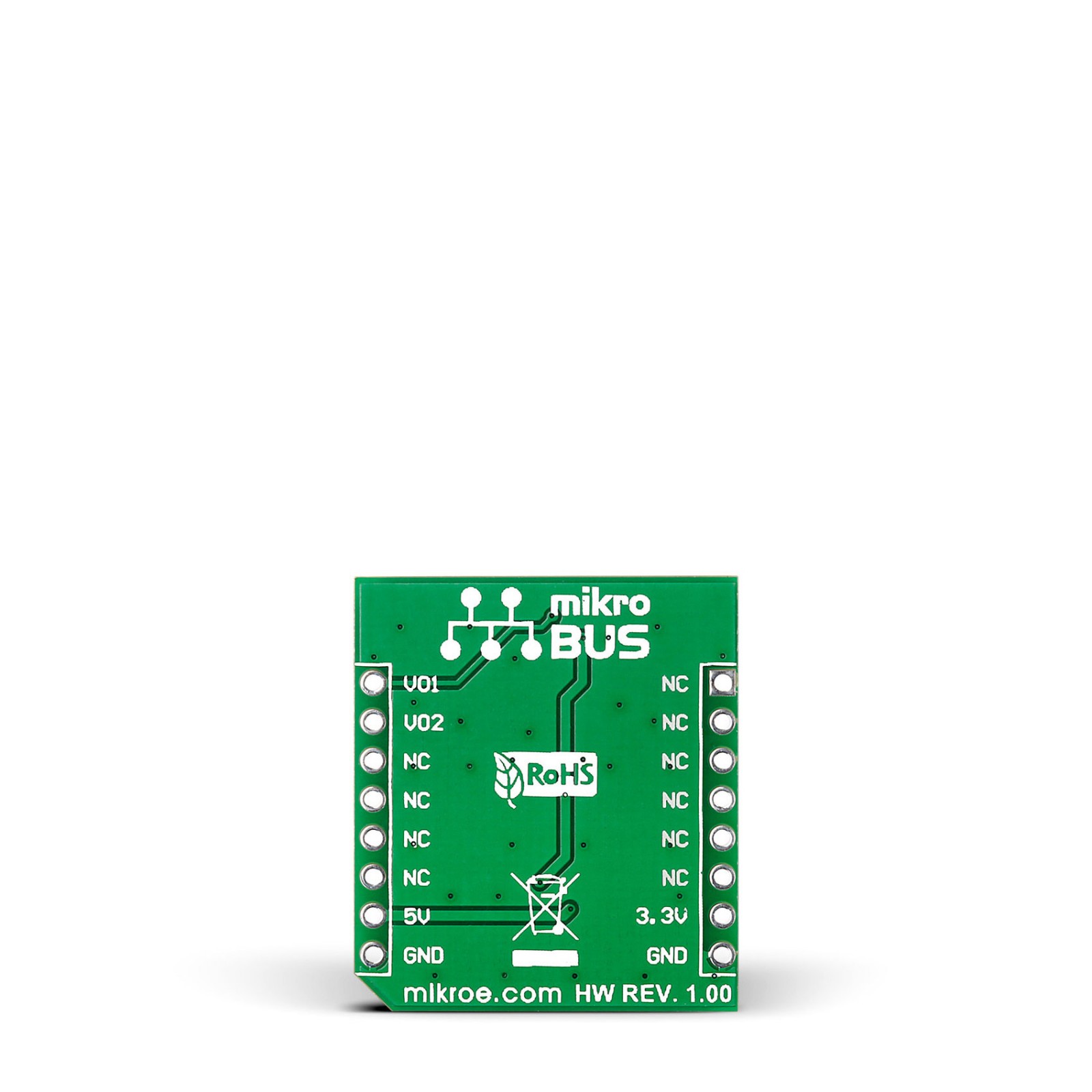
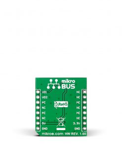
This table shows how the pinout on Tilt Click corresponds to the pinout on the mikroBUS™ socket (the latter shown in the two middle columns).
Onboard settings and indicators
Label | Name | Default | Description |
---|---|---|---|
LD1 | PWR | – | Power LED Indicator |
LD2-LD3 | VO1-VO2 | – | Orientation LED Indicators |
JP1 | PWR SEL | Left | Logic Level Voltage Selection 3V3/5V: Left position 3V3, Right position 5V |
Tilt Click electrical specifications
Description | Min | Typ | Max | Unit |
---|---|---|---|---|
Supply Voltage | 3.3 | – | 5 | V |
Operating Temperature Range | -25 | +25 | +85 | °C |
Software Support
We provide a library for the Tilt Click as well as a demo application (example), developed using MikroElektronika compilers. The demo can run on all the main MikroElektronika development boards.
Package can be downloaded/installed directly from NECTO Studio Package Manager(recommended way), downloaded from our LibStock™ or found on Mikroe github account.
Library Description
This library contains API for Tilt Click driver.
Key functions
- Check the tilt movement’s direction function.
Example Description
This is a example which demonstrates the use of Tilt Click board.
void application_task ( void )
{
tilt_direction = tilt_direction( &tilt );
if ( tilt_direction_old != tilt_direction )
{
if ( tilt_direction == TILT_LEFT_DETECTION )
{
log_printf(&logger, " LEFT rn");
}
if ( tilt_direction == TILT_RIGHT_DETECTION )
{
log_printf(&logger, " RIGHT rn");
}
if ( tilt_direction == TILT_UP_DETECTION )
{
log_printf(&logger, " UP rn");
}
if ( tilt_direction == TILT_DOWN_DETECTION )
{
log_printf(&logger, " DOWN rn");
}
tilt_direction_old = tilt_direction;
log_printf(&logger, "-------------rn");
}
}
The full application code, and ready to use projects can be installed directly from NECTO Studio Package Manager(recommended way), downloaded from our LibStock™ or found on Mikroe github account.
Other Mikroe Libraries used in the example:
- MikroSDK.Board
- MikroSDK.Log
- Click.Tilt
Additional notes and informations
Depending on the development board you are using, you may need USB UART click, USB UART 2 Click or RS232 Click to connect to your PC, for development systems with no UART to USB interface available on the board. UART terminal is available in all MikroElektronika compilers.
mikroSDK
This Click board™ is supported with mikroSDK – MikroElektronika Software Development Kit. To ensure proper operation of mikroSDK compliant Click board™ demo applications, mikroSDK should be downloaded from the LibStock and installed for the compiler you are using.
For more information about mikroSDK, visit the official page.