How does it work?
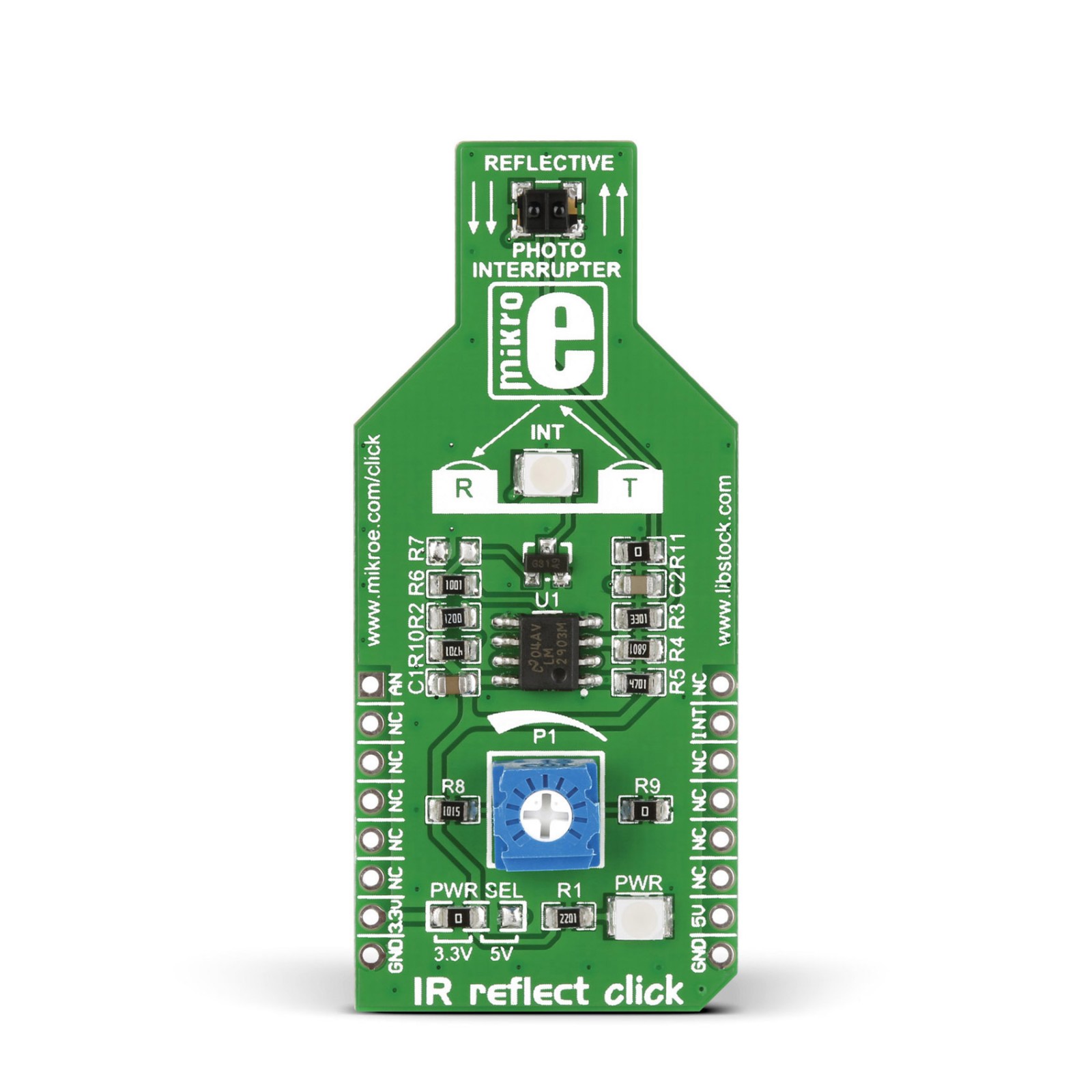
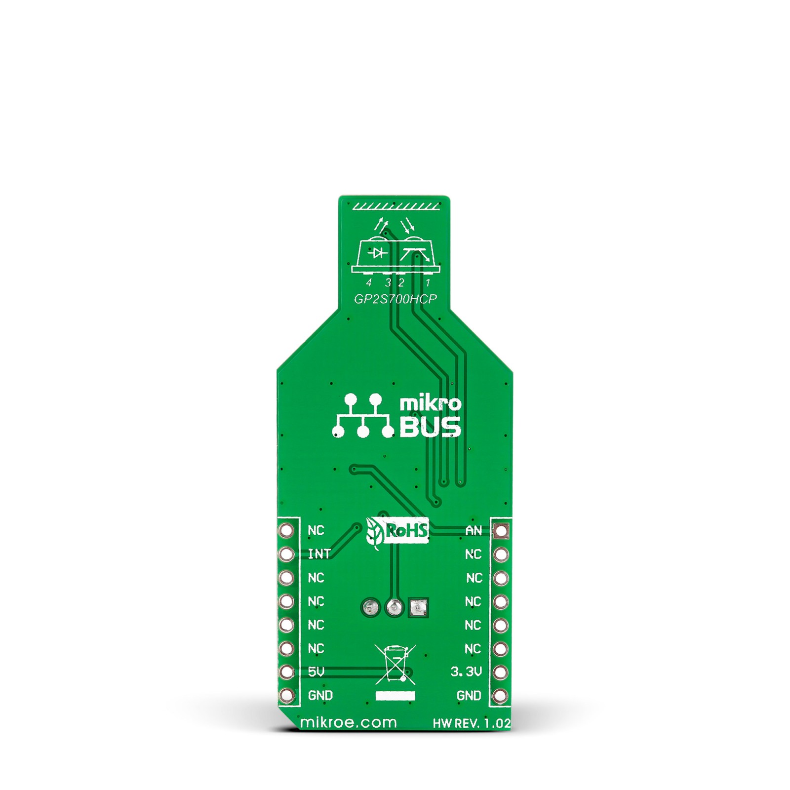
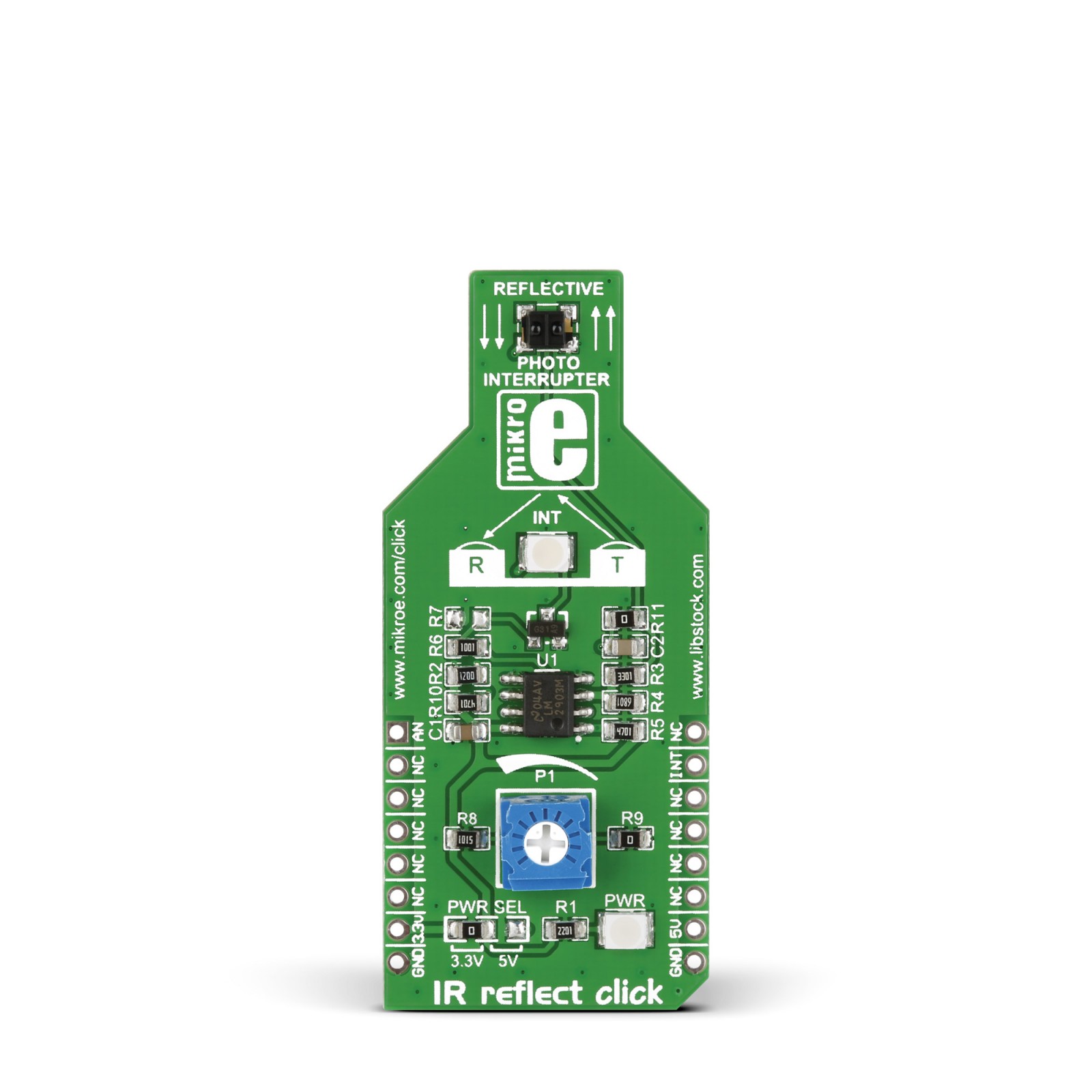
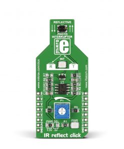
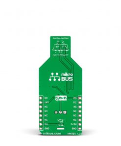
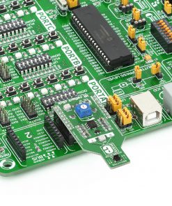
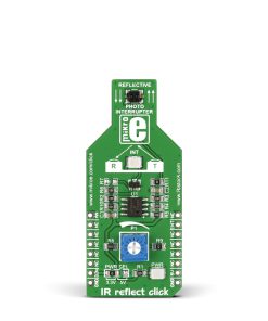
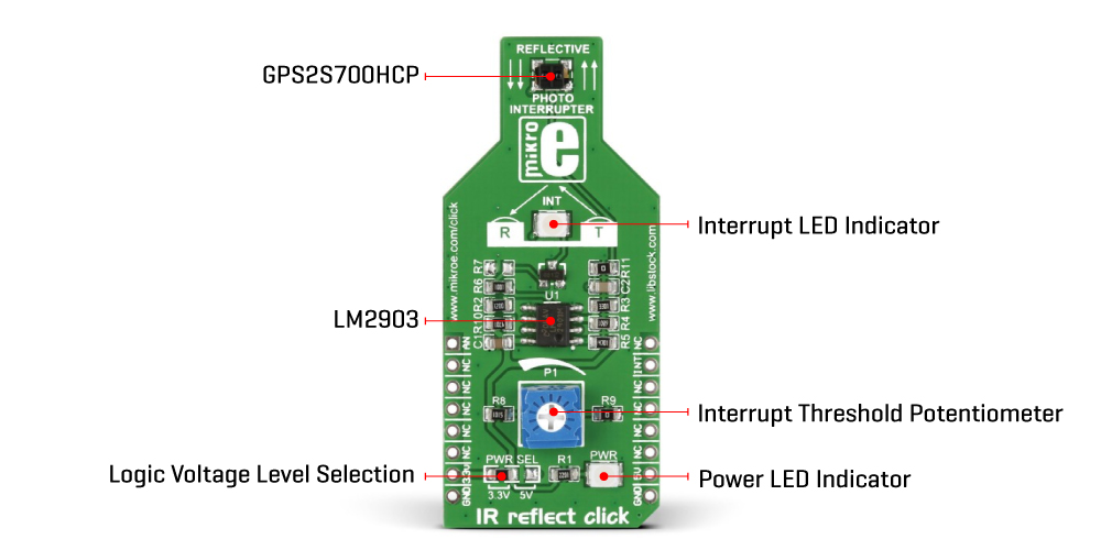
IR Reflect is based on the GP2S700HCP, a phototransistor output reflective photo interrupter from Sharp Microelectronics. It consists of one infrared emitter and one receiver facing the same direction towards the object. When the infrared beam from the emitter bounces back to the emitter when an object is placed within range, it triggers the photo interrupter, thus activating the sensor. The board can set off a false alarm if the sensor is exposed to other infrared light sources, such as an ordinary incandescent light bulb. Infrared light will not reflect from the black surface, so the Click board™ will not detect it either. Meanwhile, reflective metallic surfaces will trigger the sensor from a more extensive range.
The IR Reflect Click board communicates with the host MCU by sending analog values over the AN pin of the mikroBUS™ socket. In addition, this Click board™ features an LM2903, a low-power dual voltage comparator from STMicroelectronics. With the help of a P1 potentiometer and this voltage comparator, it is possible to set an interrupt threshold that can provide information over an INT pin of this Click board™. The interrupt will also trigger an INT LED as a visual indicator.
This Click board™ can operate with either 3.3V or 5V logic voltage levels selected via the PWR SEL jumper. This way, both 3.3V and 5V capable MCUs can use the communication lines properly. However, the Click board™ comes equipped with a library containing easy-to-use functions and an example code that can be used, as a reference, for further development.
Specifications
Type
Optical
Applications
Can be used for projects that require detection of an object’s presence or motion, such as a piece of paper passing through a printer
On-board modules
GP2S700HCP – phototransistor output and reflective photo interrupter from Sharp Microelectronics
Key Features
Photo interrupter ability for any application, up to 3mm detection space, detection through digital and analog signals, object detection LED indicator, board compatible with both 3.3V and 5V capable MCUs, and more
Interface
Analog,GPIO
Feature
No ClickID
Compatibility
mikroBUS™
Click board size
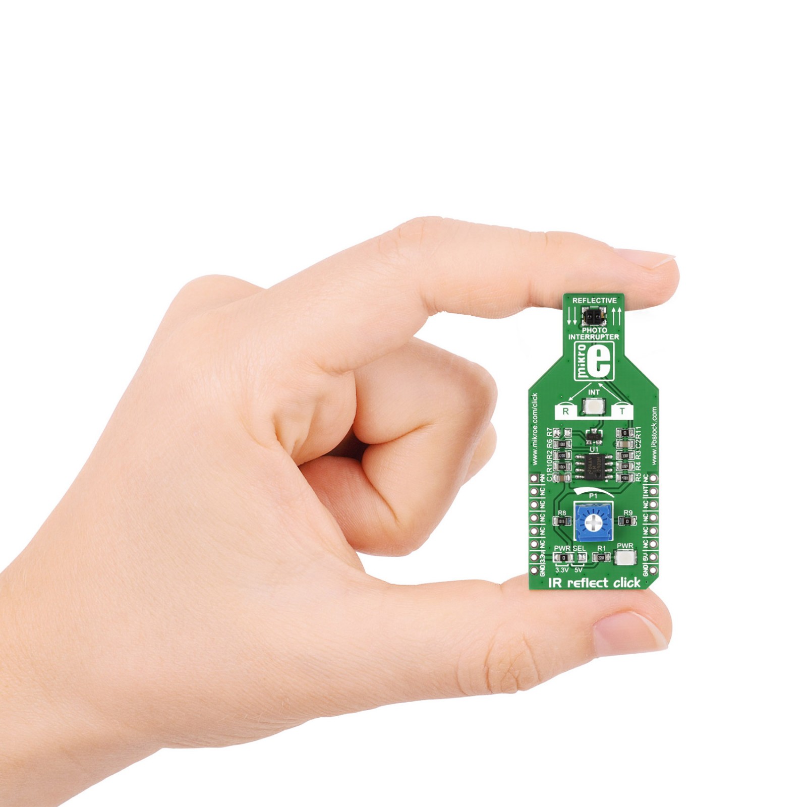
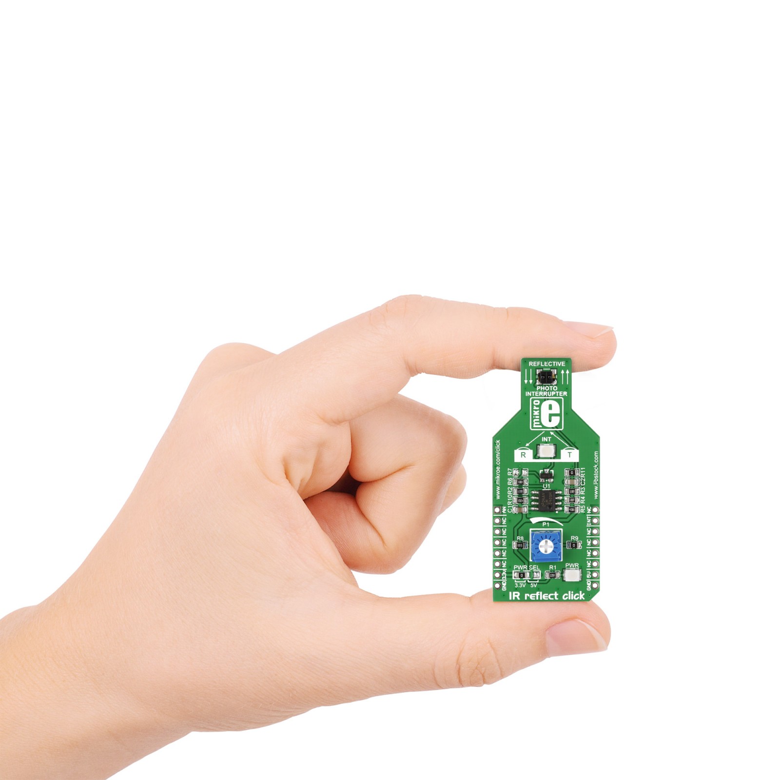
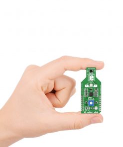
M (42.9 x 25.4 mm)
Input Voltage
3.3V or 5V
Pinout diagram
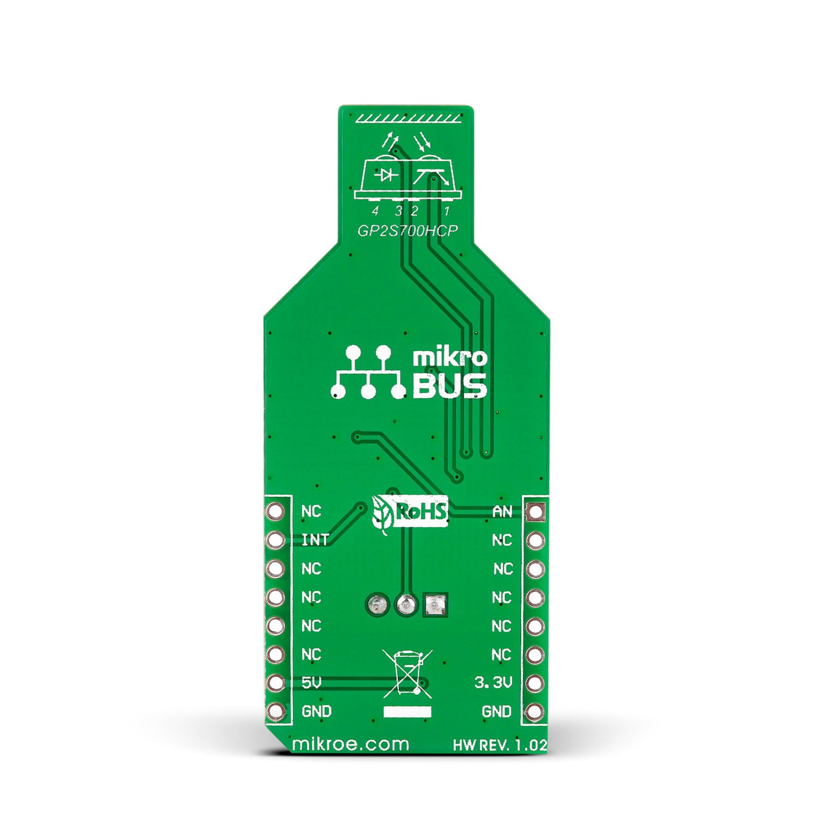
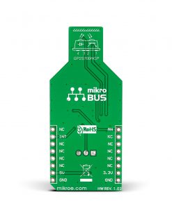
This table shows how the pinout on IR REFLECT Click corresponds to the pinout on the mikroBUS™ socket (the latter shown in the two middle columns).
Onboard settings and indicators
Label | Name | Default | Description |
---|---|---|---|
JD1 | PWR | – | Power LED Indicator |
JD2 | INT | – | Object Detection LED Indicator |
– | PWR SEL | Left | Logic Level Voltage Selection 3V3/5V: Left position 3V3, Right position 5V |
IR REFLECT Click electrical specifications
Description | Min | Typ | Max | Unit |
---|---|---|---|---|
Supply Voltage | 3.3 | – | 5 | V |
Sensing Distance | – | – | 3 | mm |
Software Support
We provide a library for the IRNSS Click as well as a demo application (example), developed using Mikroe compilers. The demo can run on all the main Mikroe development boards.
Package can be downloaded/installed directly from NECTO Studio Package Manager (recommended), downloaded from our LibStock™ or found on Mikroe github account.
Library Description
This library contains API for IRNSS Click driver.
Key functions
-
irnss_set_rst_pin_state
This function sets rst pin output to state setting. -
irnss_generic_read
This function reads a desired number of data bytes by using UART serial interface. -
irnss_parse_gngga
This function parses the GNGGA data from the read response buffer.
Example Description
This example demonstrates the use of IRNSS click by reading and displaying the GPS coordinates.
void application_task ( void )
{
irnss_process( &irnss );
if ( app_buf_len > ( sizeof ( ( char * ) IRNSS_RSP_GNGGA ) + IRNSS_GNGGA_ELEMENT_SIZE ) )
{
irnss_parser_application( app_buf );
}
}
The full application code, and ready to use projects can be installed directly from NECTO Studio Package Manager (recommended), downloaded from our LibStock™ or found on Mikroe github account.
Other Mikroe Libraries used in the example:
- MikroSDK.Board
- MikroSDK.Log
- Click.IRNSS
Additional notes and informations
Depending on the development board you are using, you may need USB UART click, USB UART 2 Click or RS232 Click to connect to your PC, for development systems with no UART to USB interface available on the board. UART terminal is available in all Mikroe compilers.
mikroSDK
This Click board™ is supported with mikroSDK – Mikroe Software Development Kit. To ensure proper operation of mikroSDK compliant Click board™ demo applications, mikroSDK should be downloaded from the LibStock and installed for the compiler you are using.
For more information about mikroSDK, visit the official page.