How does it work?
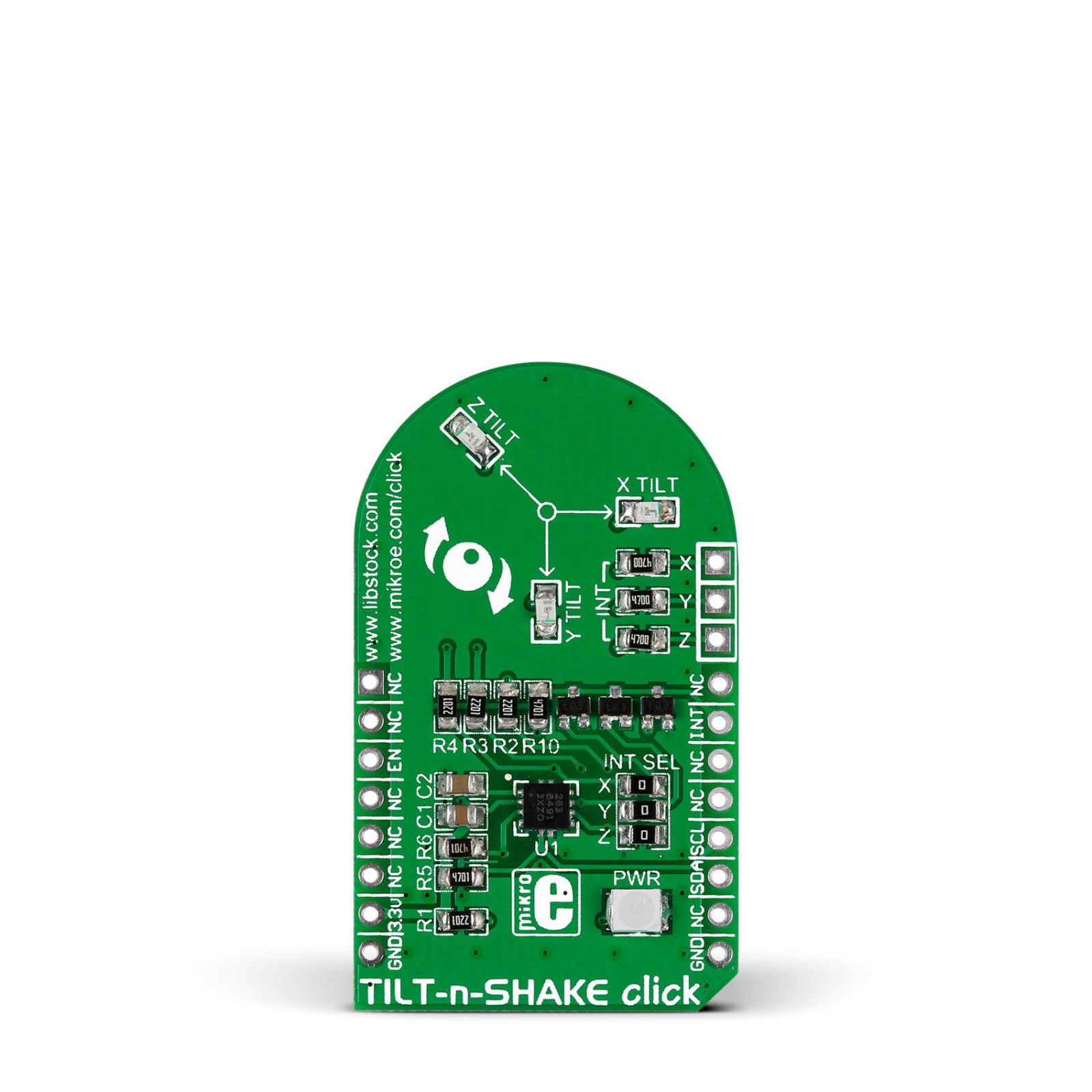
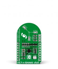
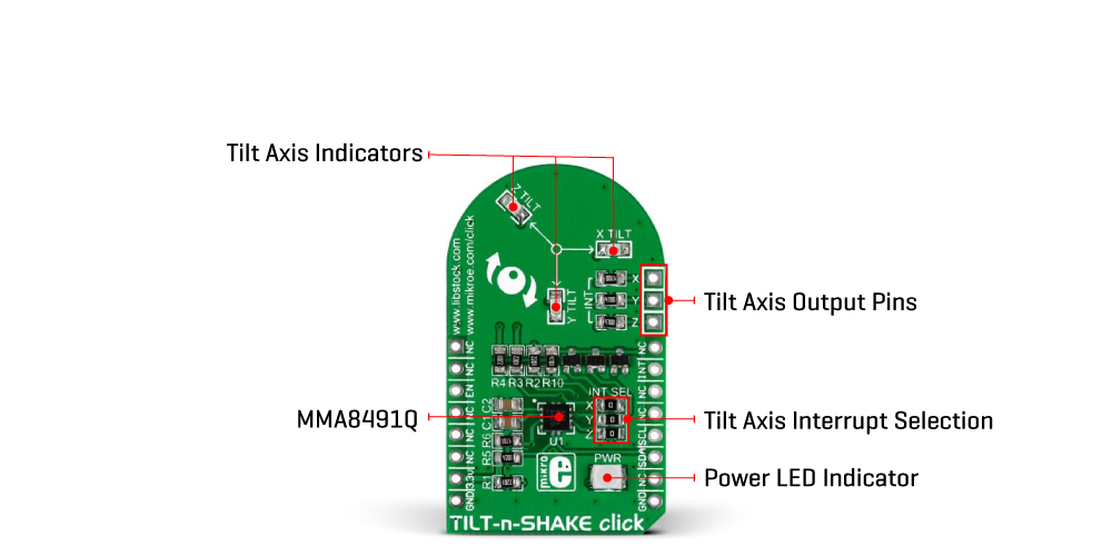
Tilt-n-Shake Click is based on the MMA8491Q, a multifunctional 3-axis digital accelerometer from NXP Semiconductors that enables the lowest power consumption for low data rate accelerometer applications. It can accommodate two accelerometer configurations, acting as a digital output accelerometer or a 45° tilt sensor with the addition of a visual indication of the tilt axis. The MMA8491Q is flexible and useful for various applications beyond smart metering in which orientation needs to be accurately measured and for tracking assets in business and industrial applications.
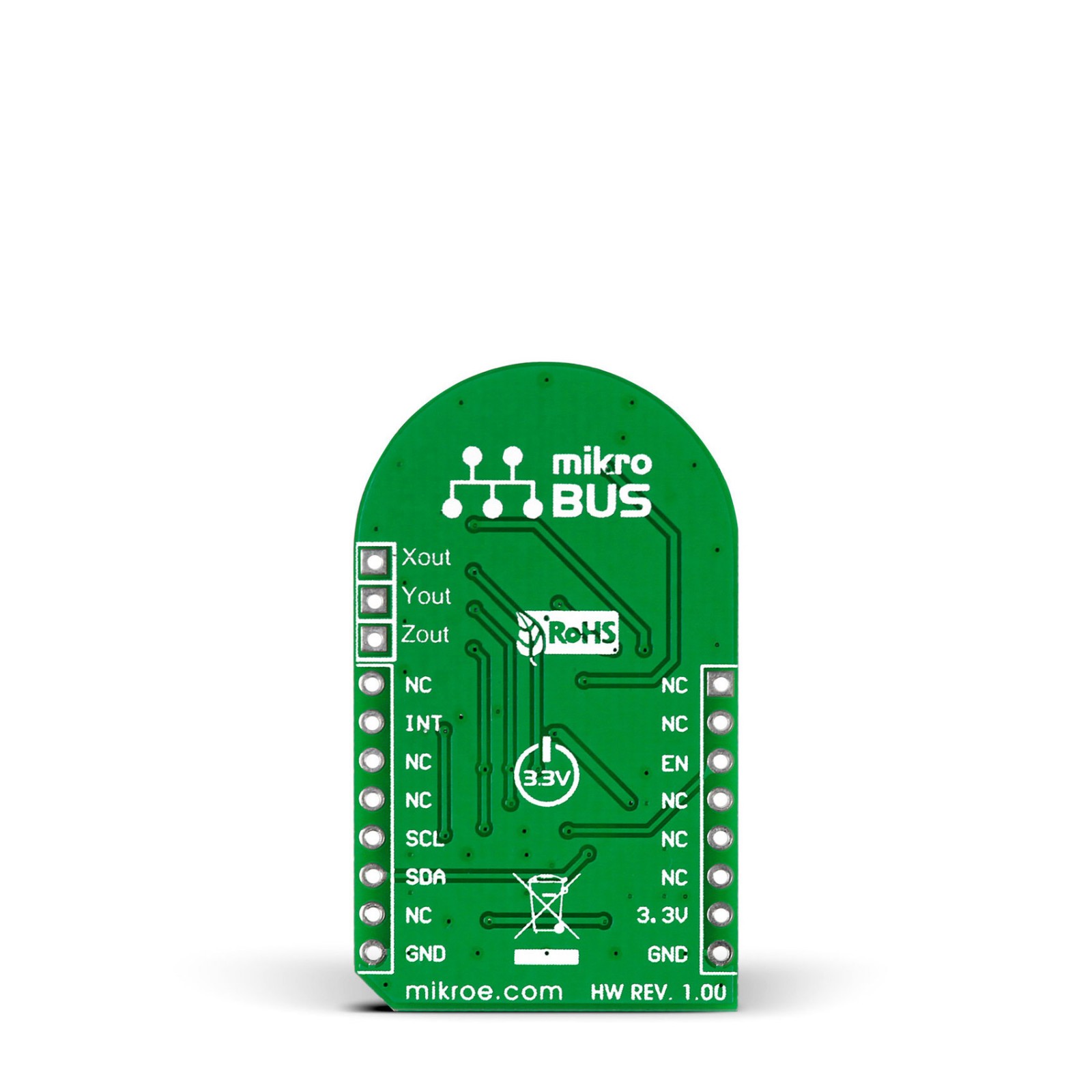
This Click board™ communicates with MCU using the standard I2C 2-Wire interface to read data and configure settings, supporting Fast Mode up to 400kHz. The MMA8491Q can be enabled or disabled through the EN pin routed to the CS pin of the mikroBUS™ socket, hence, offering a switch operation to turn ON/OFF the accelerometer system. Also, the MMA8491Q must be in an Active state of operation when the data is being polled (EN pin must be set in the high logic state).
The 14-bit ±8g accelerometer data can be read via the I2C 2-Wire interface with a 1 mg/LSB sensitivity. On the other hand, as a 45° tilt sensor, the MMA8491Q offers a single line output per axis through the X, Y, and Z pins. These pins are asserted whenever the tilt angle in the respective axis is greater than 45°. The information from these pins can be processed through the INT pin of the mikroBUS™ socket, allowing the user to select which tilt axes to detect, or it is also possible to use them externally in the configuration that best suits the user through an additional unpopulated tilt header. The population makes tilt axis information selection of corresponding X, Y, and Z jumpers marked with INT SEL. It is also possible to visually identify each of these axes through onboard yellow LEDs.
This Click board™ can be operated only with a 3.3V logic voltage level. The board must perform appropriate logic voltage level conversion before using MCUs with different logic levels. However, the Click board™ comes equipped with a library containing functions and an example code that can be used as a reference for further development.
Specifications
Type
Acceleration,Motion,Vibration
Applications
Can be used for information appliances, consumer electronics, household safety applications, remote control, and more
On-board modules
MMA8491Q – multifunctional 3-axis digital accelerometer from NXP Semiconductors
Key Features
Low power consumption, fast data output, tilt sensing, resolution and sensitivity, visual tilt indication, high performance, I2C interface, and more
Interface
I2C
Feature
No ClickID
Compatibility
mikroBUS™
Click board size
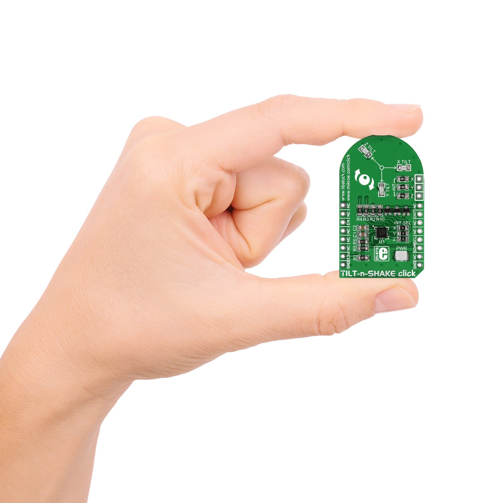
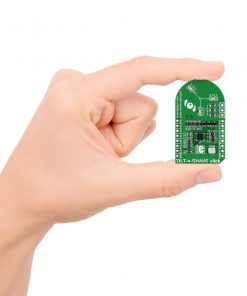
M (42.9 x 25.4 mm)
Input Voltage
3.3V
Pinout diagram
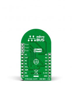
This table shows how the pinout on TILTnSHAKE Click corresponds to the pinout on the mikroBUS™ socket (the latter shown in the two middle columns).
Onboard settings and indicators
Label | Name | Default | Description |
---|---|---|---|
LD1 | PWR | – | Power LED Indicator |
LD2-LD3 | X-Y-Z TILT | – | Tilt Axis LED Indicators |
J1-J3 | INT SEL | – | Tilt Axis Interrupt Selection |
TILTnSHAKE Click electrical specifications
Description | Min | Typ | Max | Unit |
---|---|---|---|---|
Supply Voltage | – | 3.3 | – | V |
Acceleration Range | – | ±8 | – | g |
Sensitivity | – | 1 | – | mg/LSB |
Resolution | – | 14 | – | bit |
Tilt Angle | – | 45 | – | deg |
Software Support
We provide a library for the TILT-n-SHAKE Click as well as a demo application (example), developed using MikroElektronika compilers. The demo can run on all the main MikroElektronika development boards.
Package can be downloaded/installed directly from NECTO Studio Package Manager(recommended way), downloaded from our LibStock™ or found on Mikroe github account.
Library Description
This library contains API for TILT-n-SHAKE Click driver.
Key functions
-
Function for read status and axis
-
Function for conversion
-
Function for enabled chip
Example Description
This application is multifunctional 3-axis digital accelerometer that can also be configured as a 45-degree Tilt sensor.
void application_task ( )
{
uint8_t tiltnshake_status;
float tiltnshake_out_x_float;
float tiltnshake_out_y_float;
float tiltnshake_out_z_float;
uint16_t tiltnshake_out_x;
uint16_t tiltnshake_out_y;
uint16_t tiltnshake_out_z;
tiltnshake_enable( &tiltnshake, TILTNSHAKE_ENABLE );
tiltnshake_read_status_and_axis( &tiltnshake, &tiltnshake_status, &tiltnshake_out_x, &tiltnshake_out_y, &tiltnshake_out_z );
tiltnshake_enable( &tiltnshake, TILTNSHAKE_DISABLE );
if ( tiltnshake_status == TILTNSHAKE_DATA_READY )
{
tiltnshake_conversion
(
&tiltnshake_out_x,
&tiltnshake_out_y,
&tiltnshake_out_z,
&tiltnshake_out_x_float,
&tiltnshake_out_y_float,
&tiltnshake_out_z_float
);
log_printf( &logger, " rn" );
log_printf( &logger, "X_out = %.2f rn", tiltnshake_out_x_float );
log_printf( &logger, "Y_out = %.2frn", tiltnshake_out_y_float );
log_printf( &logger, "Z_out = %.2frn", tiltnshake_out_z_float );
log_printf( &logger, "-----------------------------------------------rn");
Delay_ms( 500 );
}
Delay_ms( 1700 );
}
The full application code, and ready to use projects can be installed directly from NECTO Studio Package Manager(recommended way), downloaded from our LibStock™ or found on Mikroe github account.
Other Mikroe Libraries used in the example:
- MikroSDK.Board
- MikroSDK.Log
- Click.TiltNshake
Additional notes and informations
Depending on the development board you are using, you may need USB UART click, USB UART 2 Click or RS232 Click to connect to your PC, for development systems with no UART to USB interface available on the board. UART terminal is available in all MikroElektronika compilers.
mikroSDK
This Click board™ is supported with mikroSDK – MikroElektronika Software Development Kit. To ensure proper operation of mikroSDK compliant Click board™ demo applications, mikroSDK should be downloaded from the LibStock and installed for the compiler you are using.
For more information about mikroSDK, visit the official page.