How does it work?
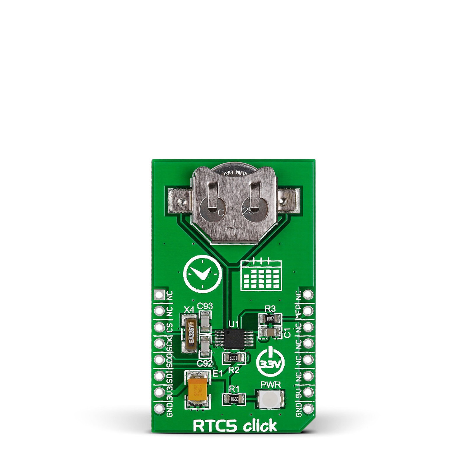
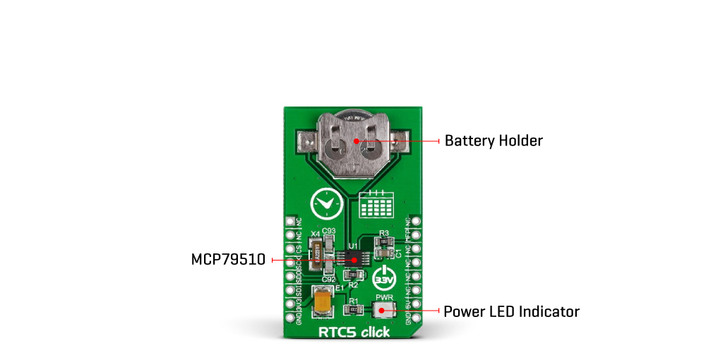
RTC 5 Click is based on the MCP79510, a low-power time-keeping device from Microchip, using internal counters for hours, minutes, seconds, hundredths of seconds, days, months, years, and days of the week. The MCP79510 is configured to transmit calendar and time data to the MCU (24-hour/12-hour format) based on a 32.768kHz quartz crystal and comes with an integrated interrupt generation function. It reads and writes time data from and to the MCU in units ranging from seconds to the last two digits of the calendar year. The calendar year will automatically be identified as a leap year when its last two digits are a multiple of 4. Consequently, leap years up to the year 2399 can automatically be recognized.
The MCP79510 is highly integrated with memory and advanced features usually found in much more expensive versions of RTC. It consists of digital trimming added for higher accuracy, a battery switchover for backup power, a timestamp to log power failures, and three types of memory, including 64 bytes of general-purpose SRAM, 1Kbit EEPROM, and a unique blank ID in a locked section of EEPROM.
SRAM and timekeeping circuitry are powered from the backup supply (button cell battery holder compatible with the 3000TR battery holder suitable for 12mm Coin Cell batteries) when main power is lost, allowing the device to maintain accurate time and the SRAM contents. Times during power transfer from primary to auxiliary and vice versa are both logged by the power-fail timestamp.
This Click board™ communicates with MCU through a standard SPI interface supporting the most common SPI mode, SPI Mode 0, with a maximum frequency of 5MHz. Besides, it also has a shared pin for outputting a selectable frequency square wave from 1 up to 32.768kHz, or alarm signals routed to the INT pin of the mikroBUS™ socket marked as MFP. Alarm signals can either generate an interrupt at a specific time in the future or generate a periodic interrupt every second, minute, hour, day, day of the week, or month.
This Click board™ can be operated only with a 3.3V logic voltage level. The board must perform appropriate logic voltage level conversion before using MCUs with different logic levels. However, the Click board™ comes equipped with a library containing functions and an example code that can be used as a reference for further development.
Specifications
Type
RTC
Applications
Can be used for general-consumer applications, including daily alarms, metering applications, and others requiring an accurate RTC for their operation
On-board modules
MCP79510 – real-time clock/calendar device from Microchip
Key Features
Low power consumption, backup supply, power-fail timestamp, high accuracy, clock/calendar feature, programmable interrupt and clock output, automatic leap year recognition, and more
Interface
GPIO,SPI
Feature
No ClickID
Compatibility
mikroBUS™
Click board size
M (42.9 x 25.4 mm)
Input Voltage
3.3V,5V
Pinout diagram
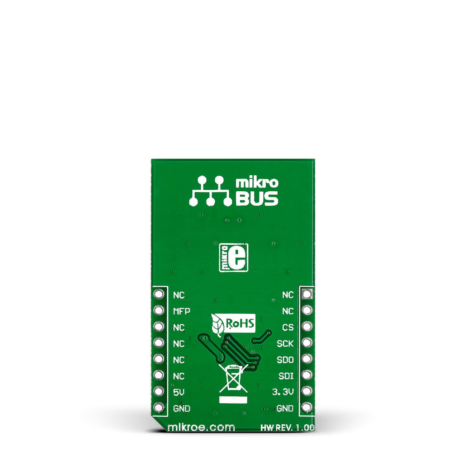
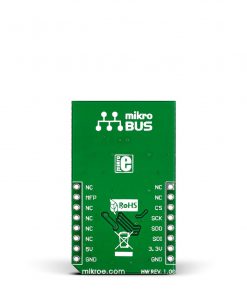
This table shows how the pinout on RTC 5 Click corresponds to the pinout on the mikroBUS™ socket (the latter shown in the two middle columns).
Onboard settings and indicators
Label | Name | Default | Description |
---|---|---|---|
LD1 | PWR | – | Power LED Indicator |
RTC 5 Click electrical specifications
Description | Min | Typ | Max | Unit |
---|---|---|---|---|
Supply Voltage | – | 3.3 | – | V |
Memory Size (SRAM) | – | – | 64 | bytes |
Memory Size (EEPROM) | – | – | 1 | Kbits |
Clock Output | – | – | 32 | kHz |
Software Support
We provide a library for the RTC5 Click as well as a demo application (example), developed using Mikroe compilers. The demo can run on all the main Mikroe development boards.
Package can be downloaded/installed directly from NECTO Studio Package Manager(recommended), downloaded from our LibStock™ or found on Mikroe github account.
Library Description
This library contains API for RTC5 Click driver.
Key functions
-
Set time hours, minutes and seconds function.
-
Set date hours, minutes and seconds function.
-
Get time and date function.
Example Description
This is a example which demonstrates the use of RTC 5 Click board.
void application_task ( void )
{
rtc5_get_time_and_date( &rtc5, &time_date_data );
if ( time_sec_new != time_date_data.sec )
{
log_printf( &logger, " Time : %02d:%02d:%02drn", time_date_data.hours, time_date_data.min, time_date_data.sec );
display_log_day_of_the_week( time_date_data.w_day );
log_printf( &logger, " Date : %02d.%02d.20%02d.rn", time_date_data.day, time_date_data.month, time_date_data.year );
log_printf( &logger, "--------------------rn" );
time_sec_new = time_date_data.sec;
}
}
The full application code, and ready to use projects can be installed directly from NECTO Studio Package Manager(recommended), downloaded from our LibStock™ or found on Mikroe github account.
Other Mikroe Libraries used in the example:
- MikroSDK.Board
- MikroSDK.Log
- Click.Rtc5
Additional notes and informations
Depending on the development board you are using, you may need USB UART click, USB UART 2 Click or RS232 Click to connect to your PC, for development systems with no UART to USB interface available on the board. UART terminal is available in all Mikroe compilers.
mikroSDK
This Click board™ is supported with mikroSDK – Mikroe Software Development Kit. To ensure proper operation of mikroSDK compliant Click board™ demo applications, mikroSDK should be downloaded from the LibStock and installed for the compiler you are using.
For more information about mikroSDK, visit the official page.