How does it work?
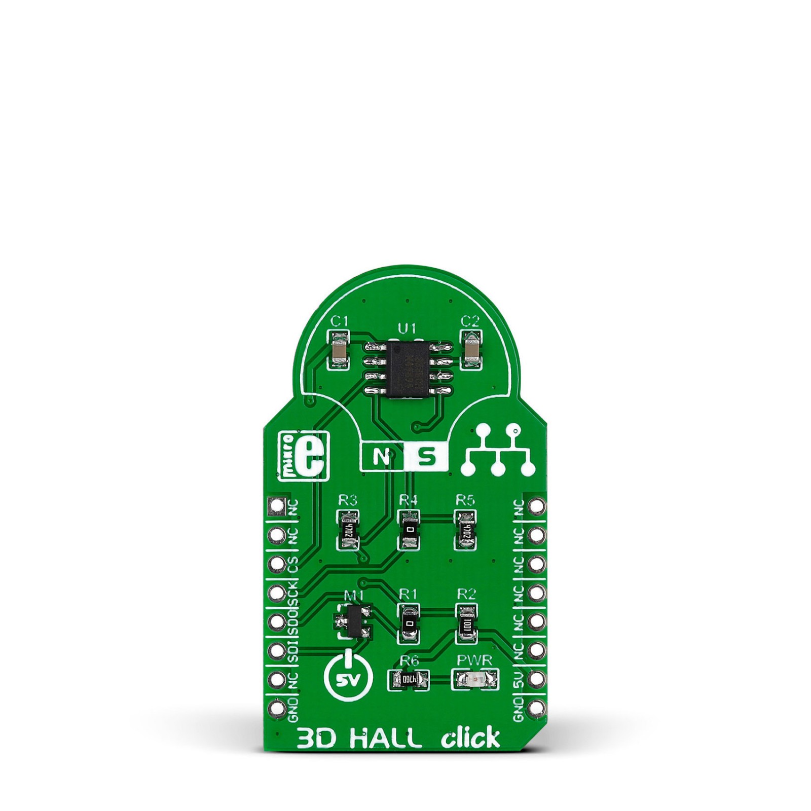
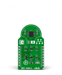
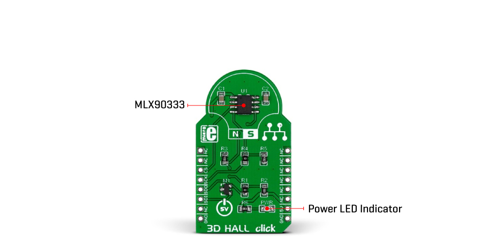
3D Hall Click is based on the MLX90333, a Triaxis® contactless position sensor from Melexis Technologies able to sense any magnet moving in its surrounding through the measurement and the processing of the three spatial components of the magnetic flux density vector (Bx, By, and Bz). The horizontal components (Bx and By) are sensed thanks to an Integrated Magneto-Concentrator (IMC), while the vertical component (Bz) is sensed through a conventional Hall plate. Thanks to its excellent performance, the MLX90333 can measure its rotational, linear, and 3D displacement with high precision.
The MLX90333 features a 3D magnetometer mode for which the 3D information of the magnetic flux density is reported to a host controller through an SPI interface supporting the most common SPI mode, SPI Mode 1, with a maximum frequency of 20MHz. The output transfer characteristic is fully programmable (e.g., offset, gain, clamping levels, linearity, thermal drift, filtering, range, and such) to match any specific requirement through end-of-line calibration.
This Click board™ can be operated only with a 5V logic voltage level. The board must perform appropriate logic voltage level conversion before using MCUs with different logic levels. However, the Click board™ comes equipped with a library containing functions and an example code that can be used as a reference for further development.
Specifications
Type
Magnetic
Applications
Can be used for rotary, linear, and 3D/joystick position sensing applications
On-board modules
MLX90333 – contactless position sensor from Melexis Technologies
Key Features
Absolute 3D positioning, Triaxis® Hall technology, SPI interface, programmable linear transfer characteristics (alpha, beta), high angular resolution, sensitive to the three components of the flux density, and more
Interface
SPI
Feature
No ClickID
Compatibility
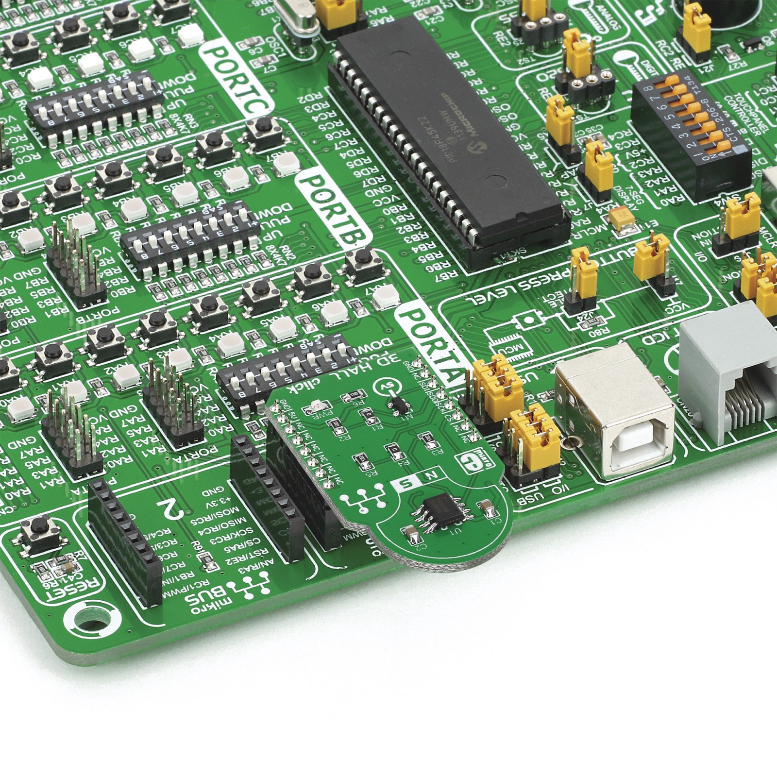
mikroBUS™
Click board size
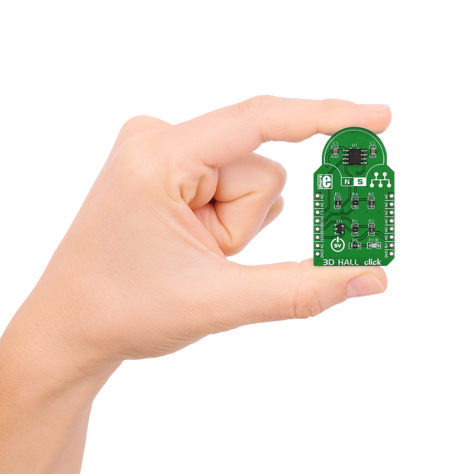
M (42.9 x 25.4 mm)
Input Voltage
5V
Pinout diagram
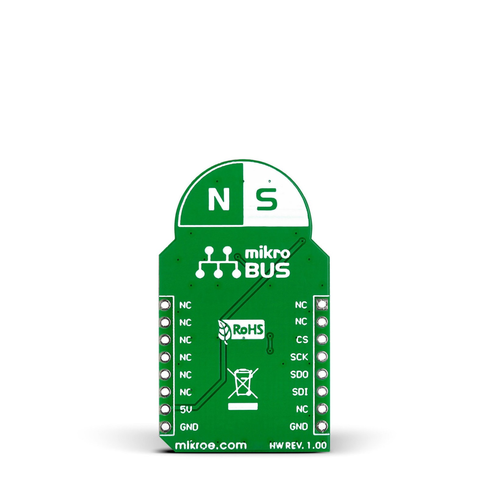
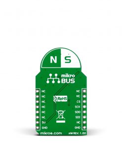
This table shows how the pinout on 3D Hall Click corresponds to the pinout on the mikroBUS™ socket (the latter shown in the two middle columns).
Onboard settings and indicators
Label | Name | Default | Description |
---|---|---|---|
LD1 | PWR | – | Power LED Indicator |
3D Hall Click electrical specifications
Description | Min | Typ | Max | Unit |
---|---|---|---|---|
Supply Voltage | – | 5 | – | V |
Sensning Range (X,Y) | 20 | – | 70 | mT |
Sensning Range (Z) | 24 | – | 140 | mT |
Resolution | – | 12 | – | bit |
Software Support
We provide a library for the 3D Hall Click as well as a demo application (example), developed using MikroElektronika compilers. The demo can run on all the main MikroElektronika development boards.
Package can be downloaded/installed directly from NECTO Studio Package Manager(recommended way), downloaded from our LibStock™ or found on Mikroe github account.
Library Description
This library contains API for 3D Hall Click driver.
Key functions
-
Read 8 bytes data from sensor function.
-
Calculate angle function.
Example Description
This application use to determine angle position.
void application_task ( void )
{
c3dhall_all_data_t all_data;
uint8_t angle_alpha;
uint8_t angle_beta;
c3dhall_read_all_data( &c3dhall, &all_data );
Delay_100ms( );
if ( ( all_data.data_error ) == C3DHALL_NO_ERRORS )
{
angle_alpha = c3dhall_calculate_angle( &c3dhall, all_data.data_angle_a );
angle_beta = c3dhall_calculate_angle( &c3dhall, all_data.data_angle_b );
log_printf( &logger, " Alpha : %urn", ( uint16_t ) angle_alpha );
log_printf( &logger, " Beta : %urn", ( uint16_t ) angle_beta );
log_printf( &logger, "-------------------------rn", angle_beta );
}
else
{
if ( all_data.data_error == C3DHALL_F_ADCMONITOR )
log_printf( &logger, " ADC Failure rn" );
else if ( all_data.data_error == C3DHALL_F_ADCSATURA )
log_printf( &logger, " Electrical failure rn" );
else if ( all_data.data_error == C3DHALL_F_GAINTOOLOW )
log_printf( &logger, " Gain code is less rn" );
else if ( all_data.data_error == C3DHALL_F_GAINTOOHIGH )
log_printf( &logger, " Gain code is greater rn" );
else if ( all_data.data_error == C3DHALL_F_NORMTOOLOW )
log_printf( &logger, " Fast norm below 30 rn" );
else if ( all_data.data_error == C3DHALL_F_FIELDTOOLOW )
log_printf( &logger, " The norm is less rn" );
else if ( all_data.data_error == C3DHALL_F_FIELDTOOHIGH )
log_printf( &logger, " The norm is greater rn" );
else if ( all_data.data_error == C3DHALL_F_ROCLAMP )
log_printf( &logger, " Analog Chain Rough off rn" );
else if ( all_data.data_error == C3DHALL_F_DEADZONEALPHA )
log_printf( &logger, " Angle ALPHA in deadzone rn" );
else if ( all_data.data_error == C3DHALL_F_DEADZONEBETA )
log_printf( &logger, " Angle BETA in deadzone rn" );
else if ( all_data.data_error == C3DHALL_MULTIPLE_ERRORS )
log_printf( &logger, " More than one error rn" );
else
log_printf( &logger, " Unknown error rn" );
log_printf( &logger, "-------------------------rn" );
Delay_1sec( );
}
}
The full application code, and ready to use projects can be installed directly from NECTO Studio Package Manager(recommended way), downloaded from our LibStock™ or found on Mikroe github account.
Other Mikroe Libraries used in the example:
- MikroSDK.Board
- MikroSDK.Log
- Click.3DHall
Additional notes and informations
Depending on the development board you are using, you may need USB UART click, USB UART 2 Click or RS232 Click to connect to your PC, for development systems with no UART to USB interface available on the board. UART terminal is available in all MikroElektronika compilers.
mikroSDK
This Click board™ is supported with mikroSDK – MikroElektronika Software Development Kit. To ensure proper operation of mikroSDK compliant Click board™ demo applications, mikroSDK should be downloaded from the LibStock and installed for the compiler you are using.
For more information about mikroSDK, visit the official page.