How does it work?
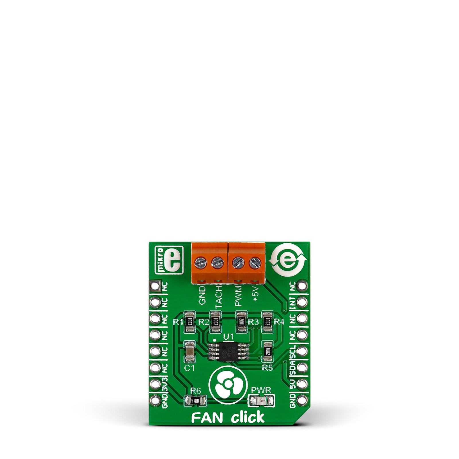
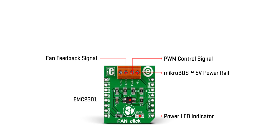
Fan Click is based on the EMS2301, a single/multiple RPM-based PWM fan controller from Microchip. The EMS2301 uses a programmable frequency driver and RPM-based algorithm with an internal clock to allow you to regulate the RPM of a given fan with 1% accuracy from 500 to 16K RPM. It also provides tachometer feedback for fan speed control available on TACH onboard terminal. The Fan Click can operate in either a closed-loop fashion or as a directly PWM-controlled device. In a closed loop, the Fan Speed Control (FSC) algorithm can detect aging, stalled, or locked fans and will trigger an interrupt. In the FSC mode user determines a target tachometer count, and the PWM drive setting is automatically updated to achieve this target speed.
This Click board™ communicates with MCU using the standard I2C 2-Wire interface to read data and configure settings, supporting a Fast Mode operation up to 400kHz. The EMS2301 monitors the fans’ tachometer signals to detect fan failure, and when the tachometer count is larger than the fan tachometer limit, the fan is considered failing. If that happens, the alert is triggered over the interrupt INT pin. Meanwhile, the fan driver attempts to alleviate a Stalled/Stack fan condition. Although a 3.3V voltage level only, this Click board™ uses a 5V rail to power a 4-wire fan over a 4-pin screw terminal. This board does not support an external power supply for the fan.
This Click board™ can only be operated with a 3.3V logic voltage level. The board must perform appropriate logic voltage level conversion before using MCUs with different logic levels. However, the Click board™ comes equipped with a library containing functions and an example code that can be used as a reference for further development.
Specifications
Type
Brushless
Applications
Can be used for controlling four-wire fans inside various electronics
On-board modules
EMS2301 – single/multiple RPM-based PWM fan controller from Microchip
Key Features
For controlling 5V 4-wire fans, interrupt for alerting of stalled and stuck fans, internal clock for regulating RPM of fan, optional detection of aging fans, I2C interface, low and high speed PWM, low power consumption, and more
Interface
I2C
Feature
No ClickID
Compatibility
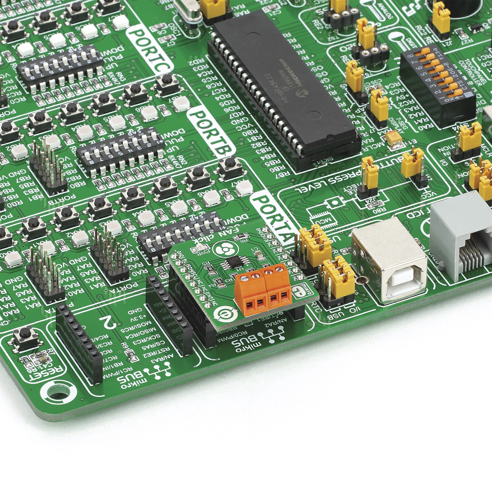
mikroBUS™
Click board size
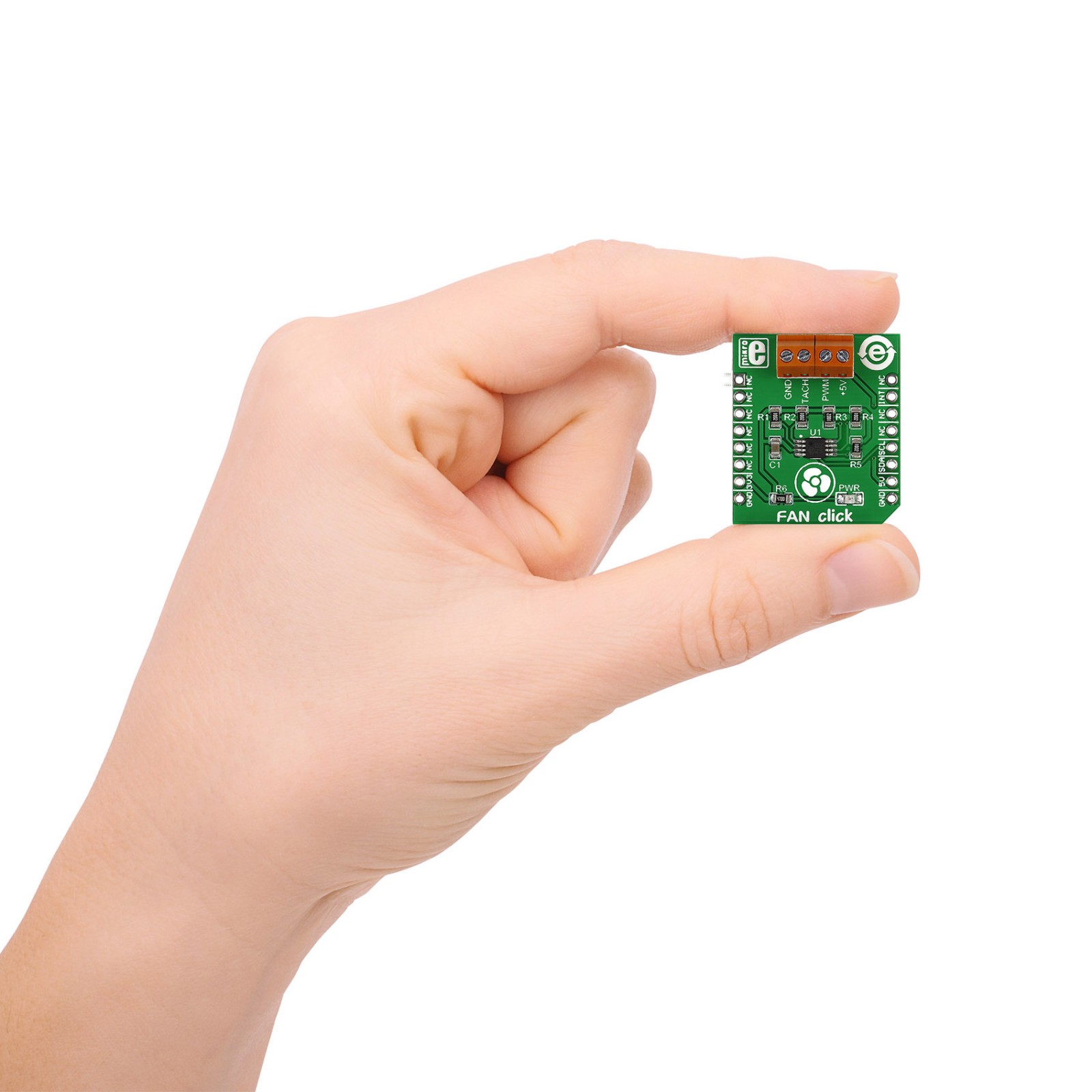
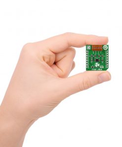
S (28.6 x 25.4 mm)
Input Voltage
3.3V,5V
Pinout diagram
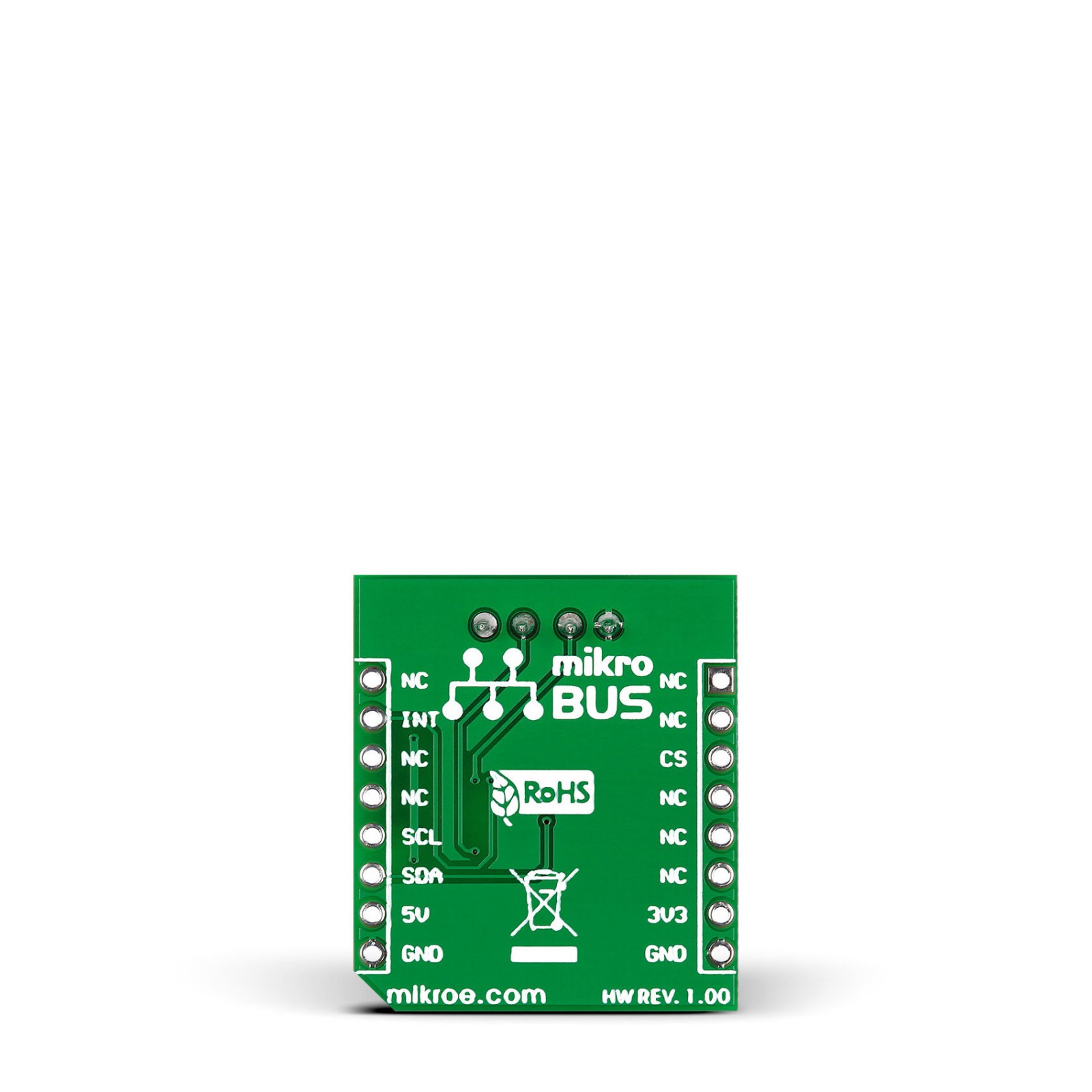
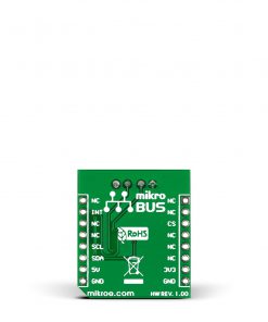
This table shows how the pinout on Fan Click corresponds to the pinout on the mikroBUS™ socket (the latter shown in the two middle columns).
Onboard settings and indicators
Label | Name | Default | Description |
---|---|---|---|
– | PWR | – | Power LED Indicator |
Fan Click electrical specifications
Description | Min | Typ | Max | Unit |
---|---|---|---|---|
Supply Voltage | – | 3.3 | – | V |
Fan Supply Voltage | – | 5 | – | V |
Output Current | – | 350 | – | mA |
Resolution | – | 256 | – | steps |
PWM Frequency | 9.5 | – | 29 | kHz |
Software Support
We provide a library for the Fan Click as well as a demo application (example), developed using Mikroe compilers. The demo can run on all the main Mikroe development boards.
Package can be downloaded/installed directly from NECTO Studio Package Manager(recommended), downloaded from our LibStock™ or found on Mikroe github account.
Library Description
This library contains API for Fan Click driver.
Key functions
-
Generic write function.
-
Generic read function.
-
Fan click lock registers.
Example Description
This application is controller for powering and regulating.
void application_task ( void )
{
for ( uint8_t duty = FAN_DUTY_RATIO_0_PER; duty <= FAN_DUTY_RATIO_100_PER;
duty += FAN_DUTY_RATIO_10_PER )
{
fan_setting( &fan, duty );
log_printf( &logger, " Duty Ratio : %u%%rn", (uint16_t)duty );
Delay_ms( 2000 );
uint16_t tacho = 0;
fan_get_tach( &fan, &tacho );
log_printf( &logger, " Rotation per minute : %urpmrnn", tacho );
Delay_ms( 2000 );
}
}
The full application code, and ready to use projects can be installed directly from NECTO Studio Package Manager(recommended), downloaded from our LibStock™ or found on Mikroe github account.
Other Mikroe Libraries used in the example:
- MikroSDK.Board
- MikroSDK.Log
- Click.Fan
Additional notes and informations
Depending on the development board you are using, you may need USB UART click, USB UART 2 Click or RS232 Click to connect to your PC, for development systems with no UART to USB interface available on the board. UART terminal is available in all Mikroe compilers.
mikroSDK
This Click board™ is supported with mikroSDK – Mikroe Software Development Kit. To ensure proper operation of mikroSDK compliant Click board™ demo applications, mikroSDK should be downloaded from the LibStock and installed for the compiler you are using.
For more information about mikroSDK, visit the official page.