RTC 6 Click
R455.00 R190.00 ex. VAT
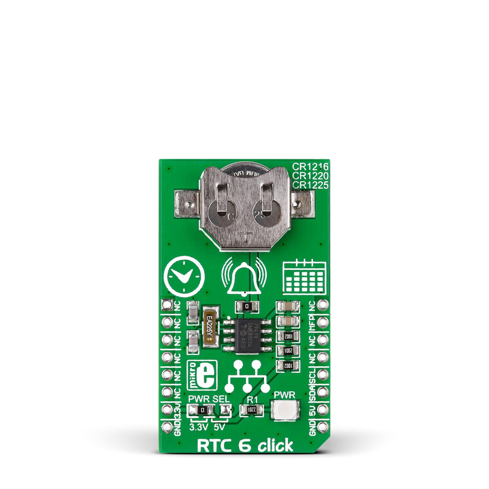
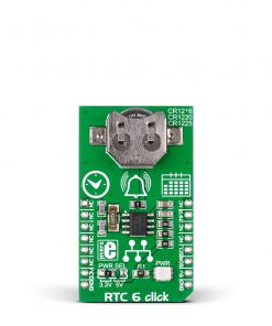
RTC 6 Click is a compact add-on board that keeps track of time in various applications. This board features the MCP79410, a battery-backed I2C real-time clock/calendar with SRAM, and protected EEPROM from Microchip. The RTC 6 Click tracks hours, minutes, seconds, days, months, years, and weekdays, with leap year compensation until 2399. The clock frequency is derived from an onboard 32.768KHz crystal oscillator. A coin-cell Lithium battery supplies backup power. This Click board™ makes the perfect solution for developing the IoT, wearable and portable devices, logging devices, industrial and health-related time metering applications, and all the other applications that require an accurate time base for various purposes.
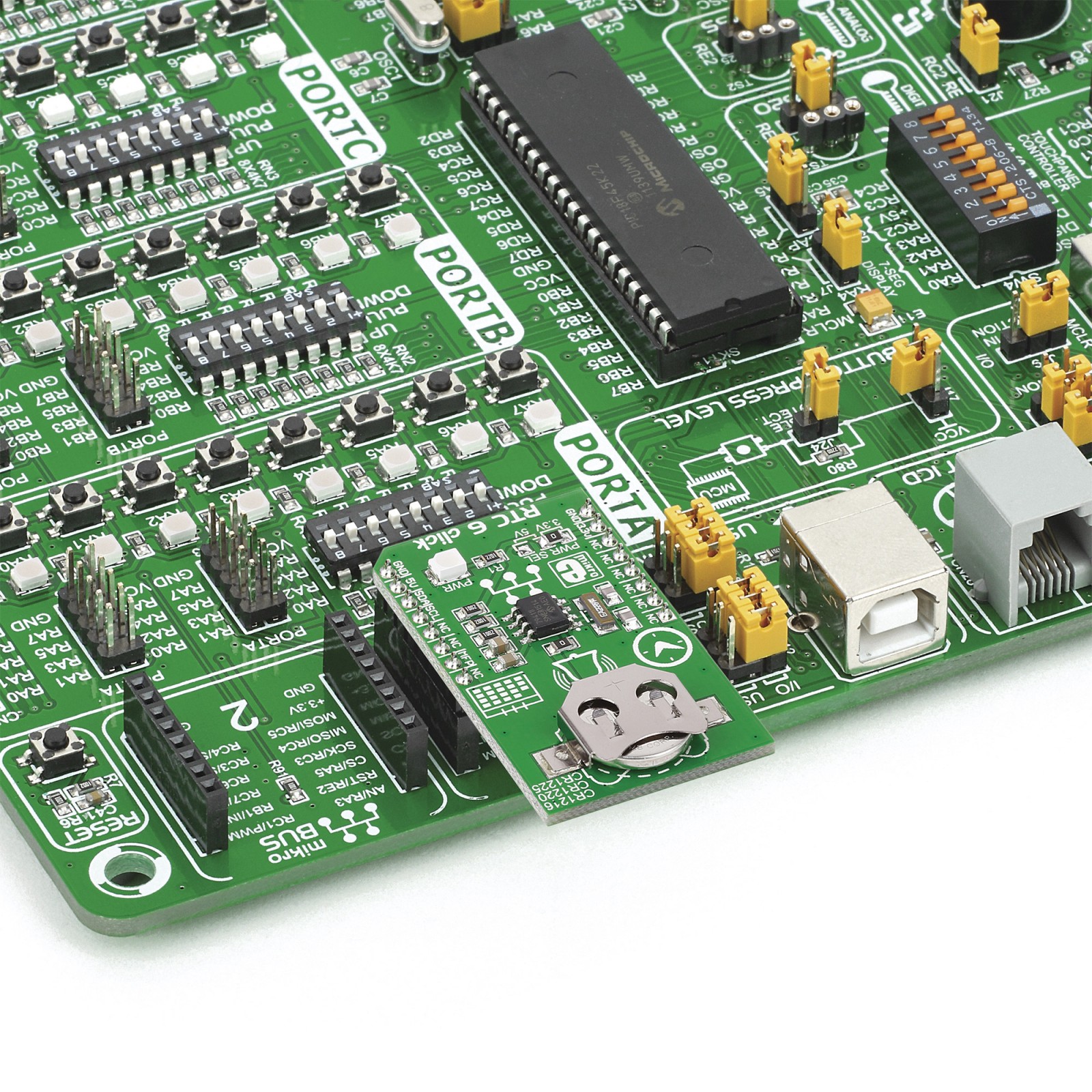
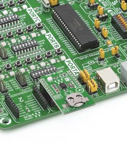
RTC 6 Click is supported by a mikroSDK compliant library, which includes functions that simplify software development. This Click board™ comes as a fully tested product, ready to be used on a system equipped with the mikroBUS™ socket.
Stock: 7 available immediately.
How does it work?
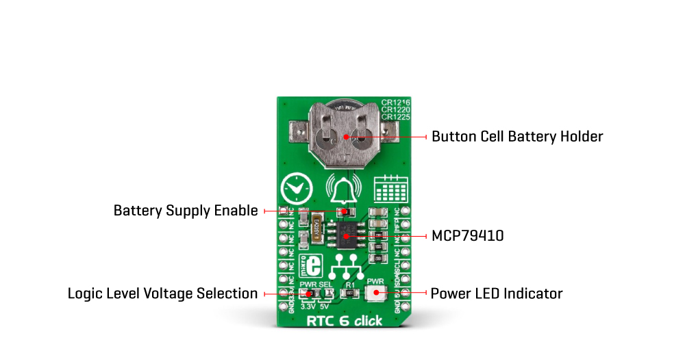
RTC 6 Click is based on the MCP79410, a battery-backed I2C real-time clock/calendar with SRAM, and protected EEPROM from Microchip. The alarms on this RTC 6 Click can be configured on all counters up to and including months. The clock frequency is delivered from an onboard 32.768KHz crystal oscillator. On-chip digital trimming with ±1 ppm resolution and ±129 ppm range can be used to adjust for frequency variance caused by crystal tolerance and temperature. For backup power for the RTC, this Click board™ features the coin-cell Lithium battery holder that supports CR1216, CR1220, and CR1225 battery formats. By removing the 0ohm resistor, you can disable battery backup.
For storing data, the MCP79411 has 64 bytes of battery-backed SRAM that correlate with the timekeeping circuit and allow the device to maintain accurate time and date when main power is lost. The time between power switches, from backup to primary power and vice versa, is restored is recorded by the power outage time stamp. The MCP79411 features 1Kbit of internal nonvolatile EEPROM with software write protectable regions. An additional 64 bits of protected nonvolatile memory is only writable after an unlock sequence, making it ideal for storing a unique ID or other critical information.
The RTC 6 Click uses an I2C interface for communication with the host MCU, with a clock rate of up to 400KHz. This Click board™ also features a multifunction pin, accessible over the MFP pin of the mikroBUS™ socket. The multifunctional output on this pin can be configured to assert an alarm match to output a selectable frequency square wave or as a general-purpose output. The MCP79411 features two independent alarms. Each alarm can be used to either generate an interrupt at a specific time in the future or to generate a periodic interrupt every minute, hour, day, day of week, or month.
This Click board™ can operate with either 3.3V or 5V logic voltage levels selected via the PWR SEL jumper. This way, both 3.3V and 5V capable MCUs can use the communication lines properly. However, the Click board™ comes equipped with a library containing easy-to-use functions and an example code that can be used, as a reference, for further development.
Specifications
Type
RTC
Applications
Can be used for the development of the IoT, wearable and portable devices, logging devices, industrial and health-related time metering applications, and all the other applications that require an accurate time base for various purposes
On-board modules
MCP79410 – battery-backed I2C real-time clock/calendar with SRAM, and protected EEPROM from Microchip
Key Features
Tracks hours, minutes, seconds, days, months, years, and weekdays, with leap year compensation until the year 2399, battery backup support, 64 bytes of battery-backed SRAM and 1Kbit of EEPROM, and more
Interface
I2C
Feature
No ClickID
Compatibility
mikroBUS™
Click board size
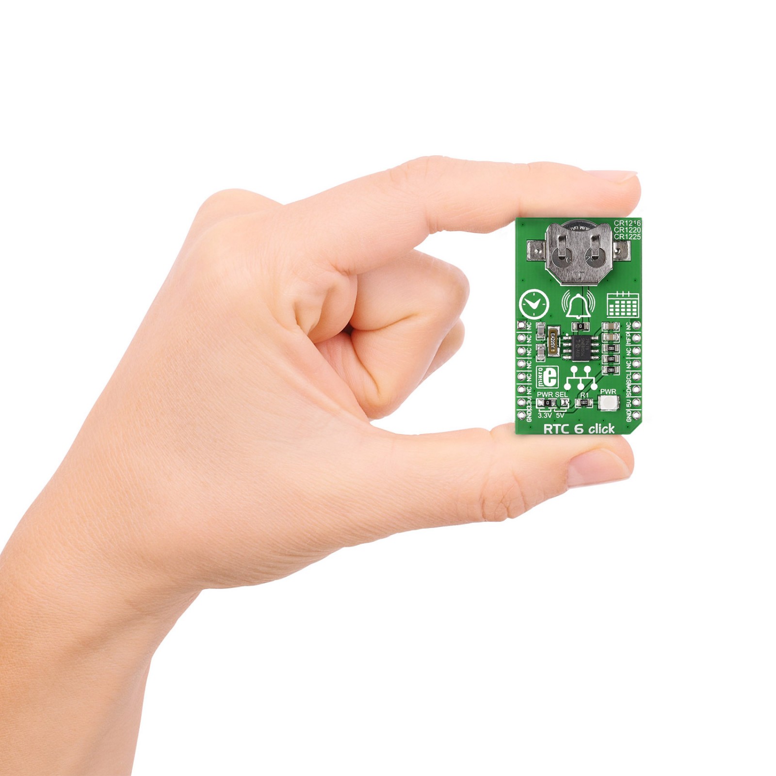
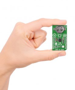
M (42.9 x 25.4 mm)
Input Voltage
3.3V or 5V
Pinout diagram
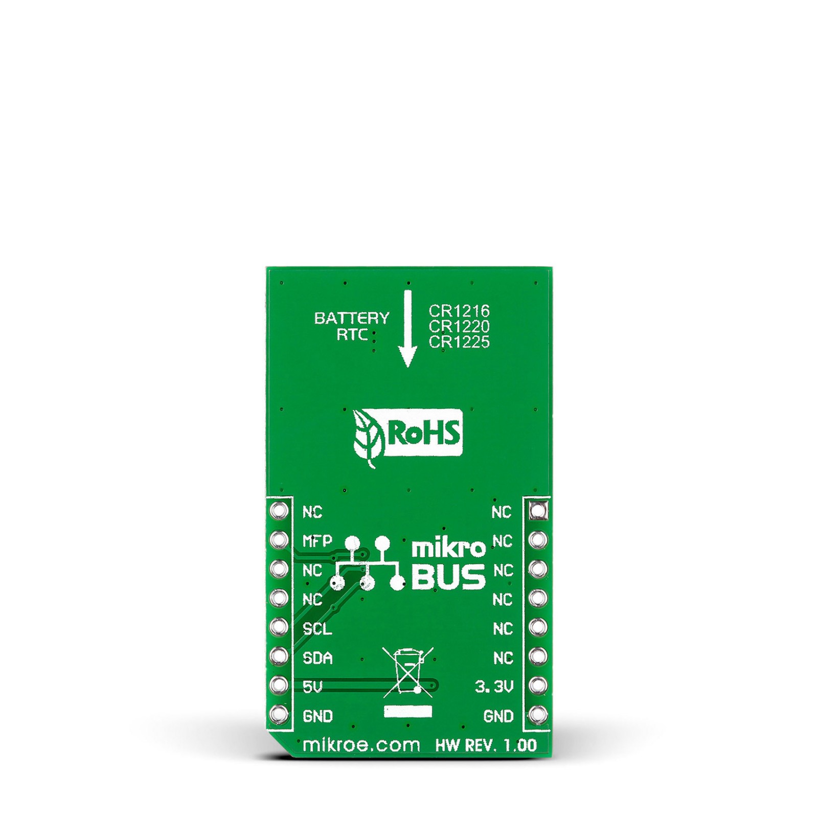
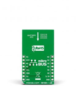
This table shows how the pinout on RTC 6 Click corresponds to the pinout on the mikroBUS™ socket (the latter shown in the two middle columns).
Onboard settings and indicators
| Label | Name | Default | Description |
|---|---|---|---|
| – | PWR | – | Power LED Indicator |
| – | PWR SEL | Left | Logic Level Voltage Selection 3V3/5V: Left position 3V3, Right position 5V |
| R5 | – | Populated | Battery Supply Enable Jumper |
RTC 6 Click electrical specifications
| Description | Min | Typ | Max | Unit |
|---|---|---|---|---|
| Supply Voltage | 3.3 | – | 5 | V |
| Backup Voltage | – | 3 | – | V |
| Date Format | YY-MM-DD-dd | |||
| Date Format | HH:MM:SS:hh | |||
| Memory Size | – | – | 64 | byte |
Software Support
We provide a library for the RTC 6 Click as well as a demo application (example), developed using MIKROE compilers. The demo can run on all the main MIKROE development boards.
Package can be downloaded/installed directly from NECTO Studio Package Manager (recommended), downloaded from our LibStock™ or found on MIKROE github account.
Library Description
This library contains API for RTC 6 Click driver.
Key functions
-
This function enables automatic switch to battery on VCC failure.
-
This function gets current GMT time and sets it in the RTC.
-
his function calculates current local time.
Example Description
This application enables usage of Real-TIme clock and calendar with alarm on RTC 6 click.
 void application_task ( void )
 {
     //  Task implementation.

     rtc6_get_gmt_time( &rtc6, &utc_time );
     rtc6_get_local_time( &rtc6, &local_time );

     log_printf( &logger, "--- UTC time ---rnTime : %d %d %drn", utc_time.hours, utc_time.minutes, utc_time.seconds );

     log_printf( &logger, "Date : %d %d %drn", utc_time.monthday, utc_time.month, utc_time.year );

     log_printf( &logger, "--- Local time ---rnTime : %d %d %drn", local_time.hours, local_time.minutes, local_time.seconds );

     log_printf( &logger, "Date : %d %d %drn rn", local_time.monthday, local_time.month, local_time.year );

     if ( rtc6_is_active_alarm( &rtc6 ) != 0 )
     {
         log_printf( &logger, " ----- Active alarm ----- rn" );
         rtc6_disable_alarm( &rtc6, RTC6_ALARM_0 );
         rtc6_repeat_alarm( &rtc6, RTC6_ALARM_0, 20 );
     }

     Delay_ms( 900 );
 }
The full application code, and ready to use projects can be installed directly from NECTO Studio Package Manager (recommended), downloaded from our LibStock™ or found on MIKROE github account.
Other MIKROE Libraries used in the example:
- MikroSDK.Board
- MikroSDK.Log
- Click.Rtc6
Additional notes and informations
Depending on the development board you are using, you may need USB UART click, USB UART 2 Click or RS232 Click to connect to your PC, for development systems with no UART to USB interface available on the board. UART terminal is available in all MIKROE compilers.
mikroSDK
This Click board™ is supported with mikroSDK – MIKROE Software Development Kit, that needs to be downloaded from the LibStock and installed for the compiler you are using to ensure proper operation of mikroSDK compliant Click board™ demo applications.
For more information about mikroSDK, visit the official page.
Resources
Downloads
| Weight | 27 g |
|---|---|
| Brand | MikroElektronika |

