How does it work?
Accel 3 Click is based on the H3LIS331DL, a low-power, high-g 3-axis digital accelerometer from STMicroelectronics. The proprietary process technology allows the processing of suspended silicon structures, which are attached to the substrate in a few points called anchors, free to move in the direction of the sensed acceleration. When acceleration is applied to the sensor, the proof mass displaces from its nominal position, causing an imbalance in the capacitive half bridge. This imbalance is measured using charge integration in response to a voltage pulse applied to the capacitor. The sensors interface is factory calibrated for sensitivity and zero-g level. The trim values are stored inside the device in non-volatile memory. Any time the device is turned on, the trim parameters are downloaded into the registers to be used during active operation, allowing the device to be used without further calibration.
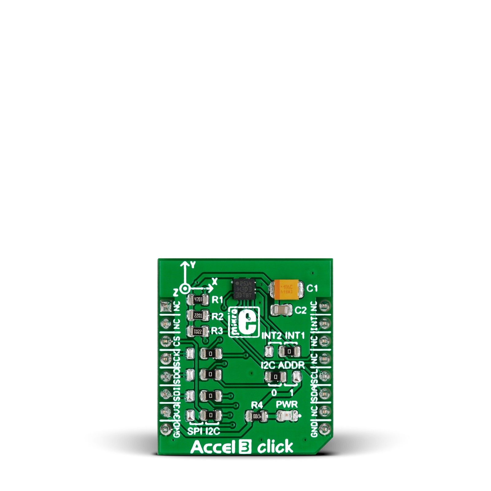
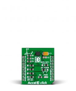
The acceleration data of Accel 3 Click is accessed through I2C or SPI interface, with a 400KHz fast mode frequency for I2C, and a 10MHz clock frequency for SPI communication. The selection is made by positioning four SMD jumpers labeled SPI I2C in an appropriate position, with the I2C set by default. Note that all the jumpers’ positions must be on the same side, or the Click board™ may become unresponsive. While the I2C interface is selected, the H3LIS331DL allows choosing the least significant bit (LSB) of its I2C slave address using the SMD jumper labeled I2C ADDR (0 set by default).
The H3LIS331DL also possesses two inertial interrupts, both accessible over the INT2 INT1 jumper and INT pin of the mikroBUS™ socket. The user can completely program the functions, threshold, and timing of the two interrupt signals through the selected interface. They signal the host MCU that a motion event has been sensed.
This Click board™ can only be operated with a 3.3V logic voltage level. The board must perform appropriate logic voltage level conversion before using MCUs with different logic levels. However, the Click board™ comes equipped with a library containing functions and an example code that can be used as a reference for further development.
Specifications
Type
Acceleration,Motion
Applications
Can be used for developing multiple applications such as motion-activated functions, impact and shock detection, medical IoT applications, and more
On-board modules
H3LIS331DL – low-power high-g 3-axis digital accelerometer from STMicroelectronics
Key Features
A dynamically selectable full scale measurement range, 16-bit resolution, sleep-to-wakeup function, ultra-low power consumption, high-shock survivability, selectable interface, event monitoring, and more
Interface
I2C,SPI
Feature
No ClickID
Compatibility
mikroBUS™
Click board size
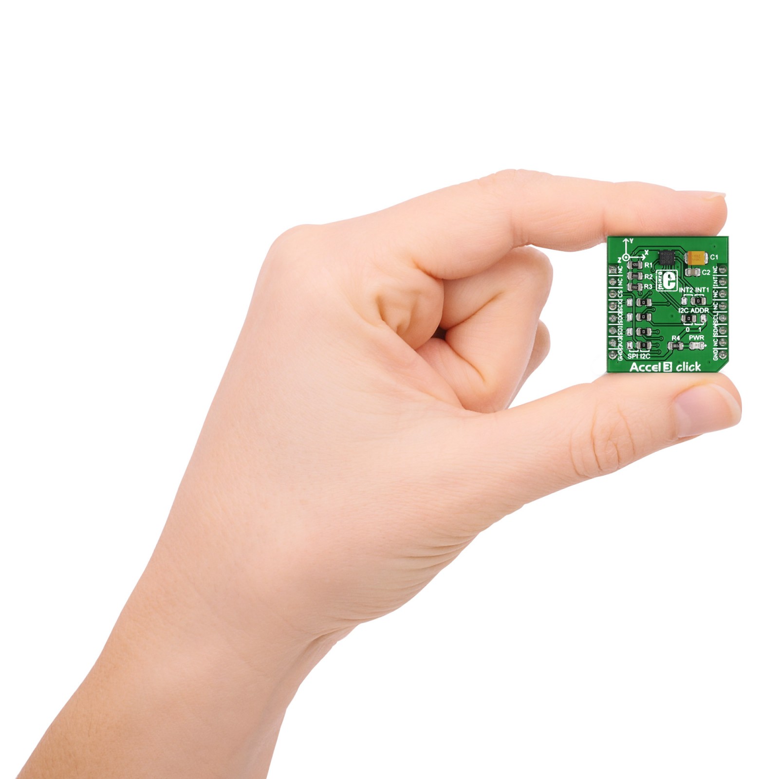
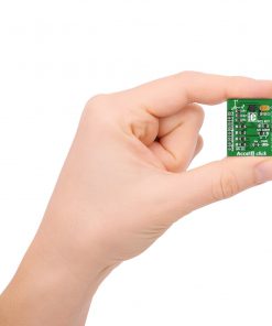
S (28.6 x 25.4 mm)
Input Voltage
3.3V
Pinout diagram
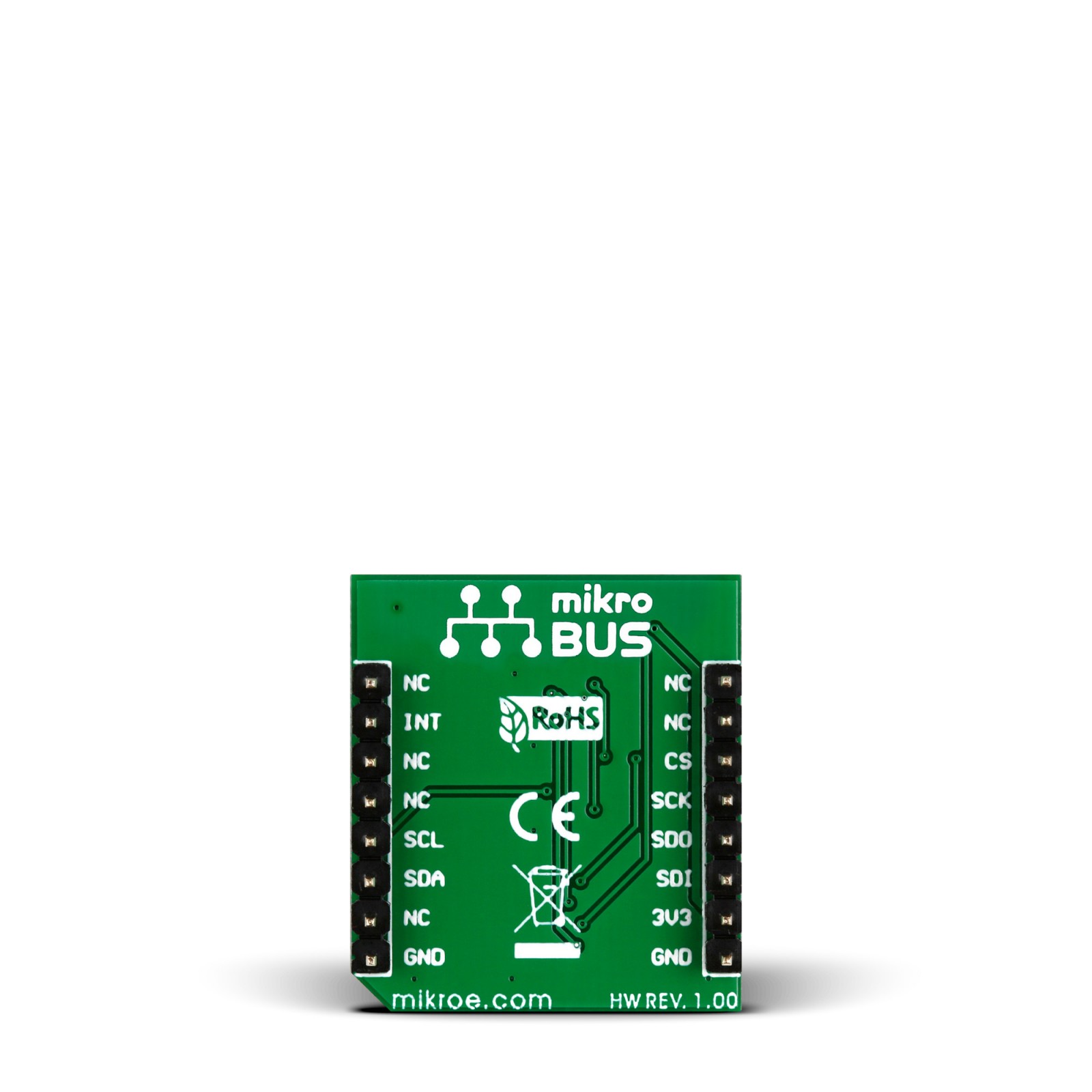
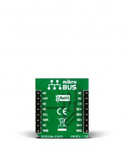
This table shows how the pinout on Accel 3 Click corresponds to the pinout on the mikroBUS™ socket (the latter shown in the two middle columns).
Onboard settings and indicators
Label | Name | Default | Description |
---|---|---|---|
– | PWR | – | Power LED Indicator |
J1A,J2A,J3A,J5A | – | Right | Communication Interface Selection SPI/I2C: Left position SPI, Right position I2C |
J4A | I2C ADDR | Left | I2C Address Selection 0/1: Left position 0, Right position 1 |
J6A | – | Right | Inertial Interrupt Selection INT2/INT1: Left position INT2, Right position INT1 |
Accel 3 Click electrical specifications
Description | Min | Typ | Max | Unit |
---|---|---|---|---|
Supply Voltage | – | 3.3 | – | V |
Acceleration Range | ±100 | – | ±400 | g |
Resolution | – | 16 | – | bit |
Sensitivity | 49 | – | 195 | mg/digit |
Software Support
We provide a library for the Accel 3 Click as well as a demo application (example), developed using MIKROE compilers. The demo can run on all the main MIKROE development boards.
Package can be downloaded/installed directly from NECTO Studio Package Manager (recommended), downloaded from our LibStock™ or found on Mikroe github account.
Library Description
This library contains API for Accel3 Click driver.
Key functions
-
This function select communication mode and executes start initialization.
-
This function reads Accel data ( X, Y and Z axis ) from the desired Accel registers of the H3LIS331DL module.
Example Description
This is an example which demonstrates the usage of Accel 3 Click board™.
void application_task ( void )
{
accel3_read_data( &accel3, &accel3_data );
Delay_ms ( 100 );
log_printf( &logger, " Accelerometer rn" );
log_printf( &logger, "----------------------------rn" );
log_printf( &logger, " X = %6d rn", accel3_data.x );
log_printf( &logger, " Y = %6d rn", accel3_data.y );
log_printf( &logger, " Z = %6d rn", accel3_data.z );
log_printf( &logger, "----------------------------rn" );
Delay_ms ( 1000 );
}
The full application code, and ready to use projects can be installed directly from NECTO Studio Package Manager (recommended), downloaded from our LibStock™ or found on Mikroe github account.
Other Mikroe Libraries used in the example:
- MikroSDK.Board
- MikroSDK.Log
- Click.Accel3
Additional notes and informations
Depending on the development board you are using, you may need USB UART click, USB UART 2 Click or RS232 Click to connect to your PC, for development systems with no UART to USB interface available on the board. UART terminal is available in all MIKROE compilers.
mikroSDK
This Click board™ is supported with mikroSDK – MIKROE Software Development Kit. To ensure proper operation of mikroSDK compliant Click board™ demo applications, mikroSDK should be downloaded from the LibStock and installed for the compiler you are using.
For more information about mikroSDK, visit the official page.