How does it work?
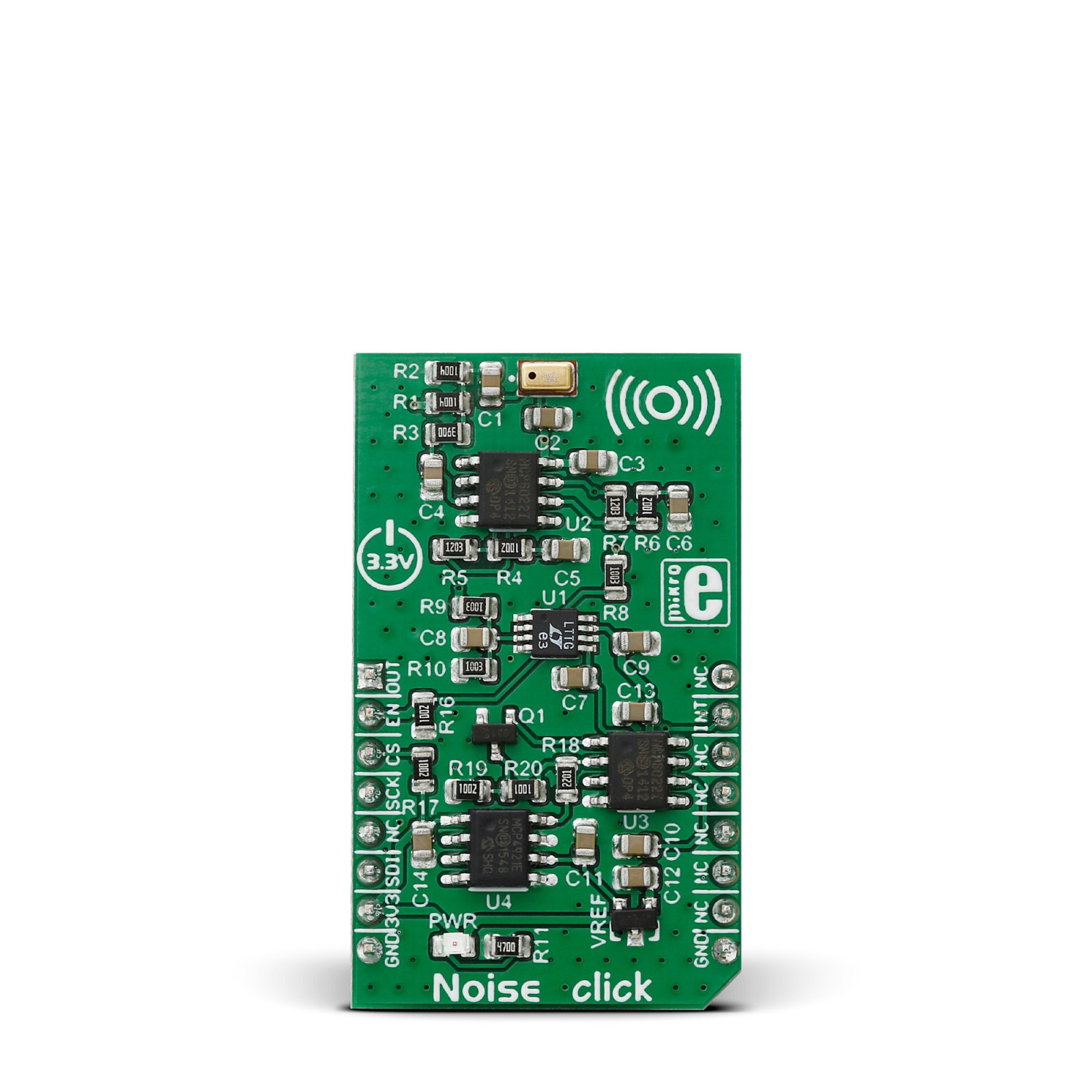
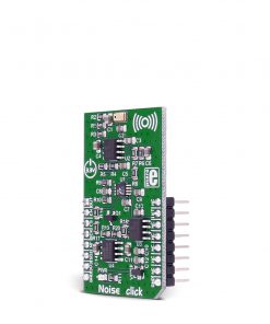
Noise Click is based on the MCP4921, a 12-bit DAC with an SPI interface from Microchip. This single-channel DAC has a rail-to-rail output, a fast-setting time and 450KHz of multiplier mode. The MCP4921 on the Noise Click sets the threshold in 12-bit resolution steps from 0 up to 4096. The noise from the environment this Click board™ receives through the MM034202-11, an analog MEMS microphone from DB Unlimited. It has omnidirectional directivity, a sensitivity of around -42dB, a signal-to-noise ratio of 59dB, and works in a frequency range from 100 up to 10000Hz.
This Click board™ also includes two MCP6022s, a rail-to-rail input/output 10MHz Op Amps from Microchip. The operational amplifiers feature wide bandwidth up to 10MHz, low noise, low input offset voltage, and low distortion. The first MCP6022 processes the microphone signal. Then, the amplified voltages pass through the LTC1966, a precision micropower ∆∑ RMS-to-DC converter from Analog Devices. This converter has constant bandwidth independent of the input voltage, flexible rail-to-rail inputs, and outputs and is more accurate than conventional log antilog similar RMS-to-DC converters. After processing with the LTC1966, the signal then goes into the second operational amplifier, which functions as a voltage comparator, from which the interrupt signal originates.
To avoid triggering the interrupt hundreds of times per second as ambient noise oscillates near the threshold, a hysteresis circuit is also employed. For that purpose, the Noise Click comes with the MAX6106, a low-cost, micropower, low-dropout, high-output-current voltage reference of 2.048V from Analog Devices.
The Noise Click uses an SPI serial interface to communicate with the host MCU over the mikroBUS™ socket. The LTC1966 RMS-to-DC converter can be disabled with the HIGH logic state on the EN pin of the mikroBUS™ socket. No matter the logic state on the enable pin, the voltage levels can still be monitored over the AN pin. When the ambient noise reaches the set threshold, the interrupt INT pin is pulled HIGH.
This Click board™ can be operated only with a 3.3V logic voltage level. The board must perform appropriate logic voltage level conversion before using MCUs with different logic levels. However, the Click board™ comes equipped with a library containing functions and an example code that can be used, as a reference, for further development.
Specifications
Type
Microphone
Applications
Can be used for the development of the application of sound monitoring for alarm systems and environmental monitoring
On-board modules
MCP4921 – 12-bit DAC with an SPI interface from Microchip
MM034202-11 – analog MEMS microphone from DB Unlimited
MCP6022 – rail-to-rail input/output 10MHz Op Amps from Microchip
LTC1966 – micropower ∆∑ RMS-to-DC converter from Analog Devices
MAX6106 – micropower, low-dropout, high-output-current voltage reference of 2.048V from Analog Devices
Key Features
Configurable threshold in steps 0 – 4096, hysteresis circuitry for stable operation, interrupt signal and direct monitor of voltage over an analog pin, a large frequency range, good sensitivity, omnidirectional directivity, and more
Interface
SPI
Feature
No ClickID
Compatibility
mikroBUS™
Click board size
M (42.9 x 25.4 mm)
Input Voltage
3.3V
Pinout diagram
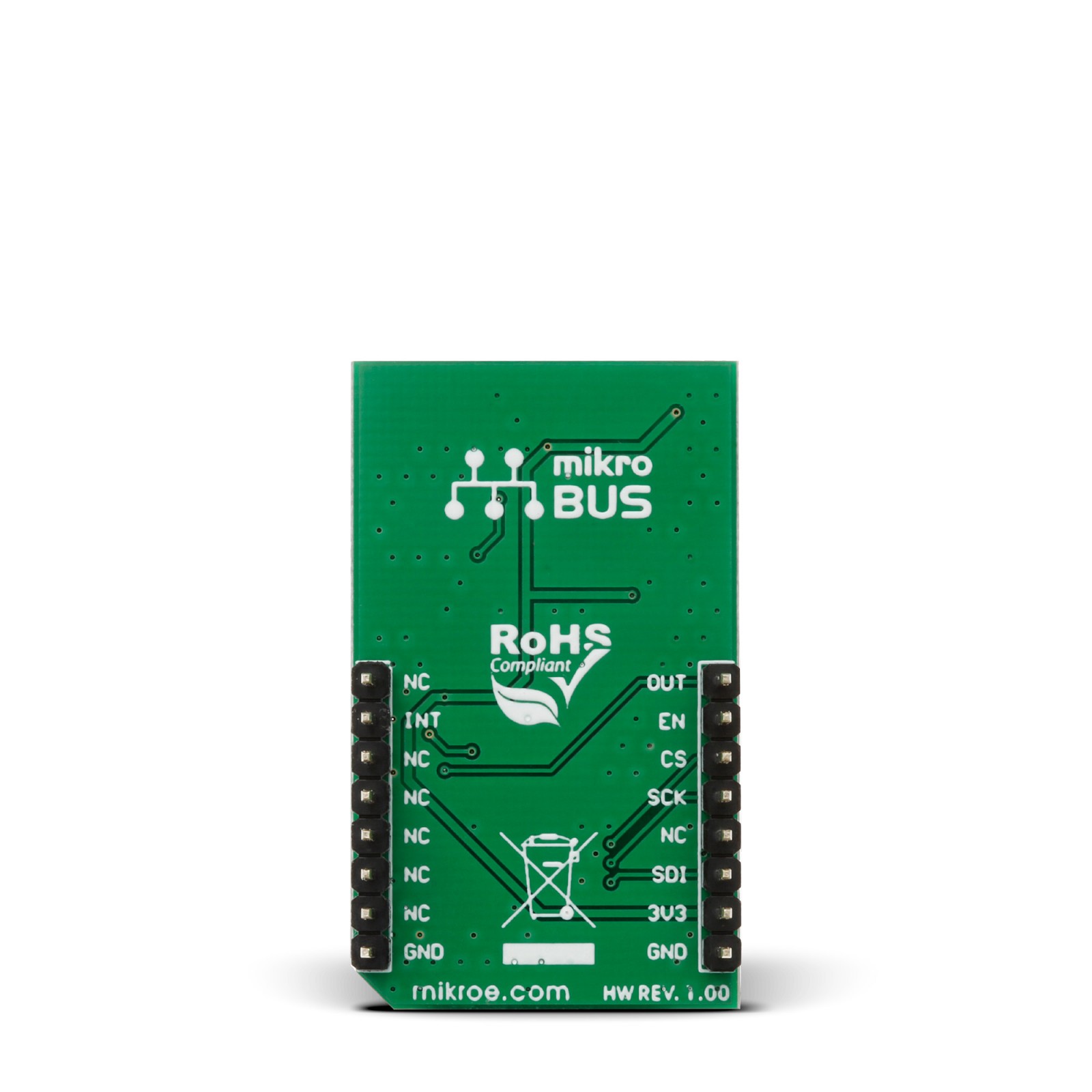
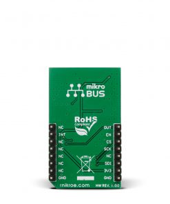
This table shows how the pinout on Noise Click corresponds to the pinout on the mikroBUS™ socket (the latter shown in the two middle columns).
Onboard settings and indicators
Label | Name | Default | Description |
---|---|---|---|
LD1 | PWR | – | Power LED Indicator |
Noise Click electrical specifications
Description | Min | Typ | Max | Unit |
---|---|---|---|---|
Supply Voltage | – | 3.3 | – | V |
Noise Frequency Range | 100 | – | 10000 | Hz |
Sensitivity | – | – | -42 | dB |
Signal to Noise Ratio | – | – | 59 | dB |
Software Support
We provide a library for the Noise Click as well as a demo application (example), developed using MIKROE compilers. The demo can run on all the main MIKROE development boards.
Package can be downloaded/installed directly from NECTO Studio Package Manager (recommended), downloaded from our LibStock™ or found on Mikroe github account.
Library Description
This library contains API for Noise Click driver.
Key functions
-
This function sets command register.
-
This function switches click on or off.
-
This function reads value from adc.
Example Description
This example performs noise monitoring and 2D graph
plotting based on measured ambient noise using Noise Click.
void application_task ( void )
{
uint8_t interrupt_status;
interrupt_status = noise_check_int_pin( &noise );
adc_value = noise_read_adc( &noise );
plot_data( adc_value );
Delay_ms( 5 );
if (interrupt_status == 1)
{
log_printf( &logger, " Sound threshold exceeded rn" );
}
}
The full application code, and ready to use projects can be installed directly from NECTO Studio Package Manager (recommended), downloaded from our LibStock™ or found on Mikroe github account.
Other Mikroe Libraries used in the example:
- MikroSDK.Board
- MikroSDK.Log
- Click.noise
Additional notes and informations
Depending on the development board you are using, you may need USB UART click, USB UART 2 Click or RS232 Click to connect to your PC, for development systems with no UART to USB interface available on the board. UART terminal is available in all MIKROE compilers.
mikroSDK
This Click board™ is supported with mikroSDK – MIKROE Software Development Kit. To ensure proper operation of mikroSDK compliant Click board™ demo applications, mikroSDK should be downloaded from the LibStock and installed for the compiler you are using.
For more information about mikroSDK, visit the official page.