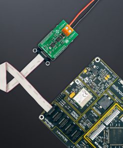
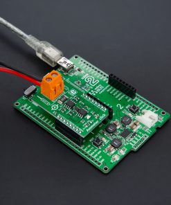
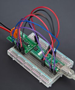
NOTE: It’s crucial to avoid powering the board from the identical source that you intend to measure.
How does it work?
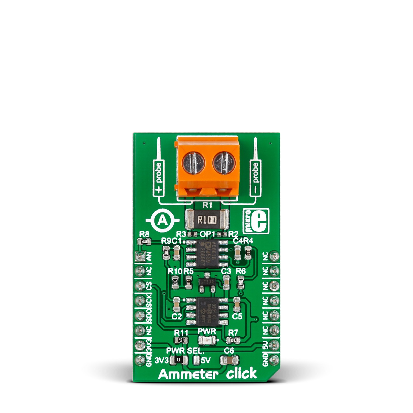
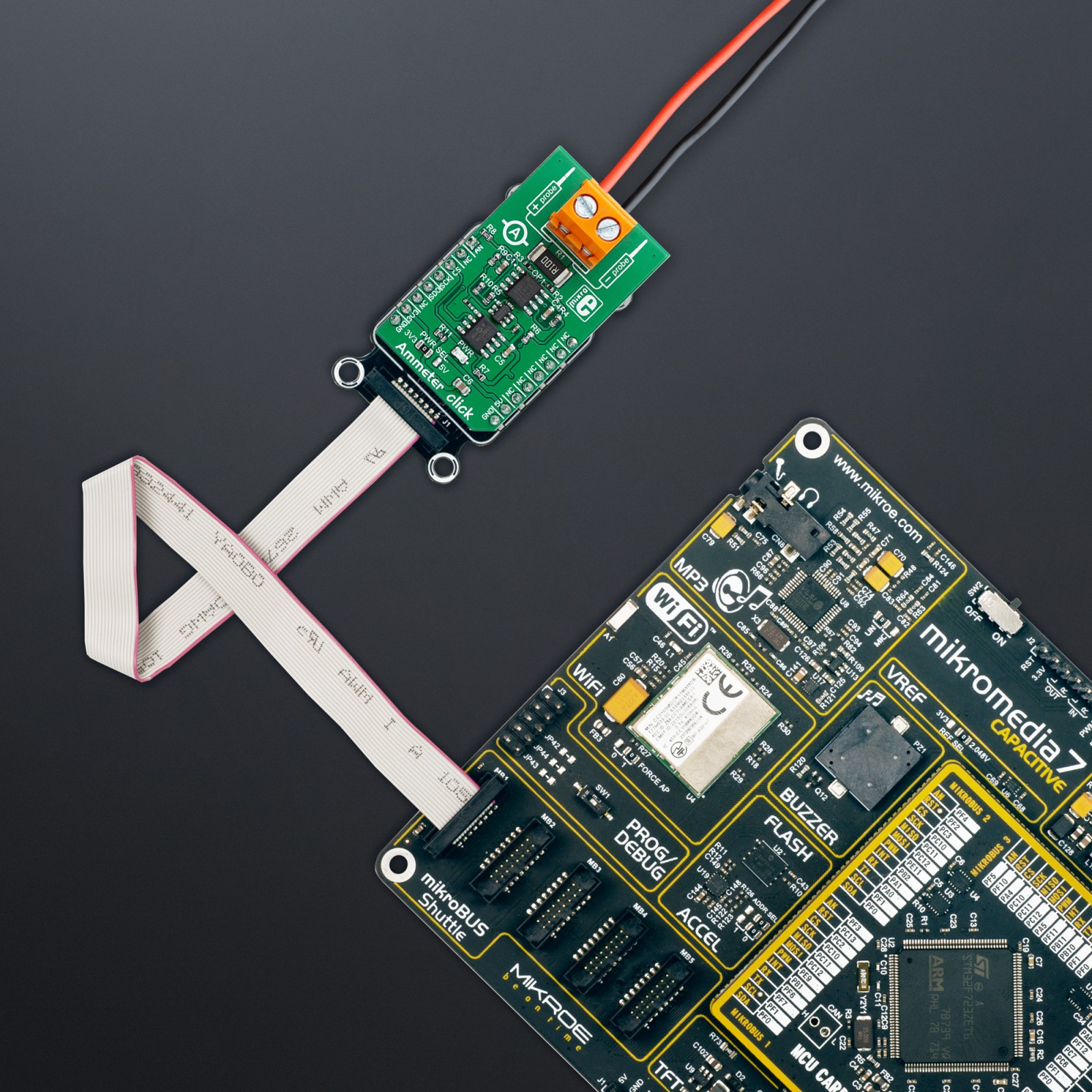
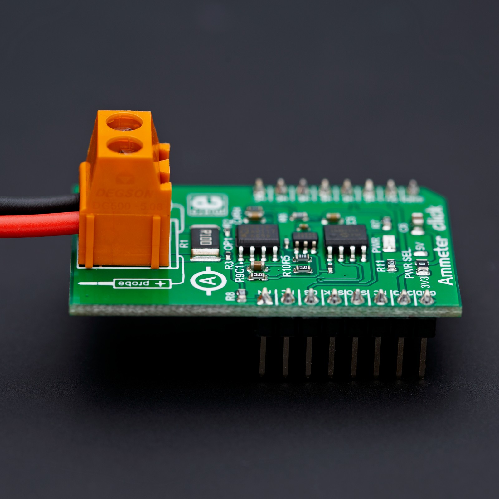
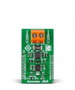
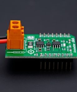
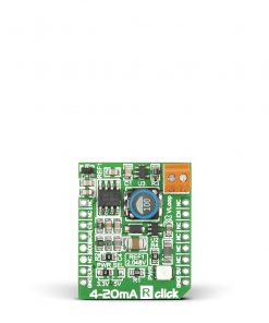
Ammeter Click is based on the AD8616, a precision 20MHz CMOS rail-to-rail input/output operational amplifier from Analog Devices. It is a dual single-supply amplifier featuring very low offset voltage, wide signal bandwidth, and low input voltage and current noise. The AD8616 uses a patented trimming technique that achieves superior precision without laser trimming. Two onboard screw terminals labeled probe+ and probe-are bringing in the current, which then passes through a shunt resistor. A voltage proportional to the strength of the current is generated across the resistor, which is then processed in the operational amplifier. The voltage amplified through the AD8616 can be directly monitored through the AN pin of the mikroBUS™ socket.
One of the main features of the Ammeter Click is the MCP3201, a 12-bit A/D converter with the SPI serial interface from Microchip. This A/D converter has a sampling rate of up to 100ksps and has an onboard sample and hold circuitry. It provides a single pseudo-differential input with maximum differential nonlinearity at ±1LSB. The AD8616 fed the amplified current to this A/D convertor, which gets the 2.048V reference voltage from the MAX6106, a micropower low-dropout high-output-current voltage reference from Analog Devices. The MCP3201 outputs digital value through the mikroBUS™ socket SPI interface to the host MCU.
This Click board™ can operate with either 3.3V or 5V logic voltage levels selected via the PWR SEL jumper. This way, both 3.3V and 5V capable MCUs can use the communication lines properly. However, the Click board™ comes equipped with a library containing easy-to-use functions and an example code that can be used, as a reference, for further development.
Specifications
Type
Current sensor,Measurements
Applications
Can be used for the development of applications based on electric current measuring and monitoring, tools, and more
On-board modules
AD8616 – rail-to-rail input/output operational amplifier from Analog Devices
Key Features
Maximum safe voltage 48V, exact amperage between 1mA and 1A for DC, AC current by deriving the value from peak-to-peak measurements, 12-bit ADC, direct analog readings, and more
Interface
Analog,SPI
Feature
No ClickID
Compatibility
mikroBUS™
Click board size
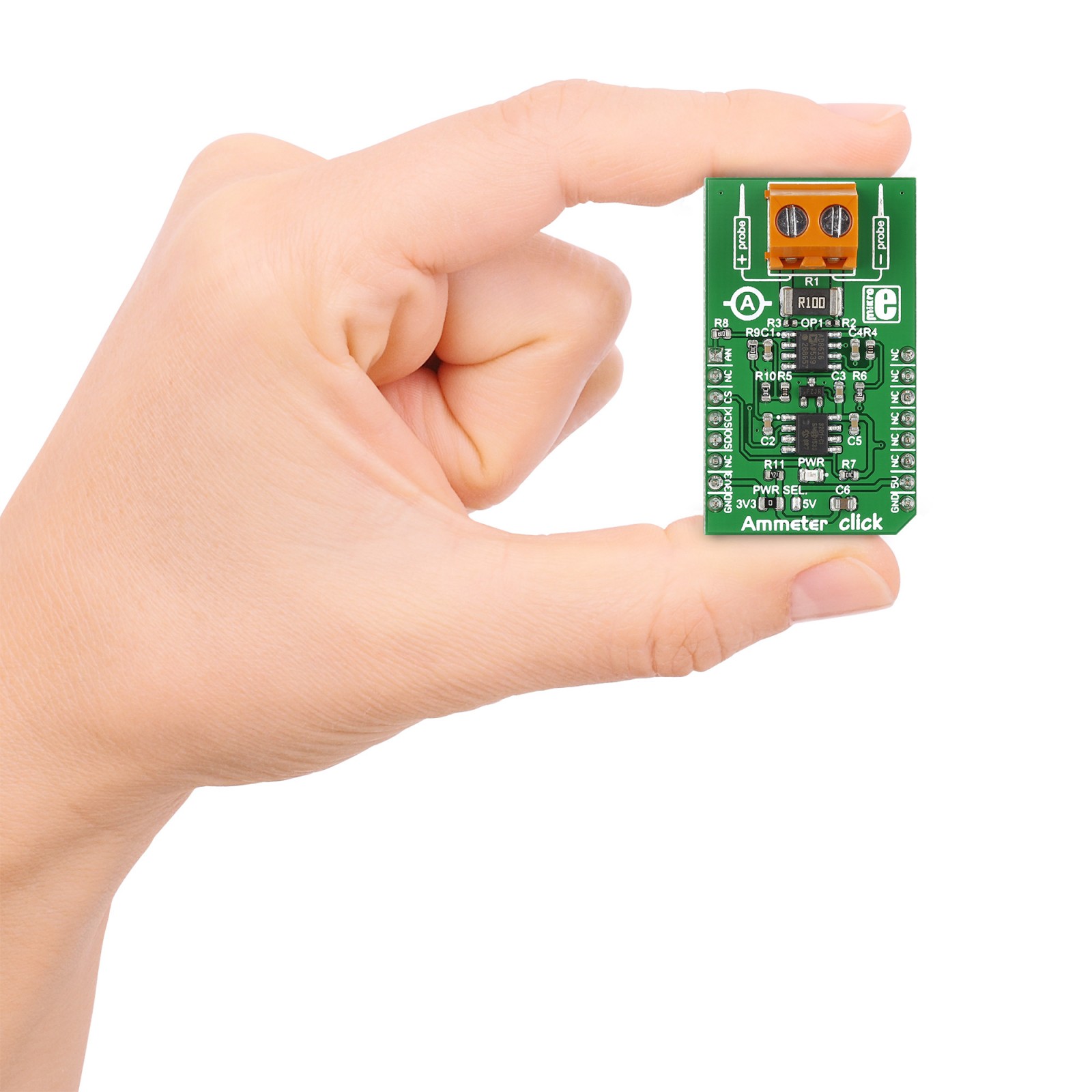
M (42.9 x 25.4 mm)
Input Voltage
3.3V or 5V
Pinout diagram
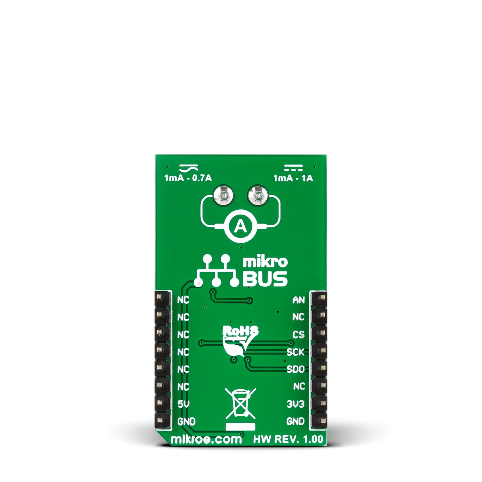
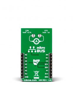
This table shows how the pinout on Ammeter Click corresponds to the pinout on the mikroBUS™ socket (the latter shown in the two middle columns).
Onboard settings and indicators
Label | Name | Default | Description |
---|---|---|---|
LD1 | PWR | – | Power LED Indicator |
JP1 | PWR SEL | Left | Power Voltage Level Selection 3V3/5V: Left position 3V3, Right position 5V |
Ammeter Click electrical specifications
Description | Min | Typ | Max | Unit |
---|---|---|---|---|
Supply Voltage | 3.3 | – | 5 | V |
Maximum Safe Voltage | – | – | 48 | V |
Amperage Range for DC | 1 | – | 1000 | mA |
Amperage Range for AC | 1 | – | 700 | mA |
Software Support
We provide a library for the Ammeter Click as well as a demo application (example), developed using MIKROE compilers. The demo can run on all the main MIKROE development boards.
Package can be downloaded/installed directly from NECTO Studio Package Manager (recommended), downloaded from our LibStock™ or found on Mikroe github account.
Library Description
This library contains API for Ammeter Click driver.
Key functions
- Function is used to measure amperage of a power consumer connected to the Click board™.
Example Description
Demo app measures and displays current by using Ammeter Click board™.
void application_task ( void )
{
amperage = ammeter_amperage( &ammeter );
log_printf( &logger, " Current: %.2f mA rn", amperage );
log_printf( &logger, "-----------------------rn" );
Delay_ms( 1000 );
}
The full application code, and ready to use projects can be installed directly from NECTO Studio Package Manager (recommended), downloaded from our LibStock™ or found on Mikroe github account.
Other Mikroe Libraries used in the example:
- MikroSDK.Board
- MikroSDK.Log
- Click.Ammeter
Additional notes and informations
Depending on the development board you are using, you may need USB UART click, USB UART 2 Click or RS232 Click to connect to your PC, for development systems with no UART to USB interface available on the board. UART terminal is available in all MIKROE compilers.
mikroSDK
This Click board™ is supported with mikroSDK – MIKROE Software Development Kit. To ensure proper operation of mikroSDK compliant Click board™ demo applications, mikroSDK should be downloaded from the LibStock and installed for the compiler you are using.
For more information about mikroSDK, visit the official page.