How does it work?
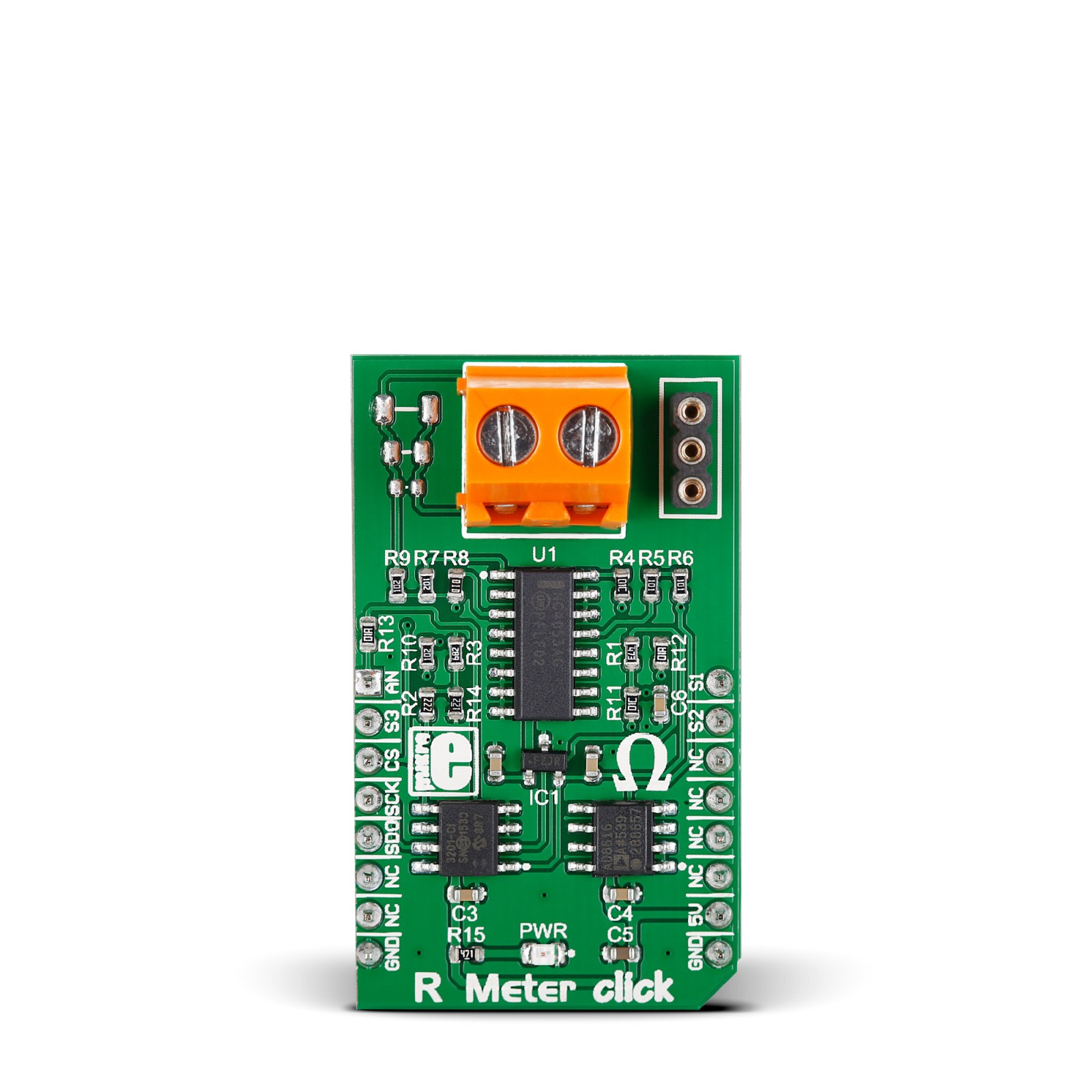
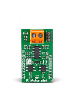
R Meter Click is based on the AD8616, a precision 20MHz CMOS rail-to-rail input/output operational amplifier from Analog Devices. This dual-channel amplifier features low offset voltage, wide signal bandwidth, and low input voltage and current noise. The analog output is fed to the MCP3201, a 12-bit AD converter with the SPI serial interface from Microchip. The MCP3201 provides a single pseudo-differential input, features on-chip sample and hold, a maximum sampling rate of up to 100ksps, and more. The MCP3201 gets the reference voltage from the MAX6106, a low-cost, micropower, low-dropout, high-output-current voltage reference from Analog Devices.
Since the AD converter has a limited min-max range of 0-2043, the R Meter Click employs the 74HC4053, a triple 2-channel analog multiplexer/demultiplexer from Nexperia. The multiplexer adjusts the input signal to the amplifier and thus allows the same ADC to measure different scopes of values (0-1K, 1K-100K, 100K-1M). The R Meter Click is a handy tool, but it’s not to be used as a precision instrument. The linearity of the OpAmp impacts the measurement.
The R Meter Click uses the 3-Wire SPI serial interface of the MCP3201 to communicate with the host MCU, with a frequency of up to 1.6MHz and supporting SPI 0 and SPI 1 modes. The voltage amplified through the AD8616 can be directly monitored through the AN pin of the mikroBUS™ socket. The supplied firmware (available on Libstock) automatically scans the ADC value and switches the multiplexer output based on the resistor place. The multiplexer interfaces directly with the host MCU through the mikroBUS™ socket over S1, S2, and S3 pins.
This Click board™ can be operated only with a 5V logic voltage level. The board must perform appropriate logic voltage level conversion before using MCUs with different logic levels. However, the Click board™ comes equipped with a library containing functions and an example code that can be used, as a reference, for further development.
Specifications
Type
Measurements
Applications
Can be used for the development of applications based on resistance measurements, tools, and more
On-board modules
AD8616 – rail-to-rail input/output operational amplifier from Analog Devices
Key Features
Resistance range from 0 up to 1M, three plates for measurement of the SMD resistors 0603, 0805, and 1206 as a standard SMD package size, a PTH socket for measurement thru-hole resistors, a screw terminal for multimeter probes, and more
Interface
Analog,GPIO,SPI
Feature
No ClickID
Compatibility
mikroBUS™
Click board size
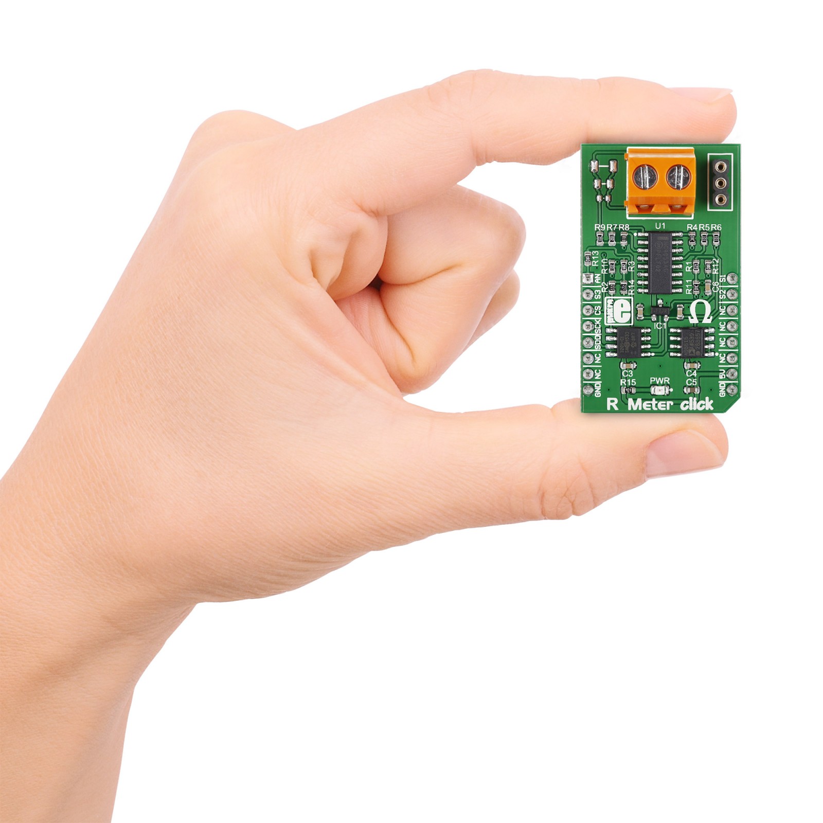
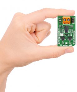
M (42.9 x 25.4 mm)
Input Voltage
5V
Pinout diagram
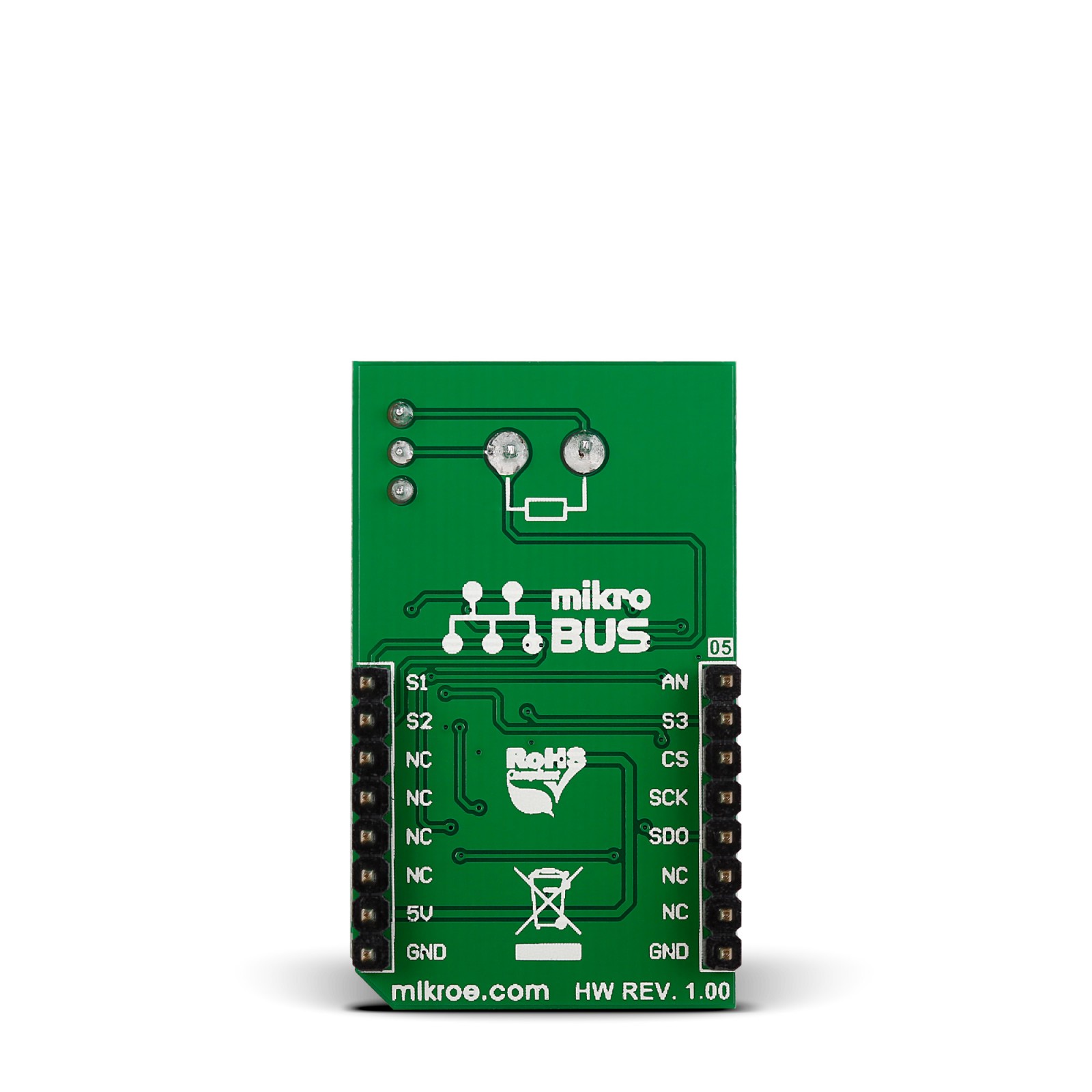
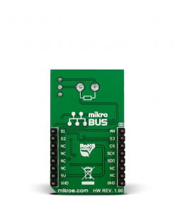
This table shows how the pinout on R Meter Click corresponds to the pinout on the mikroBUS™ socket (the latter shown in the two middle columns).
Onboard settings and indicators
Label | Name | Default | Description |
---|---|---|---|
LD1 | PWR | – | Power LED Indicator |
R Meter Click electrical specifications
Description | Min | Typ | Max | Unit |
---|---|---|---|---|
Supply Voltage | – | 5 | – | V |
Resistance Measurement Range | 0 | – | 1 | MΩ |
Maximum Sampling Rate | – | – | 100 | ksps |
Software Support
We provide a library for the R Meter Click as well as a demo application (example), developed using MIKROE compilers. The demo can run on all the main MIKROE development boards.
Package can be downloaded/installed directly from NECTO Studio Package Manager(recommended), downloaded from our LibStock™ or found on Mikroe github account.
Library Description
This library contains API for R Meter Click driver.
Key functions
-
Get resistance in OHMs function
-
Get average voltage function
-
Calculations function
Example Description
Demo app measures and displays resistance of a resistor connected to the R Meter click board.
void application_task ( void )
{
ohms = rmeter_get_ohms( &rmeter );
if ( ohms == RMETER_OVER_RANGE )
{
log_printf( &logger, " Over range! rn" );
}
else
{
log_printf( &logger, "Resistance: %.2f ohm rn", ohms );
}
log_printf( &logger, "----------------------- rn" );
Delay_ms( 1000 );
}
The full application code, and ready to use projects can be installed directly from NECTO Studio Package Manager(recommended), downloaded from our LibStock™ or found on Mikroe github account.
Other Mikroe Libraries used in the example:
- MikroSDK.Board
- MikroSDK.Log
- Click.Rmeter
Additional notes and informations
Depending on the development board you are using, you may need USB UART click, USB UART 2 Click or RS232 Click to connect to your PC, for development systems with no UART to USB interface available on the board. UART terminal is available in all MIKROE compilers.
mikroSDK
This Click board™ is supported with mikroSDK – MIKROE Software Development Kit. To ensure proper operation of mikroSDK compliant Click board™ demo applications, mikroSDK should be downloaded from the LibStock and installed for the compiler you are using.
For more information about mikroSDK, visit the official page.