Heart Rate 3 Click
R825.00 ex. VAT
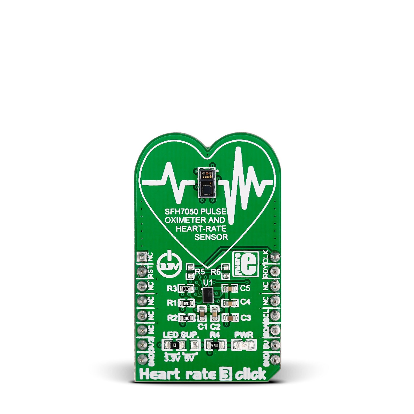
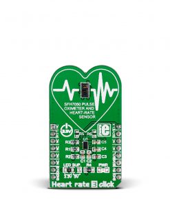
Heart Rate 3 Click is a compact add-on board that can be used for heart-rate monitoring. This board features the SFH7050, a pulse oximetry and heart rate sensor from ams OSRAM. It provides excellent readings for different usage scenarios depending on the lighting conditions or skin tones. In addition, this Click board™ features the AFE4404, an ultra-small integrated AFE for optical heart-rate monitoring and bio-sensing from Texas Instruments. This AFE4404 (analog front end) is a highly configurable chip with a transmitter and receiver, making this Click board™ a perfect solution for optical heart-rate monitoring and pulse oximetry applications.
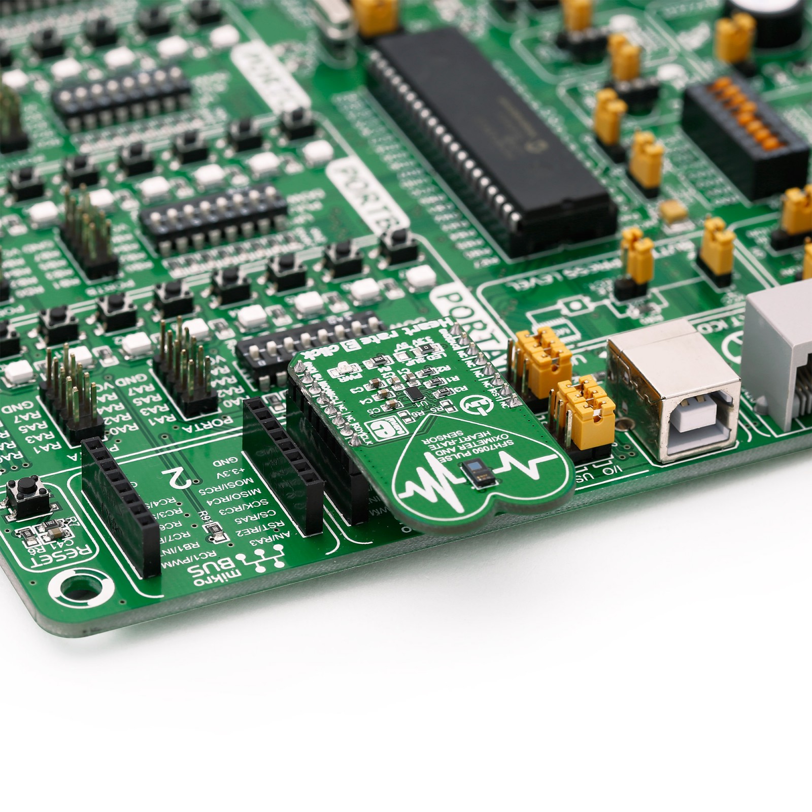
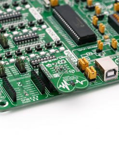
Heart Rate 3 Click is supported by a mikroSDK compliant library, which includes functions that simplify software development. This Click board™ comes as a fully tested product, ready to be used on a system equipped with the mikroBUS™ socket.
Stock: Lead-time applicable.
| 5+ | R783.75 |
| 10+ | R742.50 |
| 15+ | R701.25 |
| 20+ | R674.85 |
How does it work?
Heart Rate 3 Click is based on the SFH7050, a pulse oximetry and heart rate sensor from ams OSRAM. This multi-chip package consists of three emitters and one detector, with a light barrier to block crosstalk between the LEDs and the detector. These emitters are green, red, and infrared LEDs pointed toward the measuring objects (human skin, finger). The green LED is most commonly used to measure the dilatation of the blood vessels. The red and the infrared LED light are absorbed differently by oxygen-rich and oxygen-poor blood; therefore, the SFH7050 consists of both of them. The peak wavelength differs from each LED, but the half angle is the same for all three LEDs, ± 60°. As a detector, separated by a block barrier, the photodiode detects the intensity of light returned.
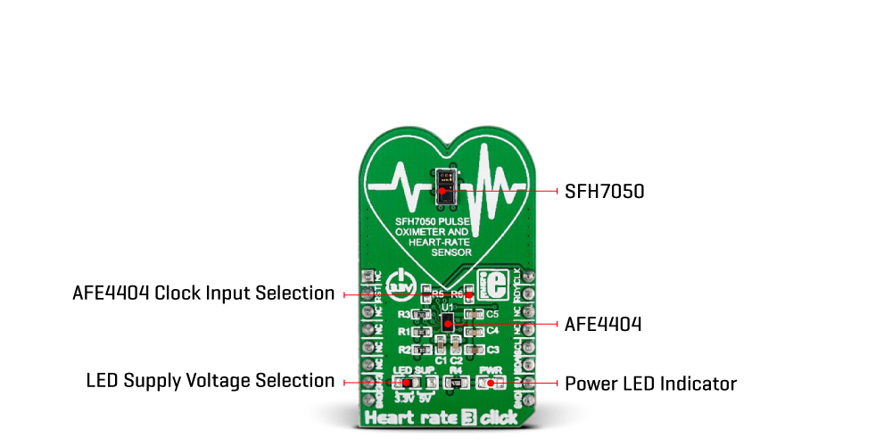
As mentioned, this Click board™ uses three LEDs and a photodiode to detect the intensity of light returned, and besides them, it also features the AFE4404, an integrated AFE for optical heart-rate monitoring and bio-sensing from Texas Instruments. The AFE4404 includes a 6-bit programmable LED current for all three LEDs, and individual DC offset subtraction DAC at TIA (Transimpedance Amplifier) input for each LED and ambient phase, allowing to increase sensor’s accuracy and remove the noise from the signal. There is also a way to average the 24-bit output from the photodiode before sending it to the BPM algorithm for better noise cancellation.
To communicate to the host MCU, the Heart Rate 3 Click uses the I2C interface of the AFE4404 over the mikroBUS™ socket. Every time all three LEDs have finished sampling and converting, the interrupt is triggered over the RDY pin, thus saving the host MCU from constantly polling the sensor for data. This pin is set to a high logic level when the PRF (a pulse repetition frequency) cycle ends, allowing four output data register to be read. The PRF can vary between 10 to 1000 samples per second.
The clock input can be selected over the CLK pin, as the AFE4404 can be clocked both internally and externally. The input clock can go up to 60MHz, but the internal divider of the IC has to be set so that the clock stays within the range from 4MHz to 6MHz. When driven by the internal clock, the device runs at 4MHz. By default, the external clock input is selected. The users can choose one of the clock options over the R5 and R6 resistors (R5 for external clock mode and R6 for internal oscillator mode). After the Power-on sequence, the AFE requires a reset. The RST pin of the mikroBUS™ socket allows the AFE to be reset by the host MCU. Pulling this pin to a low logic state for more than 200µs will put the device into the Power Down mode. The AFE can also be reset by setting a bit in the appropriate register via the I2C interface.
This Click board™ can be operated only with a 3.3V logic voltage level. The board must perform appropriate logic voltage level conversion before using MCUs with different logic levels. However, the Click board™ comes equipped with a library containing functions and an example code that can be used, as a reference, for further development. Although the Heart Rate 3 Click is a 3.3V logic level only, the onboard LED SUP jumper allows you to set the voltage for driving the SFH7050 LEDs at either 3.3V or 5V.
Specifications
Type
Biometrics,Heart Rate
Applications
Can be used for optical heart-rate monitoring and pulse oximetry applications
On-board modules
SFH7050 – pulse oximetry and heart rate sensor from ams OSRAM
AFE4404 – integrated AFE for optical heart-rate monitoring and bio-sensing from Texas Instruments
Key Features
High dynamic sensitivity, 3 integrated LED drivers with independently programmable currents, ambient light and DC offset cancellation, internal/external clock source, top-of-the-class LED and PD optical front-end, interrupt ability, and more
Interface
I2C
Feature
No ClickID
Compatibility
mikroBUS™
Click board size
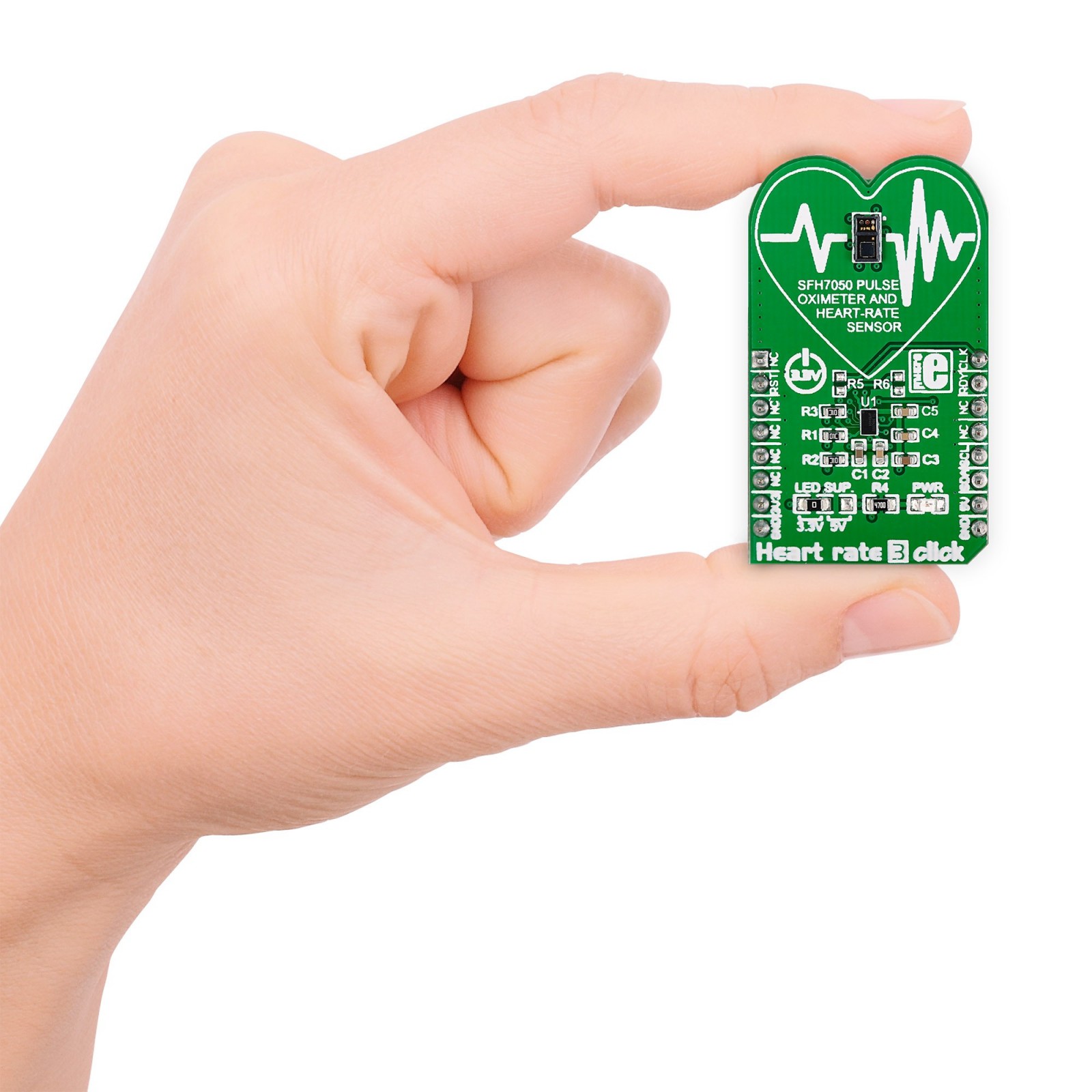
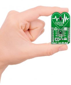
M (42.9 x 25.4 mm)
Input Voltage
3.3V or 5V
Pinout diagram
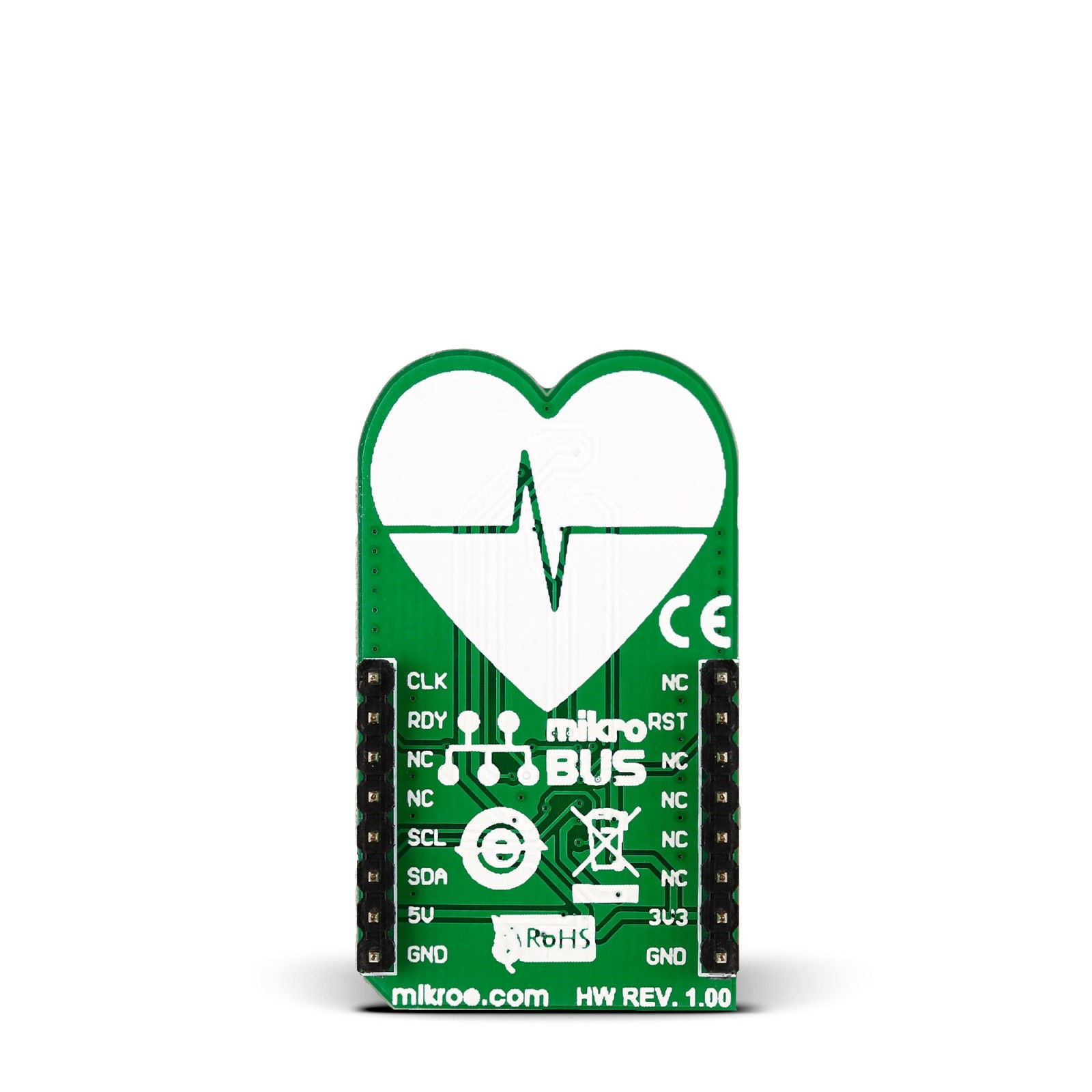
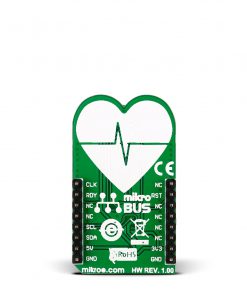
This table shows how the pinout on Heart Rate 3 Click corresponds to the pinout on the mikroBUS™ socket (the latter shown in the two middle columns).
Onboard settings and indicators
| Label | Name | Default | Description |
|---|---|---|---|
| – | PWR | – | Power LED Indicator |
| – | LED SUP | Left | LED Supply Voltage Selection 3V3/5V: Left position 3V3, Right position 5V |
| R5 | – | Unpopualted | External Clock Mode Selection |
| R6 | – | Unpopulated | Internal Clock Mode Selection |
Heart Rate 3 Click electrical specifications
| Description | Min | Typ | Max | Unit |
|---|---|---|---|---|
| Supply Voltage | 3.3 | – | 5 | V |
| IR LED Peak Emission | – | 950 | – | nm |
| Green LED Peak Emission | – | 525 | – | nm |
| Red LED Peak Emission | – | 660 | – | nm |
Software Support
We provide a library for the Heart rate 3 Click as well as a demo application (example), developed using Mikroe compilers. The demo can run on all the main Mikroe development boards.
Package can be downloaded/installed directly from NECTO Studio Package Manager (recommended), downloaded from our LibStock™ or found on Mikroe github account.
Library Description
This library contains API for Heart rate 3 Click driver.
Key functions
-
Function is used to read 32-bit value from register.
-
Function is used to set or clear rst pin.
-
Function is used to write 32-bit data into register.
Example Description
The demo application shows reflected red, green and ir values.
 void application_task ( void )
 {
     led_2 = heartrate3_read_u32( &heartrate3, HEARTRATE3_LED2VAL );
     log_printf( &logger, "LED2: %d rn", led_2 );

     aled_2 = heartrate3_read_u32( &heartrate3, HEARTRATE3_ALED2VAL );
     log_printf( &logger, "ALED2: %d rn", aled_2 );

     led_1 = heartrate3_read_u32( &heartrate3, HEARTRATE3_LED1VAL );
     log_printf( &logger, "LED1: %d rn", led_1 );

     aled_1 = heartrate3_read_u32( &heartrate3, HEARTRATE3_ALED1VAL );
     log_printf( &logger, "ALED1: %d rn", aled_1 );

     led_2_aled_2 = heartrate3_read_u32( &heartrate3, HEARTRATE3_LED2_ALED2VAL );
     log_printf( &logger, "LED2ALED2: %d rn", led_2_aled_2 );

     led_1_aled_1 = heartrate3_read_u32( &heartrate3, HEARTRATE3_LED1_ALED1VAL );
     log_printf( &logger, "LED1ALED1: %d rn", led_1_aled_1 );

     log_printf( &logger, "----------------------rn" );
     Delay_ms( 1000 );
 }
The full application code, and ready to use projects can be installed directly from NECTO Studio Package Manager (recommended), downloaded from our LibStock™ or found on Mikroe github account.
Other Mikroe Libraries used in the example:
- MikroSDK.Board
- MikroSDK.Log
- Click.HeartRate3
Additional notes and informations
Depending on the development board you are using, you may need USB UART click, USB UART 2 Click or RS232 Click to connect to your PC, for development systems with no UART to USB interface available on the board. UART terminal is available in all Mikroe compilers.
mikroSDK
This Click board™ is supported with mikroSDK – Mikroe Software Development Kit. To ensure proper operation of mikroSDK compliant Click board™ demo applications, mikroSDK should be downloaded from the LibStock and installed for the compiler you are using.
For more information about mikroSDK, visit the official page.
Resources
Downloads
| Weight | 19 g |
|---|---|
| Brand | MikroElektronika |

