How does it work?
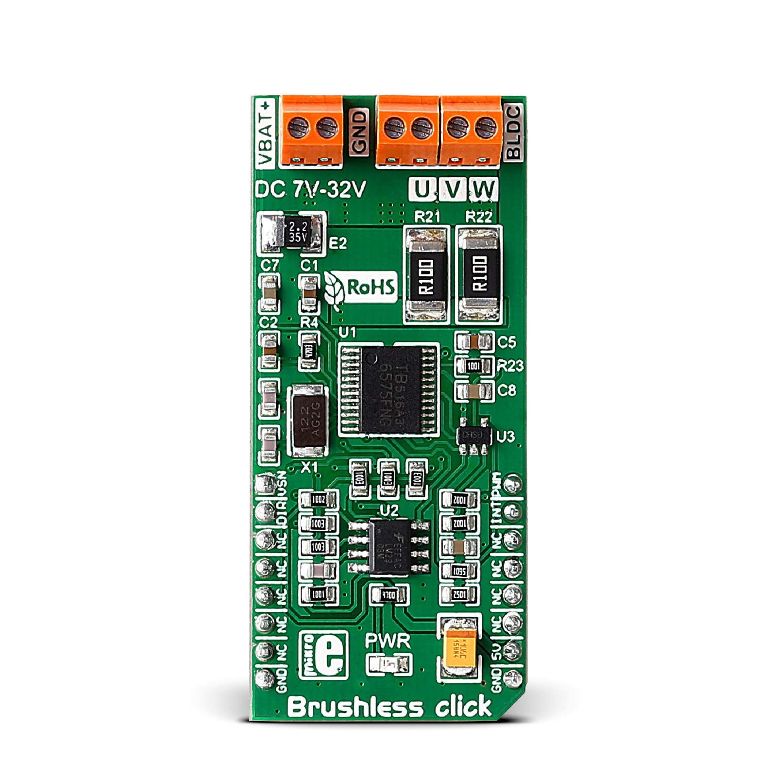
Brushless Click is based on the TB6575FNG, a PWM sensorless controller for three-phase full-wave BLDC from Toshiba Semiconductor. It is based on the PWM chopper drive. After receiving an analog voltage command input, the rotor is aligned to a known position, and then the rotation is started in a forced commutation mode, thus acquiring the back-EMF. To drive a BLDC motor in a sensorless drive, a signal is generated based on the back-EMF sensing as a natural commutation PWM signal. This natural commutation PWM is automatically switched from the forced Commutation PWM signal when a polarity signal of each phase voltage (including the back-EMF) is applied to the position signal input.
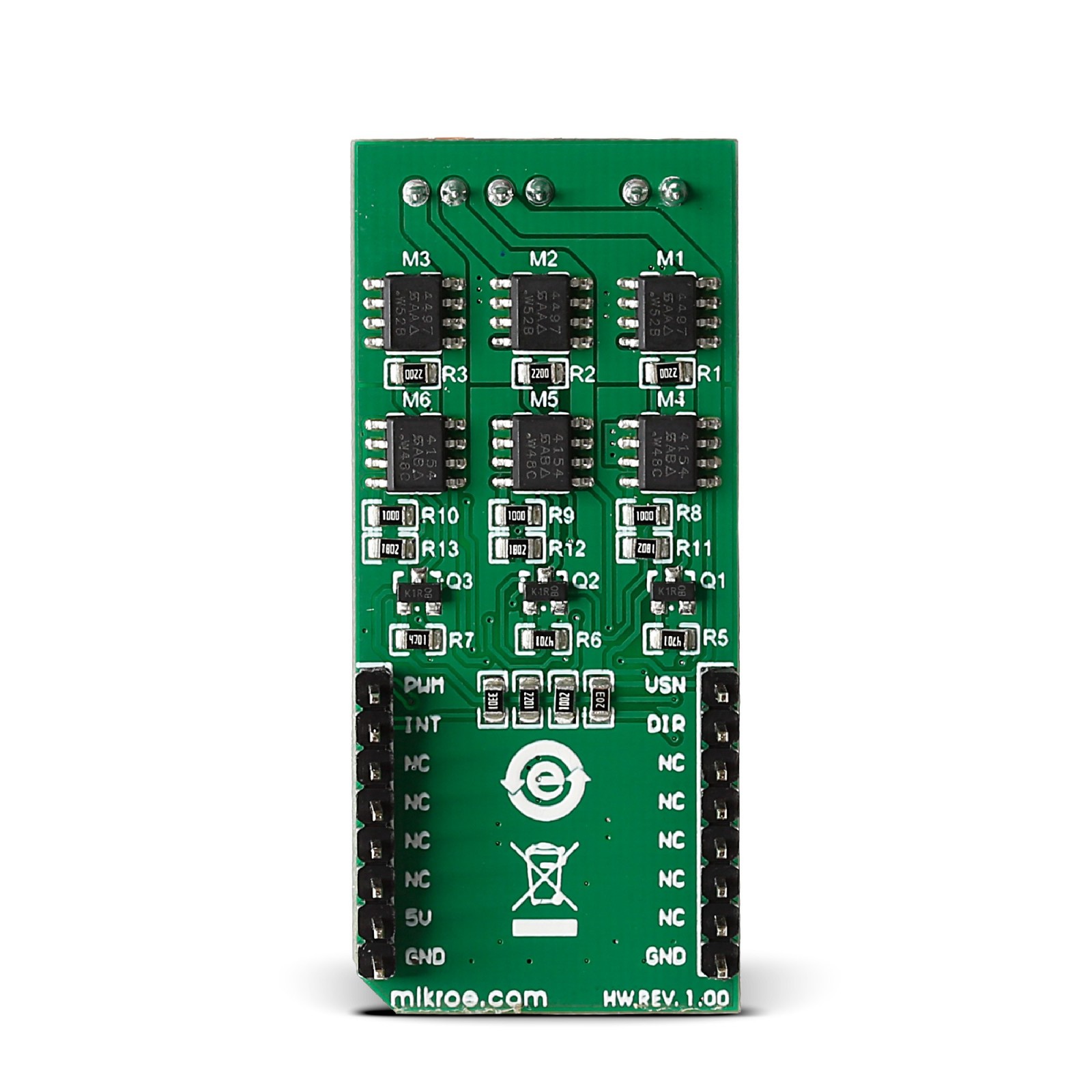
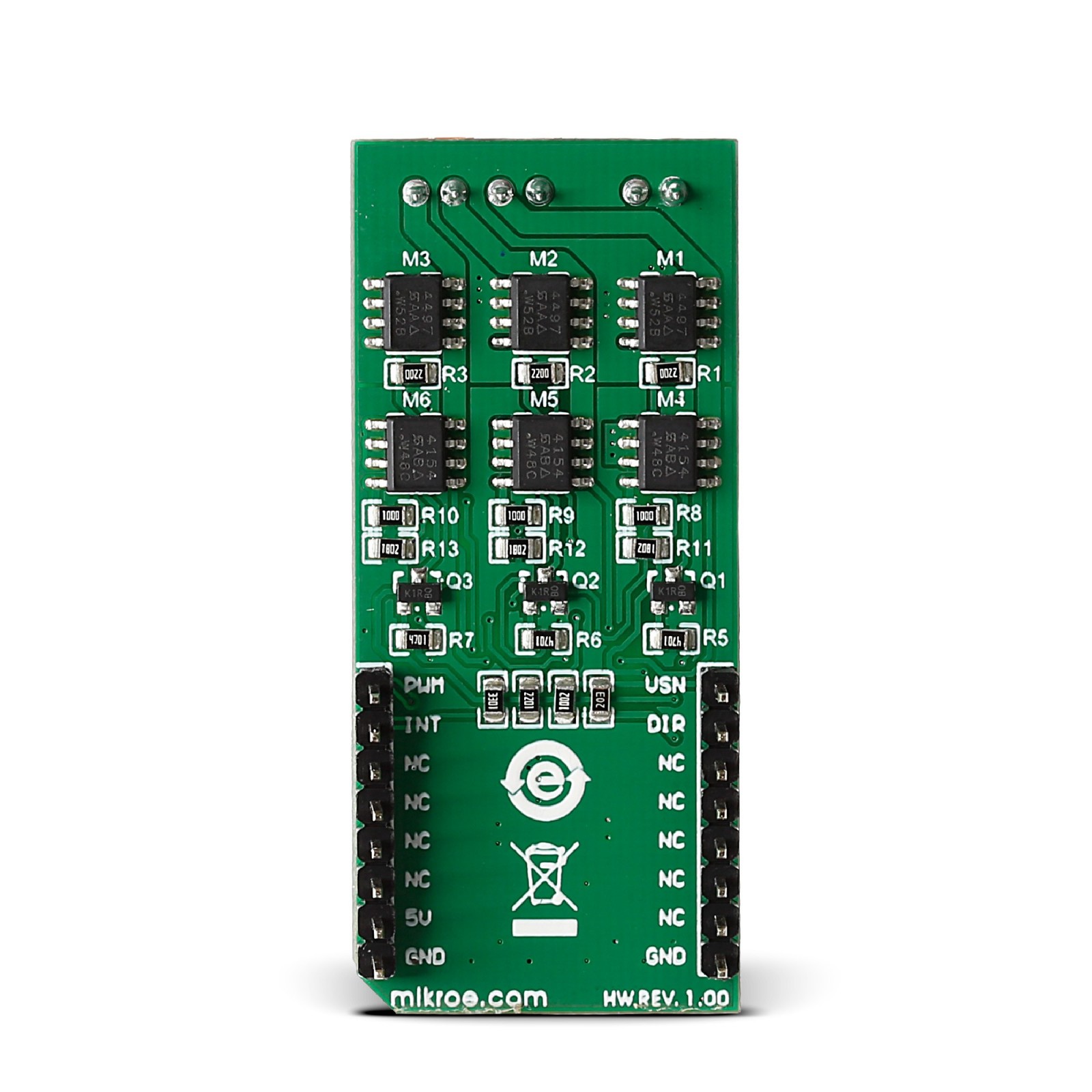
Two types of MOSFET chips onboard switch the output ON and OFF. This controls the voltage levels applied to the motor, which determines the motor shaft’s speed and rotation. These are the Si4497, a P-channel 30V MOSFET, and the Si4154, an N-channel 40V MOSFET from Vishay. Brushless click is theoretically capable of outputting higher currents; however, in such a case, the MOSFET chips have to be cooled down with an external cooler. To connect an external DC power supply, there is a VBAT screw terminal. The screw terminal labeled BLDC (GND, U, V, W) is for connecting phases of an external motor.
As a position sensing input of the TB6575FNG, this Click board™ uses the LM2903, a low-power dual voltage comparator from STMicroelectronics. For sensing purposes, this comparator uses voltages of all motor driver outputs. For a duty cycle control input, this Click board™ uses the MCP6281, a rail-to-rail operational amplifier from Microchip. This OpAmp as input uses a PWM signal from the mikroBUS™ socket.
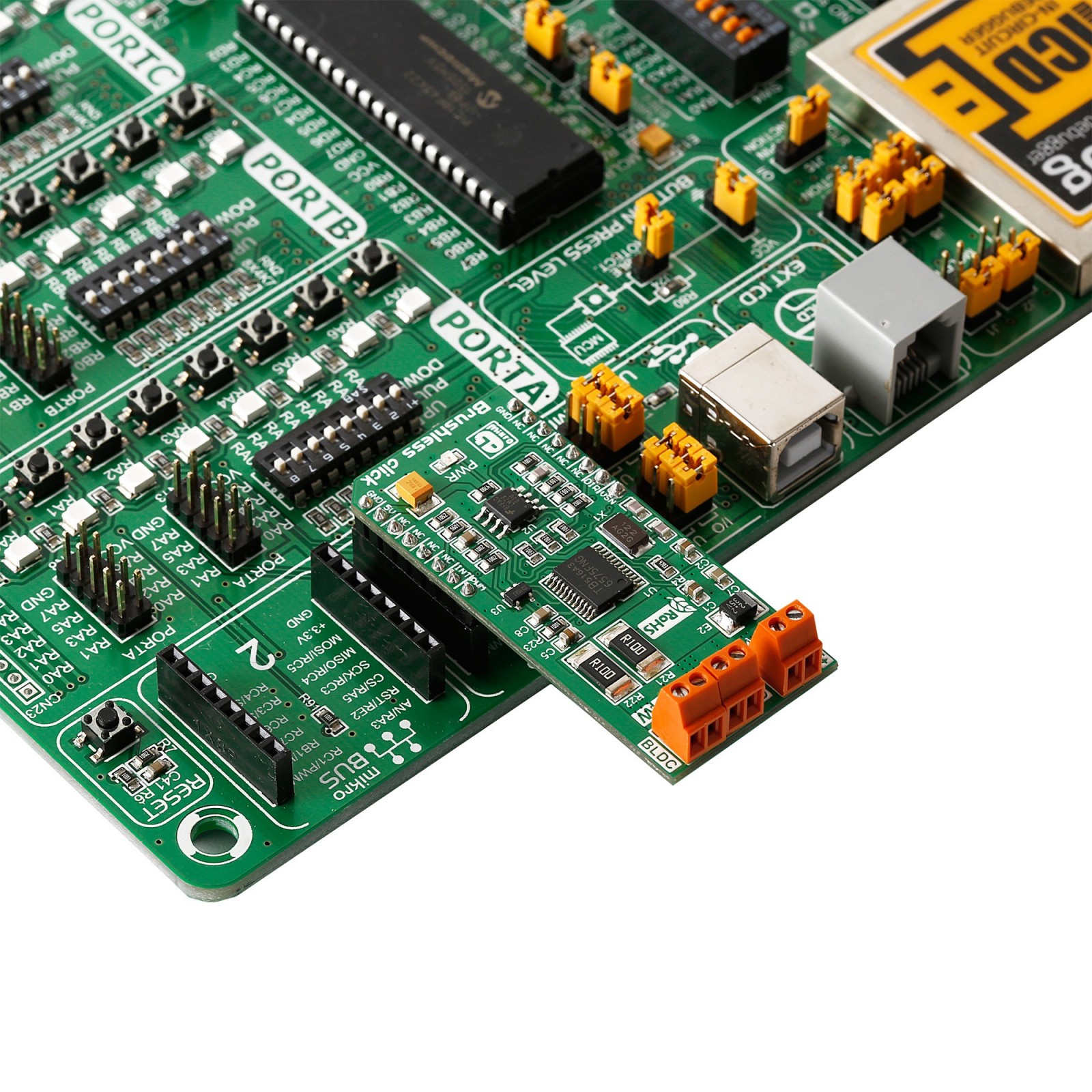
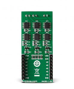
Brushless Click uses only a PWM signal as a connection with the host MCU over the mikroBUS™ socket. The signal is supplied to the WAVE position sensing input of the motor driver through the operational amplifier. The rotation speed sensing output is monitored over the INT pin of the mikroBUS™ socket. To set the rotation direction, you can use logic HIGH and LOW states on the DIR pin, HIGH for reverse, and LOW for forward rotation. The VSN pin over the resistor divider can monitor the battery voltage.
Position detection is synchronized with the PWM signal generated in the IC. A position detection error relative to the PWM frequency may occur when the IC is used in a high-speed motor. The detection is performed on the falling edge of the PWM signal. An error is recognized when the pin voltage exceeds the reference voltage.
This Click board™ can only be operated with a 5V logic voltage level. The board must perform appropriate logic voltage level conversion before using MCUs with different logic levels. However, the Click board™ comes equipped with a library containing functions and an example code that can be used, as a reference, for further development.
Specifications
Type
Brushless
Applications
Can be used for the development of driving three-phase brushless DC motors up to 2A output current rating
On-board modules
TB6575FNG – PWM sensorless controller for three-phase full-wave BLDC from Toshiba Semiconductor
Key Features
MOSFET chips toggle the output on and off, external BLDC motor up to 32V/2A, operational amplifier to prevent phase reversal, motor position detection error, overcurrent protection, direction control, speed control, lead angle control, overlap commutation, battery voltage level sensing, and more
Interface
GPIO,PWM
Feature
No ClickID
Compatibility
mikroBUS™
Click board size
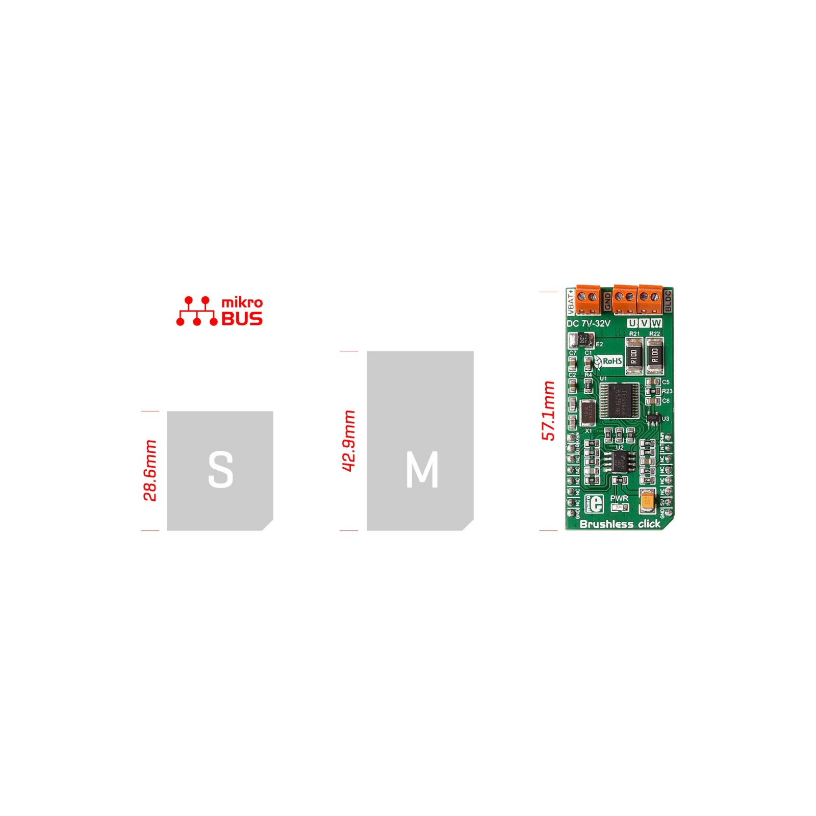
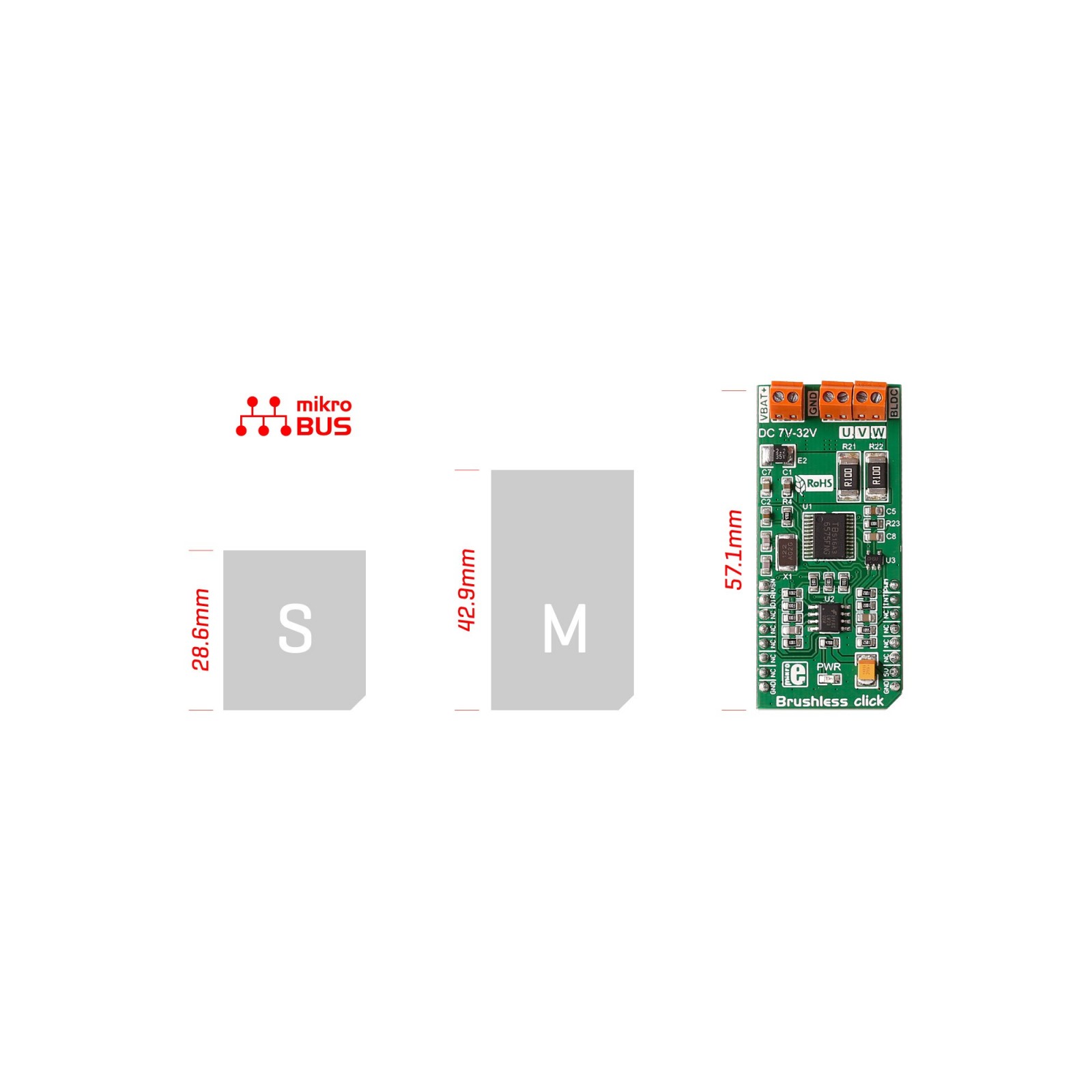
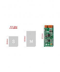
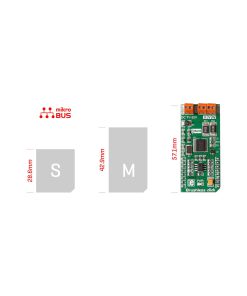
L (57.15 x 25.4 mm)
Input Voltage
5V
Pinout diagram
This table shows how the pinout on Brushless Click corresponds to the pinout on the mikroBUS™ socket (the latter shown in the two middle columns).
Onboard settings and indicators
Label | Name | Default | Description |
---|---|---|---|
LD1 | PWR | – | Power LED Indicator |
Brushless Click electrical specifications
Description | Min | Typ | Max | Unit |
---|---|---|---|---|
Supply Voltage | – | 5 | – | V |
External Voltage Range | 7 | – | 32 | V |
Maximum Output Current | – | – | 2 | A |
Software Support
We provide a library for the Brushless Click as well as a demo application (example), developed using MIKROE compilers. The demo can run on all the main MIKROE development boards.
Package can be downloaded/installed directly from NECTO Studio Package Manager (recommended), downloaded from our LibStock™ or found on Mikroe github account.
Library Description
This library contains API for Brushless Click driver.
Key functions
-
This function sets the spin direction of the motor to clockwise.
-
This function sets the spin direction of the motor to counter clockwise.
-
This function reads the digital input of the INT pin.
Example Description
This example showcases how to initialize and use the Brushless click. The click has a bru- shless motor driver which controls the work of the motor through the BLDC terminal. In order for this example to work a motor and a power supply are needed.
void application_task ( )
{
clockwise( );
counter_clockwise( );
}
The full application code, and ready to use projects can be installed directly from NECTO Studio Package Manager (recommended), downloaded from our LibStock™ or found on Mikroe github account.
Other Mikroe Libraries used in the example:
- MikroSDK.Board
- MikroSDK.Log
- Click.Brushless
Additional notes and informations
Depending on the development board you are using, you may need USB UART click, USB UART 2 Click or RS232 Click to connect to your PC, for development systems with no UART to USB interface available on the board. UART terminal is available in all MIKROE compilers.
mikroSDK
This Click board™ is supported with mikroSDK – MIKROE Software Development Kit. To ensure proper operation of mikroSDK compliant Click board™ demo applications, mikroSDK should be downloaded from the LibStock and installed for the compiler you are using.
For more information about mikroSDK, visit the official page.