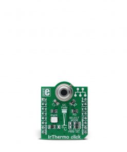
ATA663211 Click
R420.00 ex. VAT
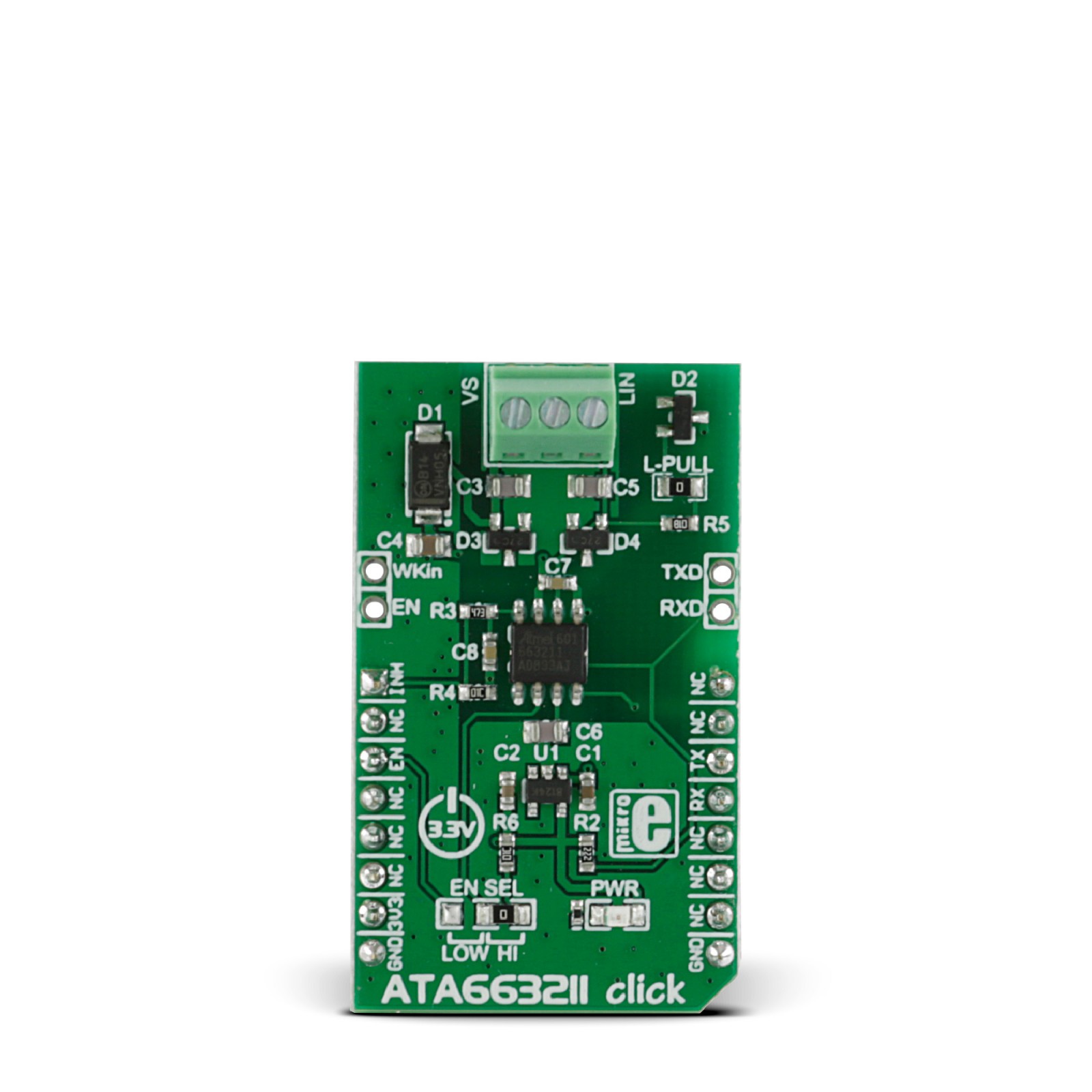
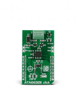
ATA663211 Click is a compact add-on board with a physical interface to automotive and industrial LIN systems. This board features the ATA663211, a fully integrated LIN transceiver from Microchip, which complies with the LIN specifications 2.0, 2.1, 2.2, 2.2A, and SAEJ2602-2. The LIN transceiver interfaces both the LIN protocol handler and the physical layer and ensures data communication up to 20Kbaud. This Click board™ makes the perfect solution for the development of automotive applications: body controllers and gateway modules, switch panels, wiper or window lift modules, door and seat control modules, and engine management units.
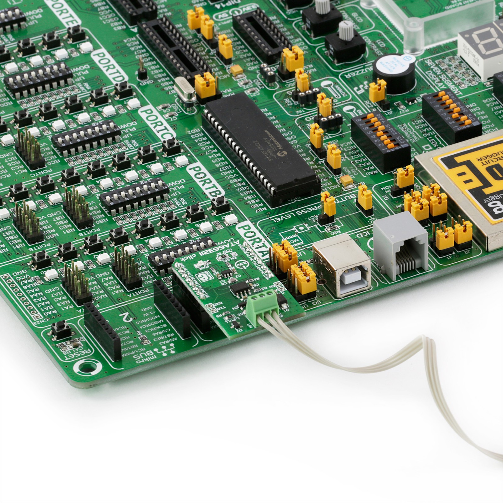
ATA663211 Click is supported by a mikroSDK compliant library, which includes functions that simplify software development. This Click board™ comes as a fully tested product, ready to be used on a system equipped with the mikroBUS™ socket.
Stock: Lead-time applicable.
| 5+ | R399.00 |
| 10+ | R378.00 |
| 15+ | R357.00 |
| 20+ | R343.56 |
How does it work?
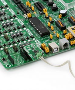
ATA663211 Click is based on the ATA663211, a LIN transceiver from Microchip. It features several protection functionalities such as over-temperature, short-circuit protection vs GND and battery, advanced EMC and ESD, and more. The integrated 3.3V onboard LDO voltage regulator is the MCP1804, an LDO regulator with shutdown from Microchip. The combination of a voltage regulator and a bus transceiver makes it possible to develop simple but powerful slave nodes in LIN bus systems. This way, ATA663211 Click can be used as a standalone LIN transceiver without being connected to a mikroBUS™ socket. An onboard LDO (low-dropout regulator) lets it supply power through the VS line screw terminal. This regulated voltage is also available on the +3.3V rail of the mikroBUS™ socket to power up the 3.3V attached host MCU.
There are several operating modes for the ATA663211 Click. In Normal mode, the LIN interface is transmitting and receiving. In Sleep mode, the transmission path is disabled, and the LIN transceiver is in low-power mode. The Failsafe mode is automatically switched at system power-up or after a wake-up event. The LIN transceiver is switched off in this mode, and the inhibit output pin is switched on. For the typical application as a Master node, the ATA663211 requires the LBUS line of the chip to be connected to the VBB of the LIN BUS, achievable via a populated L-PULL jumper. This jumper can be removed in other scenarios, such as the LIN Slave node.
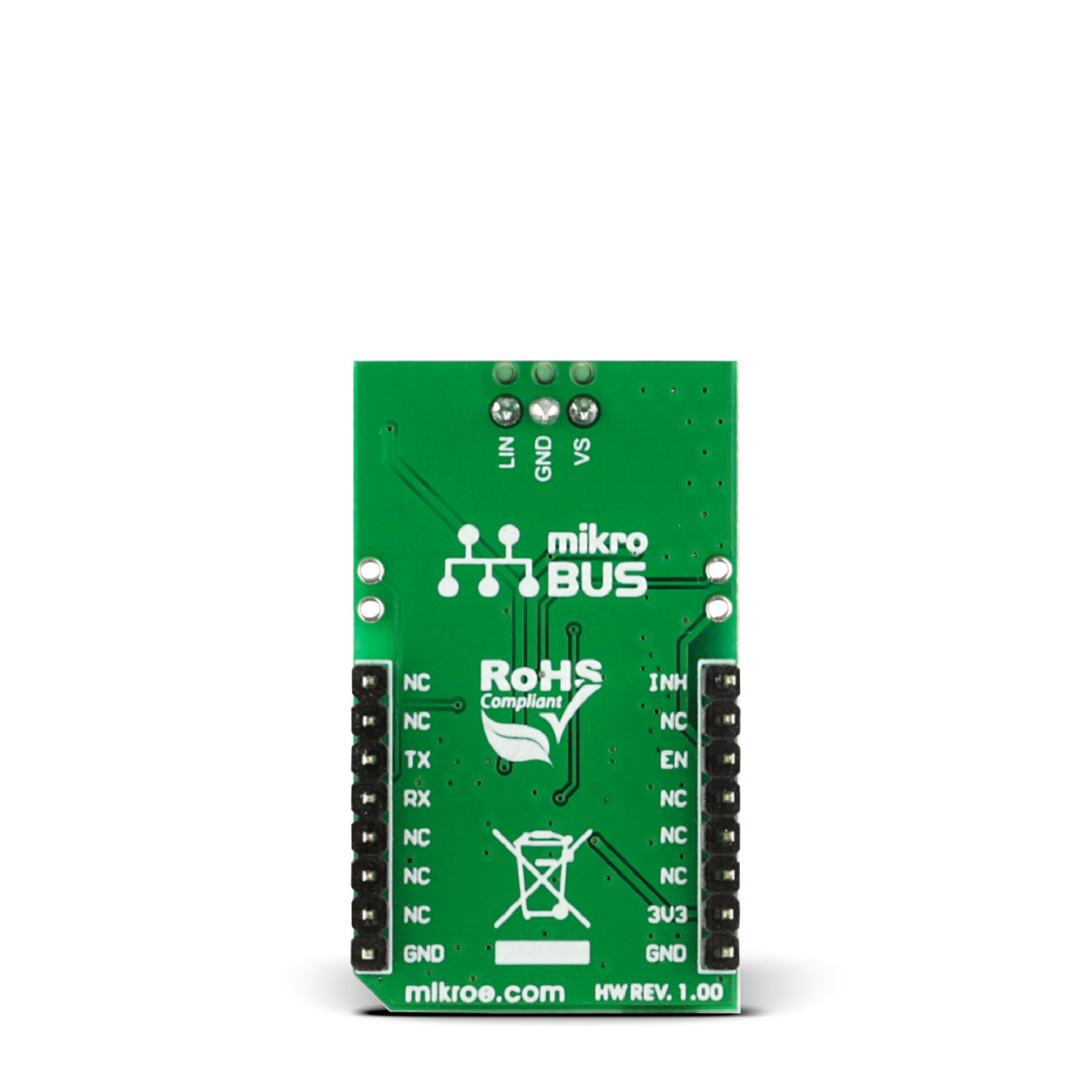
The ATA663211 communicates with the MCU using the UART RX and TX signals. Besides communication, these pins also serve to signal the failsafe condition. The undervoltage on the LIN connector can cause the failsafe condition: less than 3.9V will cause the undervoltage condition, signaled by the LOW logic state on the RX pin and the HIGH logic state on the TX pin. A LIN wake-up event from either silent or sleep mode is signaled by the LOW logic state on both the RX and TX pins. This event is being received via the LIN bus and is used to switch the ATA663211 click to an active state. On the other hand, Low on TX and HIGH on RX will signal the local wake-up. RX and TX signals are also routed to the header on the edge of the Click board™ so they can be used independently of the mikroBUS™ socket.
The inhibit output pin of the LIN transceiver is used to control the Shutdown input of the MCP1804 LDO; thus, the supply pin of the LIN transceiver itself, as the LDO, supplies the LIN transceivers supply pin with LIN operating voltage. The voltages on this line can be monitored over the INH pin of the mikroBUS™ socket via the resistor divider. To enable the LIN transceiver, there is an EN SEL jumper set to the HI position by default, thus enabling the transceiver. Setting it to the LOW position allows you to control the enable function over the EN pin of the mikroBUS™ socket. In addition, this same pin is routed to the second pair of headers to enable the LIN transceiver externally. The other pin on this header is WKin, a high-voltage input used for waking up the device.
This Click board™ can be operated only with a 3.3V logic voltage level. The board must perform appropriate logic voltage level conversion before using MCUs with different logic levels. However, the Click board™ comes equipped with a library containing functions and an example code that can be used, as a reference, for further development.
Specifications
Type
LIN
Applications
Automotive industry and other electrically harsh environments
On-board modules
Atmel LIN transceiver IC
Key Features
Data communication up to 20Kbaud, Power consumption 9μA in sleep mode, Bus pin is over-temperature and short-circuit protected
Interface
GPIO,UART
Feature
No ClickID
Compatibility
mikroBUS™
Click board size
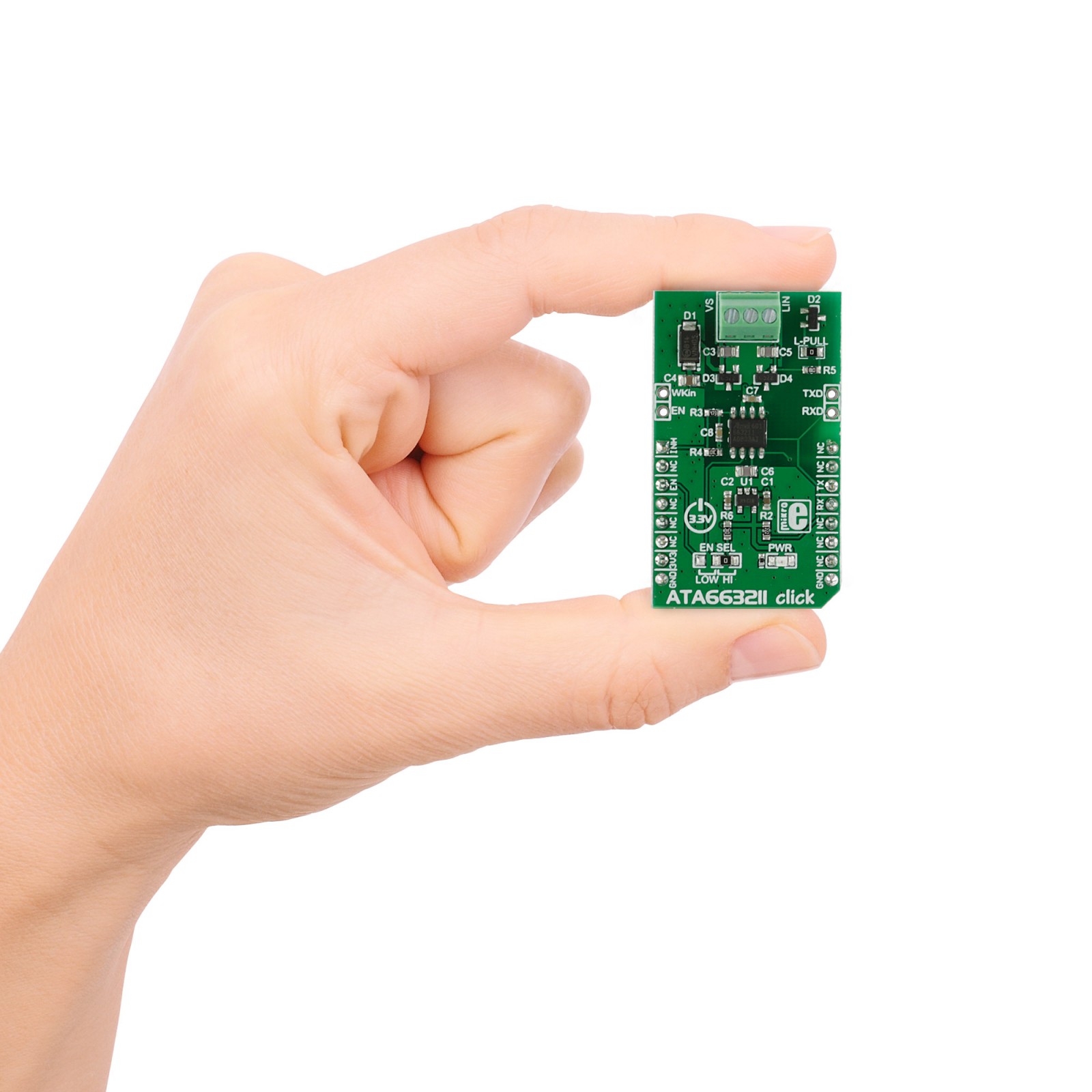
M (42.9 x 25.4 mm)
Input Voltage
3.3V
Pinout diagram
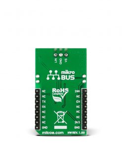
This table shows how the pinout on ATA663211 Click corresponds to the pinout on the mikroBUS™ socket (the latter shown in the two middle columns).
Onboard settings and indicators
| Label | Name | Default | Description |
|---|---|---|---|
| LD1 | PWR | – | Power LED Indicator |
| JP1 | EN SEL | Right | Chip Enable Selection LOW/HI: Left position LOW, Right position HI |
| JMPR | L-PULL | Populated | LIN Master Node Operation Selection Jumper |
ATA663211 Click electrical specifications
| Description | Min | Typ | Max | Unit |
|---|---|---|---|---|
| Supply Voltage | – | 3.3 | – | V |
| LIN Operating Voltage | 5 | 13.5 | 28 | V |
| VS Operating Voltage | – | – | 40 | V |
| Operating Current | – | 250 | – | μA |
| Data Rates with LIN-compatible Driver | – | – | 20 | Kbaud |
Software Support
We provide a library for the ATA663211 Click as well as a demo application (example), developed using MIKROE compilers. The demo can run on all the main MIKROE development boards.
Package can be downloaded/installed directly from NECTO Studio Package Manager (recommended), downloaded from our LibStock™ or found on Mikroe github account.
Library Description
This library contains API for ATA663211 Click driver.
Key functions
-
Wake-up device function.
-
Sleep mode function.
-
Check inhibit pin state function.
Example Description
This application is for handling low-speed data communication in vehicles and in industrial.
 void application_task ( void )
 {
     ata663211_data_t tmp;

     //  Task implementation.

 #ifdef DEMO_APP_RECEIVER

        // RECEIVER - UART polling

        tmp =  ata663211_generic_single_read( &ata663211 );
        log_printf( &logger, &tmp, LOG_FORMAT_BYTE );
 #endif
 #ifdef DEMO_APP_TRANSMITER

        // TRANSMITER - TX each 2 sec

        ata663211_generic_multi_write( &ata663211, demo_message, 9 );
        Delay_ms( 2000 );
 #endif
 }
The full application code, and ready to use projects can be installed directly from NECTO Studio Package Manager (recommended), downloaded from our LibStock™ or found on Mikroe github account.
Other Mikroe Libraries used in the example:
- MikroSDK.Board
- MikroSDK.Log
- Click.Ata663211
Additional notes and informations
Depending on the development board you are using, you may need USB UART click, USB UART 2 Click or RS232 Click to connect to your PC, for development systems with no UART to USB interface available on the board. UART terminal is available in all MIKROE compilers.
mikroSDK
This Click board™ is supported with mikroSDK – MIKROE Software Development Kit. To ensure proper operation of mikroSDK compliant Click board™ demo applications, mikroSDK should be downloaded from the LibStock and installed for the compiler you are using.
For more information about mikroSDK, visit the official page.
Resources
Downloads
| Weight | 30 g |
|---|---|
| Brand | MikroElektronika |

