How does it work?
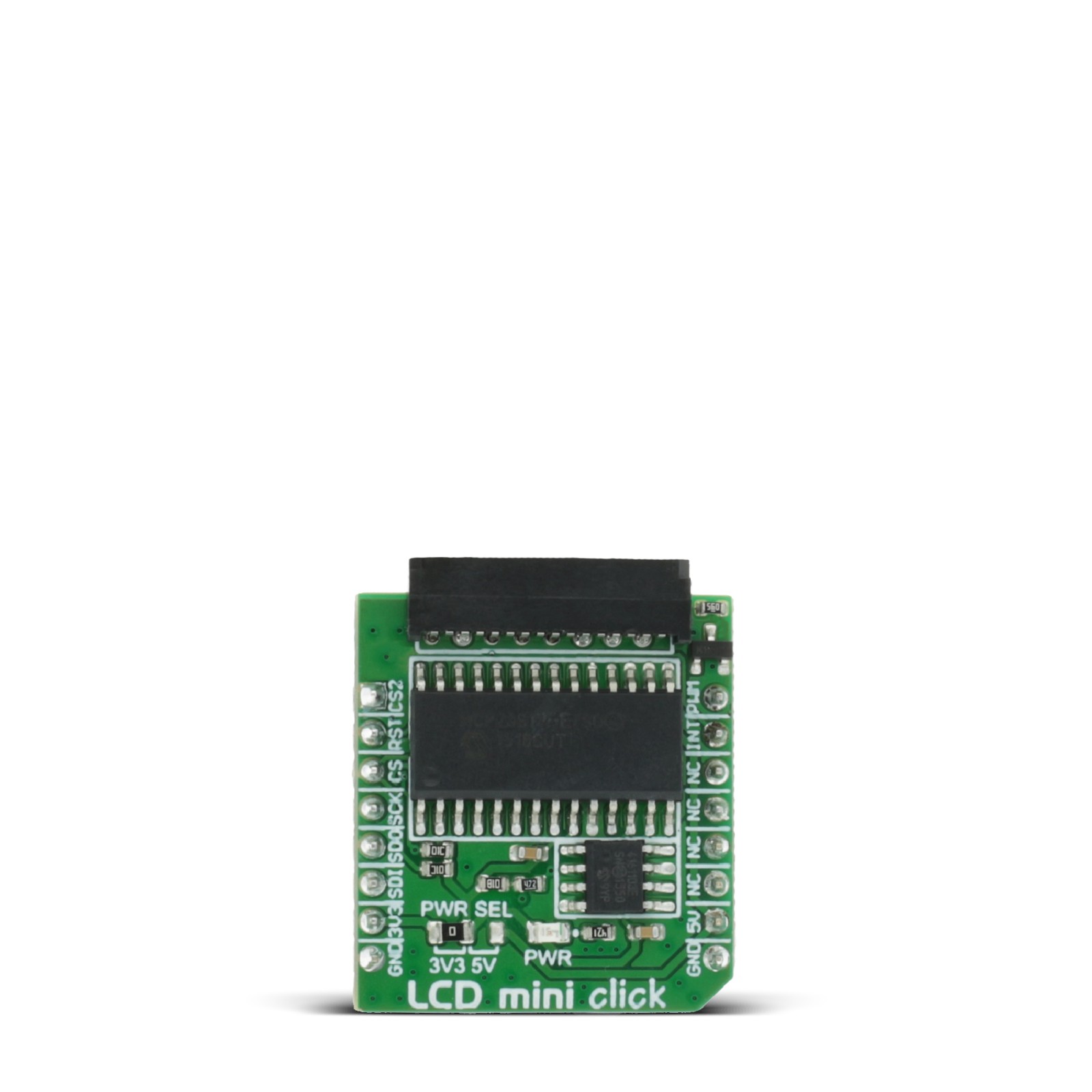
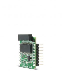
LCD Mini Click is based on the MCP23S17, a 16-bit I/O expander with a serial interface from Microchip. The MCP23S17 has an external reset input and a configurable interrupt source, which can also be configured as active-high or active-low. This bidirectional I2C expander bridges the host MCU and four data bit pins, an enable control pin, and a register select pin for the display. For it to work, the enable pin should be held HIGH. The register selects pin toggles between command mode (logic LOW) and data mode (logic HIGH). The brightness of the backlight LED can be controlled directly over the host MCU, but for the control of the contrast of the LCD, there is the MCP4161, an 8-bit single SPI digital POT with non-volatile memory from Microchip.
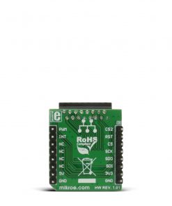
LCD Mini Click uses a standard 4-Wire SPI serial interface from both the I2C expander and the digital potentiometer to communicate with the host MCU. The MCP23S17 supports a high-speed SPI interface of up to 10MHz and can be selected over the CS pin and reset over the RST pin. It sends interrupts over the INT pin. The MCP4161 also supports high-speed SPI of up to 10MHz and can be selected over the CS2 pin. The PWM pin can be used to control the brightness of the LCD display’s backlight LED.
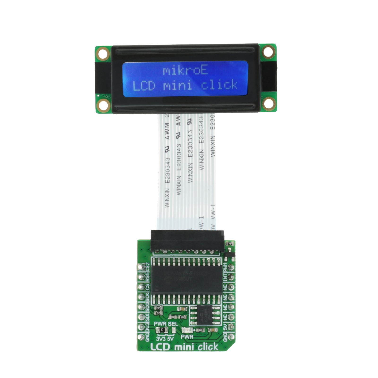
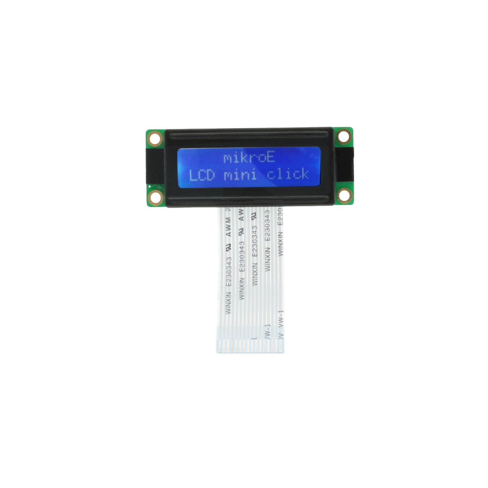
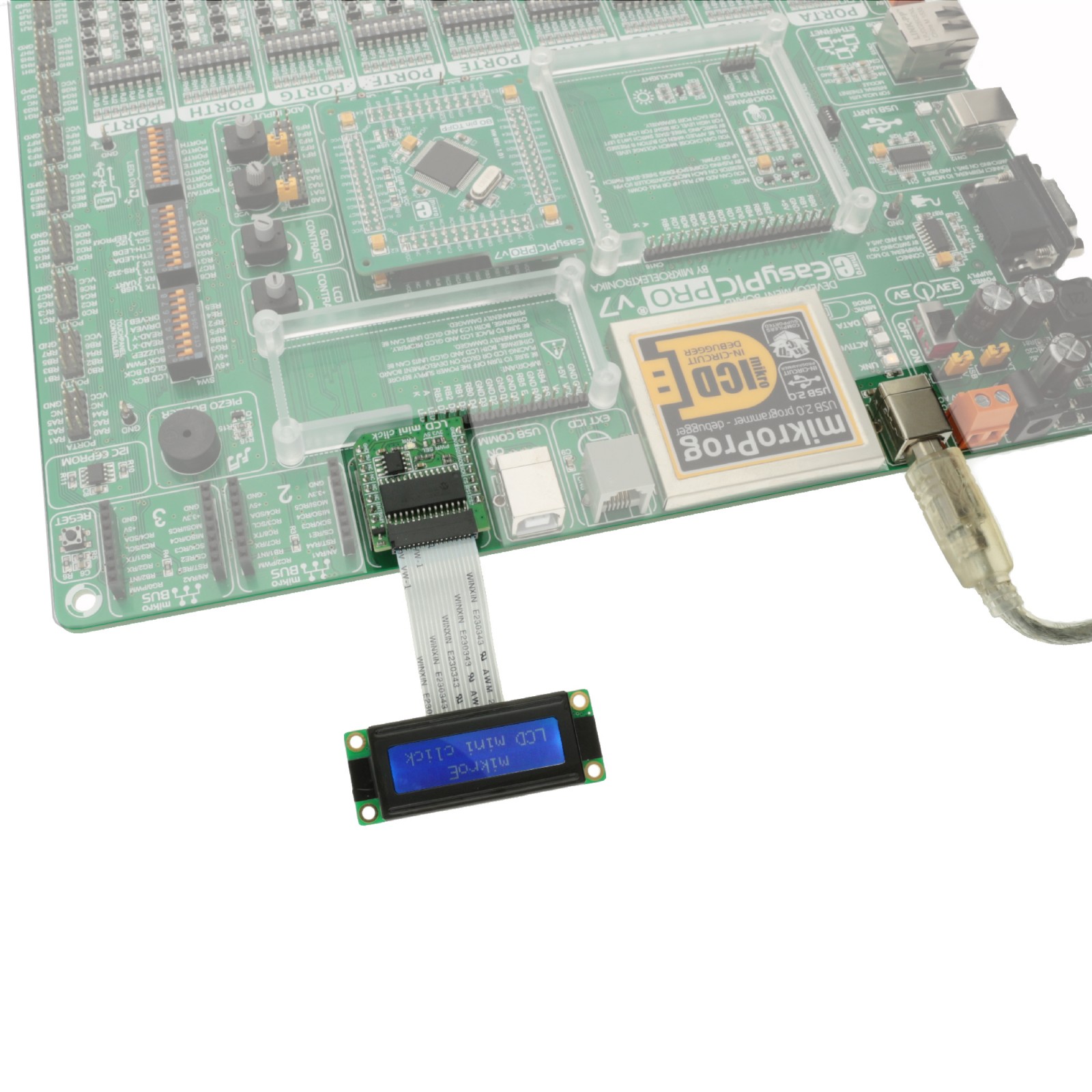
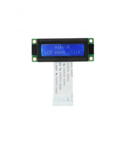
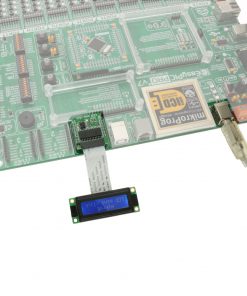
The LMB162XFW display with an appropriate cable does not come with the LCD Mini Click adapter board and is offered separately. However, the LCD Mini Click has an appropriate connector to interface the LCD display.
This Click board™ can operate with either 3.3V or 5V logic voltage levels selected via the PWR SEL jumper. This way, both 3.3V and 5V capable MCUs can use the communication lines properly. However, the Click board™ comes equipped with a library containing easy-to-use functions and an example code that can be used as a reference for further development.
Specifications
Type
Adapter,LCD
Applications
Can be used for developing short message information applications, user interfaces, control panels, and more
On-board modules
MCP23S17 – 16-bit I/O expander with a serial interface from Microchip
Key Features
Adapter Click boardTM for connecting 2×16 LCD displays, MCP23S17 I/O port expander, MCP4161 digital potentiometer, high-speed SPI interface of up to 10MHz, backlight brightness control, contrast control, register select between command mode and data mode, and more
Interface
GPIO,SPI
Feature
No ClickID
Compatibility
mikroBUS™
Click board size
S (28.6 x 25.4 mm)
Input Voltage
3.3V or 5V
Pinout diagram
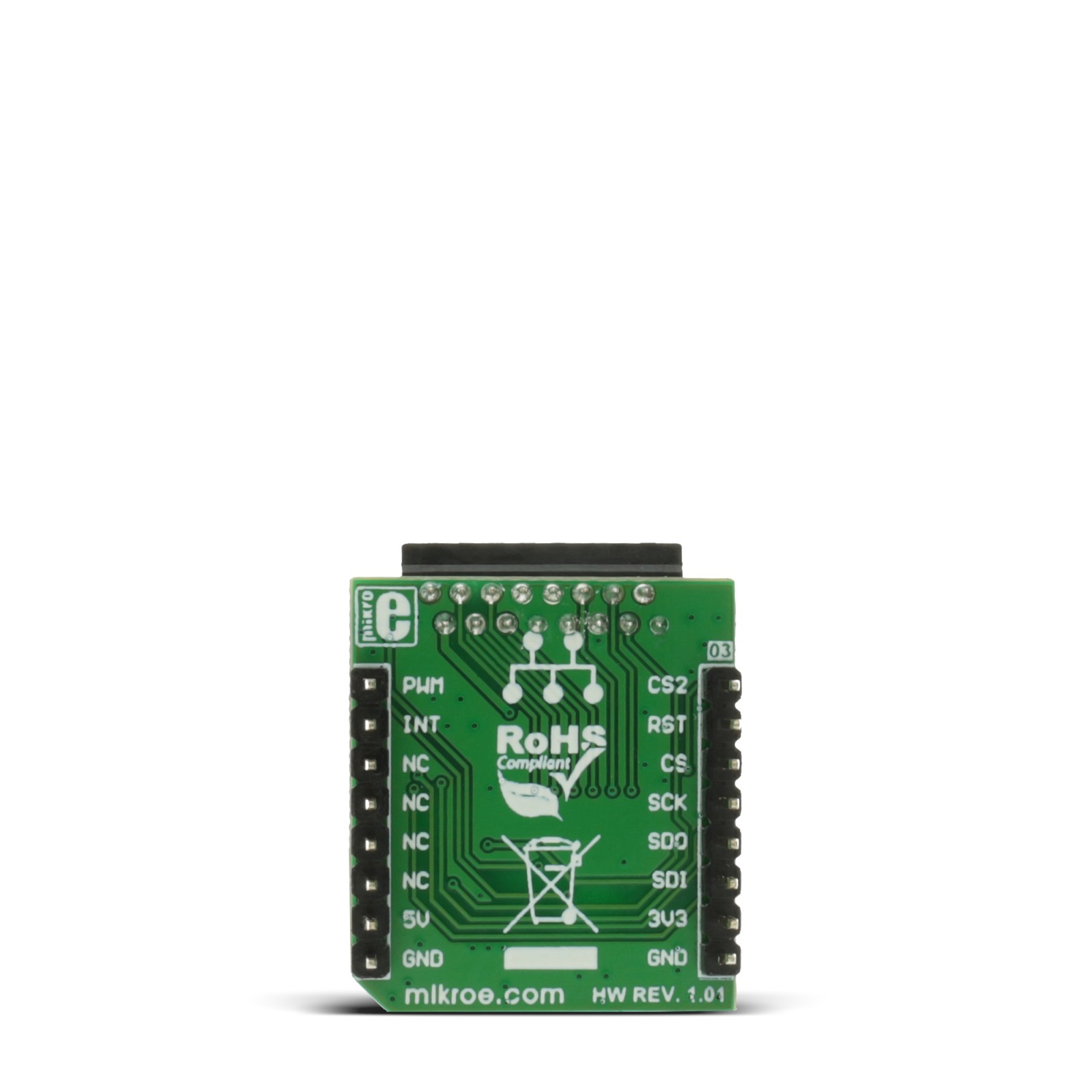
This table shows how the pinout on LCD mini Click corresponds to the pinout on the mikroBUS™ socket (the latter shown in the two middle columns).
Onboard settings and indicators
Label | Name | Default | Description |
---|---|---|---|
LD1 | PWR | – | Power LED Indicator |
JP1 | PWR SEL | Left | Logic Level Voltage Selection 3V3/5V: Left position 3V3, Right position 5V |
LCD mini Click electrical specifications
Description | Min | Typ | Max | Unit |
---|---|---|---|---|
Supply Voltage | 3.3 | – | 5 | V |
Software Support
We provide a library for the LCD mini Click as well as a demo application (example), developed using MIKROE compilers. The demo can run on all the main MIKROE development boards.
Package can be downloaded/installed directly from NECTO Studio Package Manager(recommended), downloaded from our LibStock™ or found on Mikroe github account.
Library Description
This library contains API for LCD mini Click driver.
Key functions
-
lcdmini_set_backlight
Set backlight function. -
lcdmini_set_contrast
Set contrast function. -
lcdmini_display_text
LCD mini display text.
Example Description
This is an example that demonstrates the use of the LCD mini Click board.
void application_task ( void )
{
Delay_ms( 500 );
lcdmini_send_cmd( &lcdmini, LCDMINI_SHIFT_LEFT );
}
The full application code, and ready to use projects can be installed directly from NECTO Studio Package Manager(recommended), downloaded from our LibStock™ or found on Mikroe github account.
Other Mikroe Libraries used in the example:
- MikroSDK.Board
- MikroSDK.Log
- Click.LCDmini
Additional notes and informations
Depending on the development board you are using, you may need USB UART click, USB UART 2 Click or RS232 Click to connect to your PC, for development systems with no UART to USB interface available on the board. UART terminal is available in all MIKROE compilers.
mikroSDK
This Click board™ is supported with mikroSDK – MIKROE Software Development Kit. To ensure proper operation of mikroSDK compliant Click board™ demo applications, mikroSDK should be downloaded from the LibStock and installed for the compiler you are using.
For more information about mikroSDK, visit the official page.