2x5W AMP Click
R425.00 ex. VAT
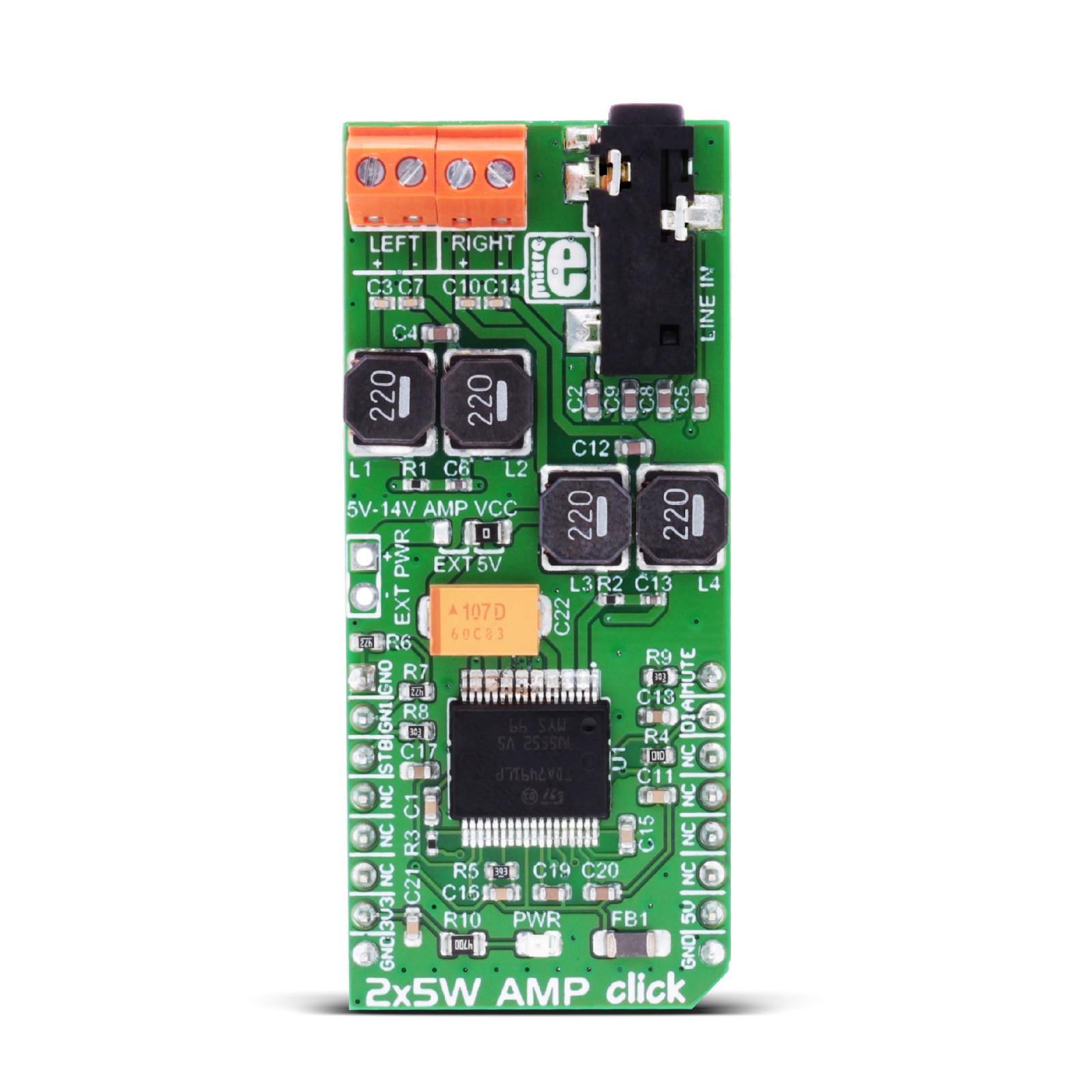
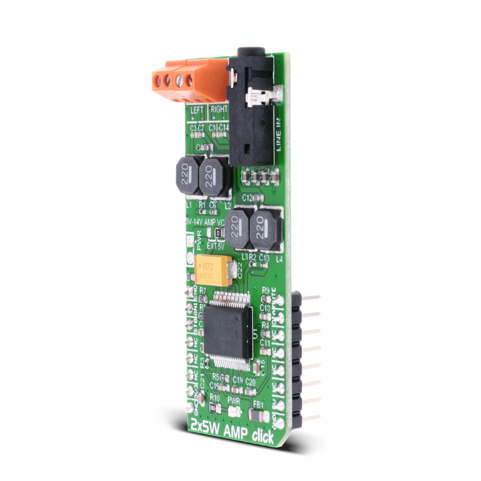
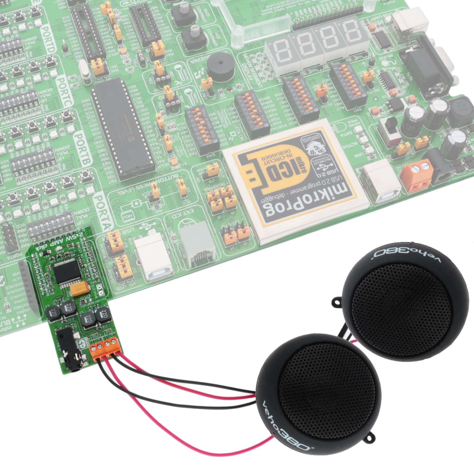
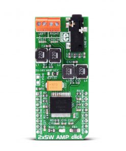
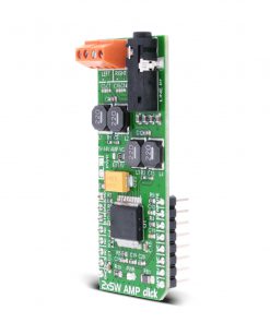
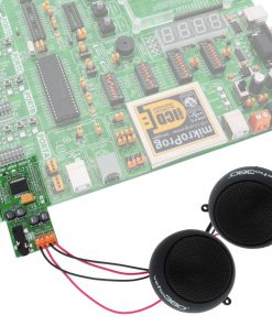
2x5W AMP Click is a compact add-on board that amplifies the audio input to the desired level. This board features the TDA7491LP, a 2×5 watt dual BTL class-D audio amplifier from STMicroelectronics. It can produce 5W + 5W continuous output power with high efficiency (90%) over a single power supply. Four selectable fixed gain settings are available to the user, nominally of 20dB, 26dB, 30dB, and 32dB. This Click board™ makes the perfect solution for the development of LCD TVs, monitors, sound systems, and more.
2x5W AMP Click is supported by a mikroSDK compliant library, which includes functions that simplify software development. This Click board™ comes as a fully tested product, ready to be used on a system equipped with the mikroBUS™ socket.
Stock: Lead-time applicable.
| 5+ | R403.75 |
| 10+ | R382.50 |
| 15+ | R361.25 |
| 20+ | R347.65 |
How does it work?
2x5W AMP Click is based on the TDA7491LP, a 2×5-watt dual BTL class-D audio amplifier from STMicroelectronics. It uses differential inputs to minimize common-mode noise and features filter-less operation. Furthermore, the filter-less operation allows a reduction in the external components. In addition, it features standby and mute, short circuits, undervoltage, overcurrent, and thermal overload protections, and no “pop” at turn-on/off. Thanks to the high efficiency and exposed-pad-down (EPD), it does not require a heatsink.
Class-D audio amplifiers (switching amplifiers) are very energy efficient. They reduce power losses on the output device by operating as an electronic switch rather than as linear gain devices, like in A or AB amplifiers. The output modulation scheme of the BTL is called unipolar pulse width modulation (PWM). An advantage of this scheme is that it effectively doubles the switching frequency of the differential output waveform on the load and then reduces the current ripple accordingly.
The two input pins set one of the three modes on TDA7491LP. The Standby mode has very low consumption, where all circuits are turned off. All inputs are connected to the ground in the Mute mode, and the positive and negative PWM outputs are in a 50% duty cycle. In the Play mode, all amplifiers are active. The gain is set over two GAIN inputs by combining logic states (the table is available in the attached datasheet).
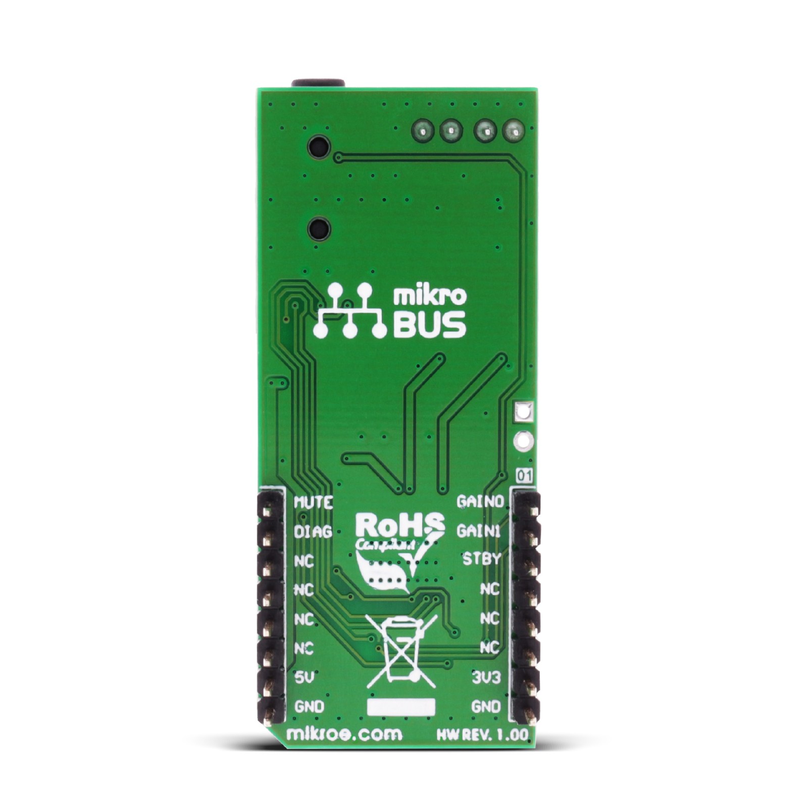
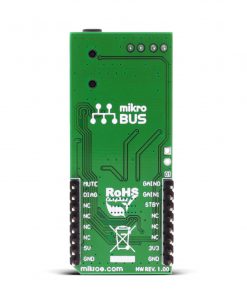
To communicate with the host MCU, the 2×5 AMP Click does not use standard serial communication; a few IO pins of the mikroBUS™ socket control it. Pins GN0 and GN1 are used to set the gain with a combination of logic states, according to the table in the datasheet. The STB and MUTE pins set the audio amplifier’s operating mode. The diagnostic output of the DIA pin has different behaviors depending on the various protection conditions.
To achieve full 2x5W output power, remember to supply enough power to the chip. This is achievable with the EXT PWR header, but you need to switch over the AMP VCC to the left position. Over the EXT PWR header, the 2×5 AMP Click can be powered with a wide-range single supply (5V – 14V).
This Click board™ can be operated only with a 5V logic voltage level. The board must perform appropriate logic voltage level conversion before using MCUs with different logic levels. Also, it comes equipped with a library containing functions and an example code that can be used as a reference for further development.
Specifications
Type
Amplifier
Applications
Can be used for the development of LCD TVs, monitors, sound systems, and more
On-board modules
TDA7491LP – 2×5-watt dual BTL class-D audio amplifier from STMicroelectronics
Key Features
2x5W output power, short-circuit, thermal overload, overcurrent, undervoltage protections, 3.5mm audio jack, screw terminals for passive speakers, four selectable fixed gains, three mode of operation, wide range single supply operation, filter-less operation, and more
Interface
GPIO
Feature
No ClickID
Compatibility
mikroBUS™
Click board size
L (57.15 x 25.4 mm)
Input Voltage
3.3V,5V
Pinout diagram
This table shows how the pinout on 2x5W AMP Click corresponds to the pinout on the mikroBUS™ socket (the latter shown in the two middle columns).
Onboard settings and indicators
| Label | Name | Default | Description |
|---|---|---|---|
| – | PWR | – | Power LED Indicator |
| – | AMP VCC | Right | Amplifier Power Source Selection EXT/5V: Left position EXT, Right position 5V |
2x5W AMP Click electrical specifications
| Description | Min | Typ | Max | Unit |
|---|---|---|---|---|
| Supply Voltage | – | 5 | – | V |
| External Power Supply | 5 | – | 14 | V |
| Output Power | – | – | 5 | W |
Software Support
We provide a library for the 2x5W_Amp Click on our LibStock page, as well as a demo application (example), developed using MIKROE compilers. The demo can run on all the main MIKROE development boards.
Library Description
The library covers all the necessary functions to control 2x5W Amp Click board. Library have drivers for setting one of three operating mode ( Standby, Mute or Play mode ) and for setting one of four amplifier gain ( 20dB, 26dB, 30dB or 32dB ) selection resistors.
Key functions:
uint8_t c2x5wamp_setMode( uint8_t selectMode )– Set mode selection of the amplifier functionvoid c2x5wamp_play()– Set Play mode of the amplifier functionvoid c2x5wamp_gain20dB()– Set amplifier gain to 20dB function
Examples description
The application is composed of three sections :
- System Initialization – Initializes GPIO and LOG structures, set INT pin as input and sets AN, RST, CS and PWM pins as output.
- Application Initialization – Initialization driver enable’s – GPIO and start write log.
- Application Task – (code snippet) This is a example which demonstrates the use of 2x5W Amp Click board. This examples first activates operation mode MUTE for 5 seconds and after that activates operation mode PLAY. When the device is in Play mode then changes the gain selection, first sets the minimum gain ( 20dB ) for 10 seconds and then sets the maximum gain ( 32dB ) for 5 seconds too. Results are being sent to the Usart Terminal where you can track their changes.
void applicationTask()
{
    c2x5wamp_mute();
    mikrobus_logWrite( "       MUTE  MODE      ", _LOG_LINE );
    Delay_ms( 5000 );
    mikrobus_logWrite( "-----------------------", _LOG_LINE );

    if (c2x5wamp_setMode(_C2X5WAMP_MODE_PLAY))
    {
        mikrobus_logWrite( "       PLAY  MODE       ", _LOG_LINE );
    }
    else
    {
        mikrobus_logWrite( "    ERROR PLAY MODE    ", _LOG_LINE );
    }
    mikrobus_logWrite( "-----------------------", _LOG_LINE );

    c2x5wamp_gain20dB();
    mikrobus_logWrite( "   Gain set to  20dB   ", _LOG_LINE );
    Delay_ms( 10000 );
    mikrobus_logWrite( "- - - - - - - - - - - -", _LOG_LINE );

    c2x5wamp_gain32dB();
    mikrobus_logWrite( "   Gain set to  32dB   ", _LOG_LINE );
    Delay_ms( 5000 );
    mikrobus_logWrite( "-----------------------", _LOG_LINE );
}
The full application code, and ready to use projects can be found on our LibStock page.
Other mikroE Libraries used in the example:
- GPIO
- UART
Additional notes and informations
Depending on the development board you are using, you may need USB UART click, USB UART 2 click or RS232 click to connect to your PC, for development systems with no UART to USB interface available on the board. The terminal available in all MIKROE compilers, or any other terminal application of your choice, can be used to read the message.
mikroSDK
This Click board™ is supported with mikroSDK - MIKROE Software Development Kit. To ensure proper operation of mikroSDK compliant Click board™ demo applications, mikroSDK should be downloaded from the LibStock and installed for the compiler you are using.
For more information about mikroSDK, visit the official page.
Resources
Downloads
| Weight | 25 g |
|---|---|
| Brand | MikroElektronika |

