How does it work?
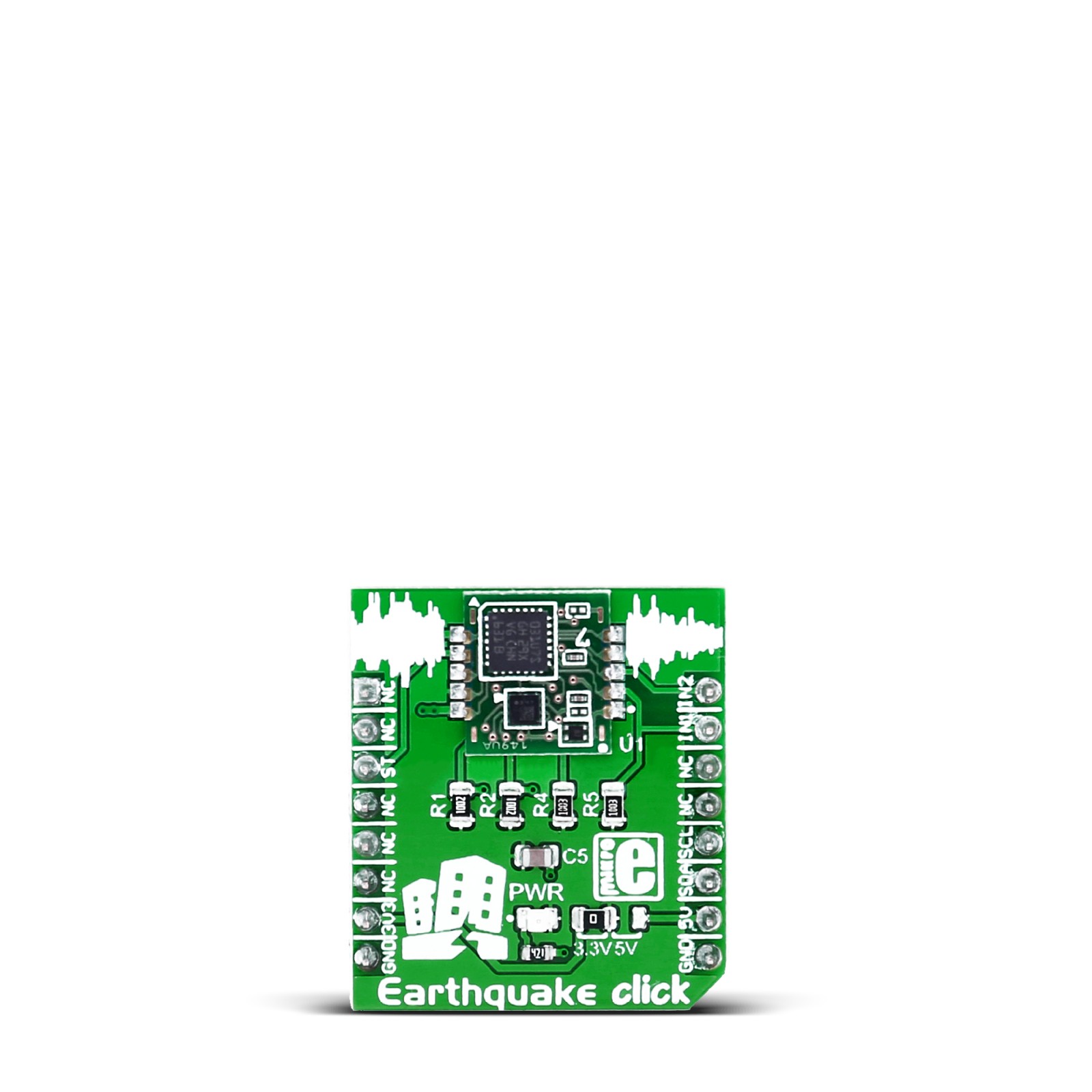
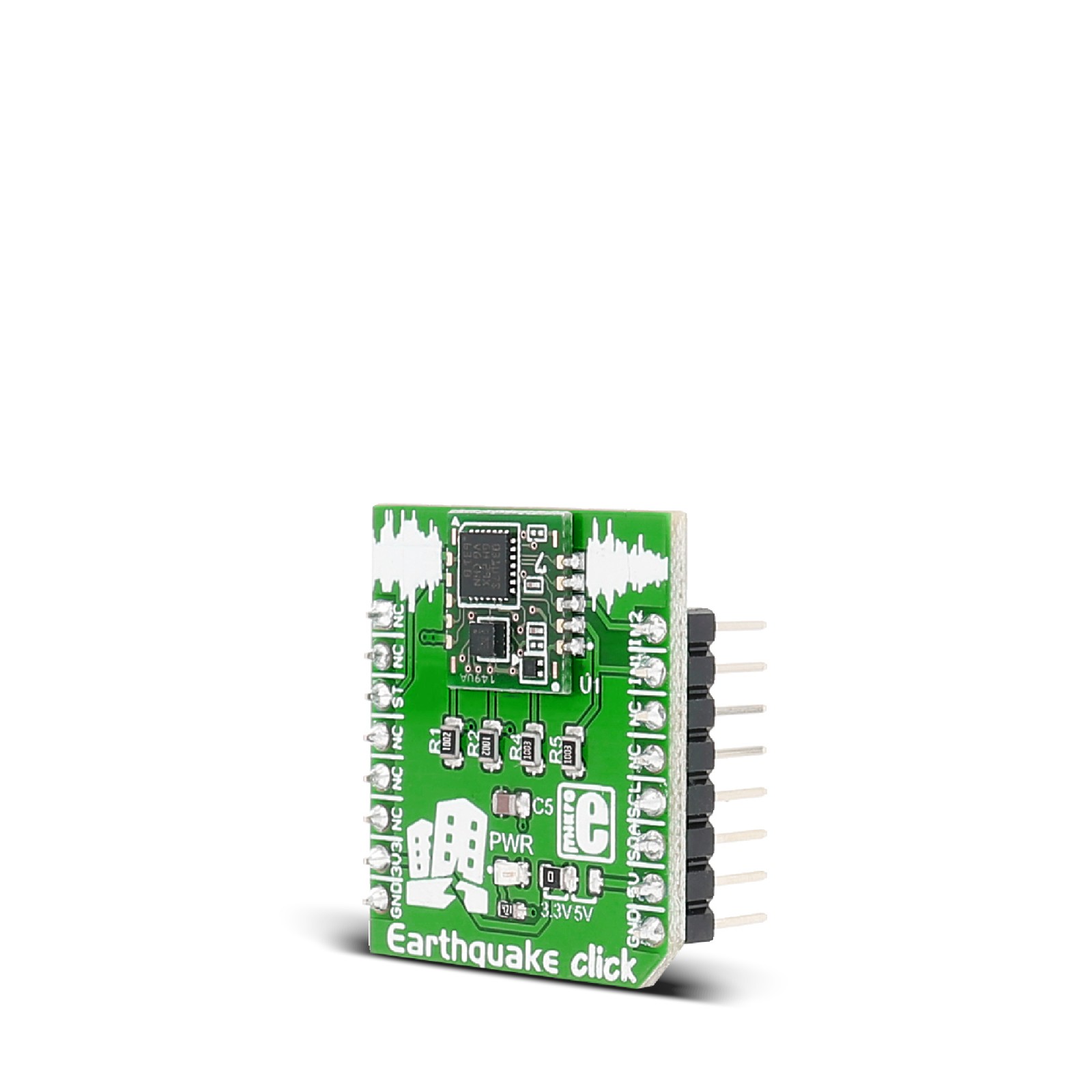
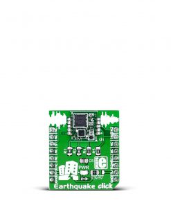
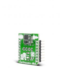
Earthquake Click is based on the D7S, the world’s smallest class-size high-precision seismic sensor from OMRON. It uses the SI (spectral intensity) value, which has a high correlation with the seismic intensity scale that indicates the magnitude of an earthquake and provides higher-precision judgment of seismic intensity scales. When an earthquake occurs with a seismic intensity equivalent to 5 Upper or higher on the JMA (Japan Meteorological Agency) Seismic Intensity Scale, the D7S will activate the shutoff output to notify the user of an earthquake.
JMA, or Japan Meteorological Agency intensity scale, is used in Japan and Taiwan to measure the intensity of earthquakes. The scale goes from 0 to 7. The level 5 on this scale indicates when objects inside a house start falling down, like books from the shelf, dishes in a cupboard, cracks formed on walls, and more.
Earthquake Click uses a standard 2-Wire I2C interface to communicate with the host MCU. The shutoff terminal on IN1 will go active (ON) when the shutoff judgment condition and collapse detection condition are met. The processing notification output IN2 will go active (ON) during the earthquake calculations, offset acquisition, and self-diagnostic processing. The initial setting input ST changes the sensor from Normal mode to Initial Installation mode for input from an external device.
This Click board™ can operate with either 3.3V or 5V logic voltage levels selected via the 3.3V 5V jumper. This way, both 3.3V and 5V capable MCUs can use the communication lines properly. However, the Click board™ comes equipped with a library containing easy-to-use functions and an example code that can be used as a reference for further development.
Specifications
Type
Motion,Vibration
Applications
Can be used for the development of vibration sensors, fire prevention systems, electricity meters, gas meters, applications for chemical plants, bridges, tunnels, and more
On-board modules
D7S – high-precision seismic sensor from OMRON
Key Features
Small size, low power consumption, shutoff output at seismic intensity SI level 5 or higher, wide acceleration range, three-axis acceleration sensor, and Omron’s unique SI value calculation algorithm to determine the seismic intensity scale, and more
Interface
I2C
Feature
No ClickID
Compatibility
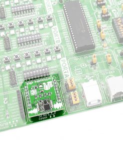
mikroBUS™
Click board size
S (28.6 x 25.4 mm)
Input Voltage
3.3V or 5V
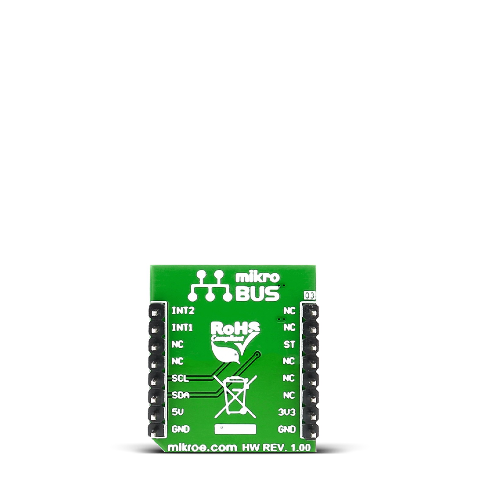
Pinout diagram
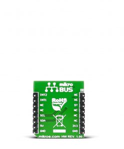
This table shows how the pinout on Earthquake click corresponds to the pinout on the mikroBUS™ socket (the latter shown in the two middle columns).
Onboard settings and indicators
Label | Name | Default | Description |
---|---|---|---|
LD1 | PWR | – | Power LED Indicator |
JP1 | 3.3V 5V | Left | Logic Level Voltage Selection 3V3/5V: Left position 3V3, Right position 5V |
Earthquake click electrical specifications
Description | Min | Typ | Max | Unit |
---|---|---|---|---|
Supply Voltage | 3.3 | – | 5 | V |
Acceleration Detection Range | -2000 | – | 2000 | gal |
Software Support
We provide a library for the Earthquake Click as well as a demo application (example), developed using MIKROE compilers. The demo can run on all the main MIKROE development boards.
Package can be downloaded/installed directly from NECTO Studio Package Manager(recommended), downloaded from our LibStock™ or found on Mikroe github account.
Library Description
This library contains API for Earthquake Click driver.
Key functions
-
earthquake_proc_notify
Shutoff output function. -
earthquake_read_status
Read status function. -
earthquake_read_si
Read SI function.
Example Description
Intializes I2C module, LOG and GPIO structure, sets INT and PWM pins as input and sets CS pin as output.
void application_task ( void )
{
if ( earthquake_proc_notify( &earthquake ) )
{
log_printf( &logger, " Earthquake detected! rn" );
log_printf( &logger, "------------------------rn" );
Delay_ms ( 1000 );
Delay_ms ( 1000 );
for ( cnt = 20; cnt > 0; cnt-- )
{
log_printf( &logger, " Status : " );
display_status( earthquake_read_status( &earthquake ) );
read_data = earthquake_read_si( &earthquake );
log_printf( &logger, " Max SI : %drn", read_data );
log_printf( &logger, "------------------------ rn" );
Delay_ms ( 1000 );
Delay_ms ( 1000 );
Delay_ms ( 1000 );
Delay_ms ( 1000 );
Delay_ms ( 1000 );
}
earthquake_clear_memory( &earthquake );
log_printf( &logger, " Afterquake processing rn" );
log_printf( &logger, " please wait... rn" );
Delay_ms ( 1000 );
Delay_ms ( 1000 );
Delay_ms ( 1000 );
Delay_ms ( 1000 );
Delay_ms ( 1000 );
Delay_ms ( 1000 );
Delay_ms ( 1000 );
Delay_ms ( 1000 );
Delay_ms ( 1000 );
Delay_ms ( 1000 );
Delay_ms ( 1000 );
Delay_ms ( 1000 );
Delay_ms ( 1000 );
Delay_ms ( 1000 );
Delay_ms ( 1000 );
Delay_ms ( 1000 );
Delay_ms ( 1000 );
Delay_ms ( 1000 );
Delay_ms ( 1000 );
Delay_ms ( 1000 );
log_printf( &logger, "------------------------rn" );
log_printf( &logger, " Waiting for a quake... rn" );
log_printf( &logger, "------------------------rn" );
}
}
The full application code, and ready to use projects can be installed directly from NECTO Studio Package Manager(recommended), downloaded from our LibStock™ or found on Mikroe github account.
Other Mikroe Libraries used in the example:
- MikroSDK.Board
- MikroSDK.Log
- Click.Earthquake
Additional notes and informations
Depending on the development board you are using, you may need USB UART click, USB UART 2 Click or RS232 Click to connect to your PC, for development systems with no UART to USB interface available on the board. UART terminal is available in all MIKROE compilers.
mikroSDK
This Click board™ is supported with mikroSDK – MIKROE Software Development Kit. To ensure proper operation of mikroSDK compliant Click board™ demo applications, mikroSDK should be downloaded from the LibStock and installed for the compiler you are using.
For more information about mikroSDK, visit the official page.