How does it work?
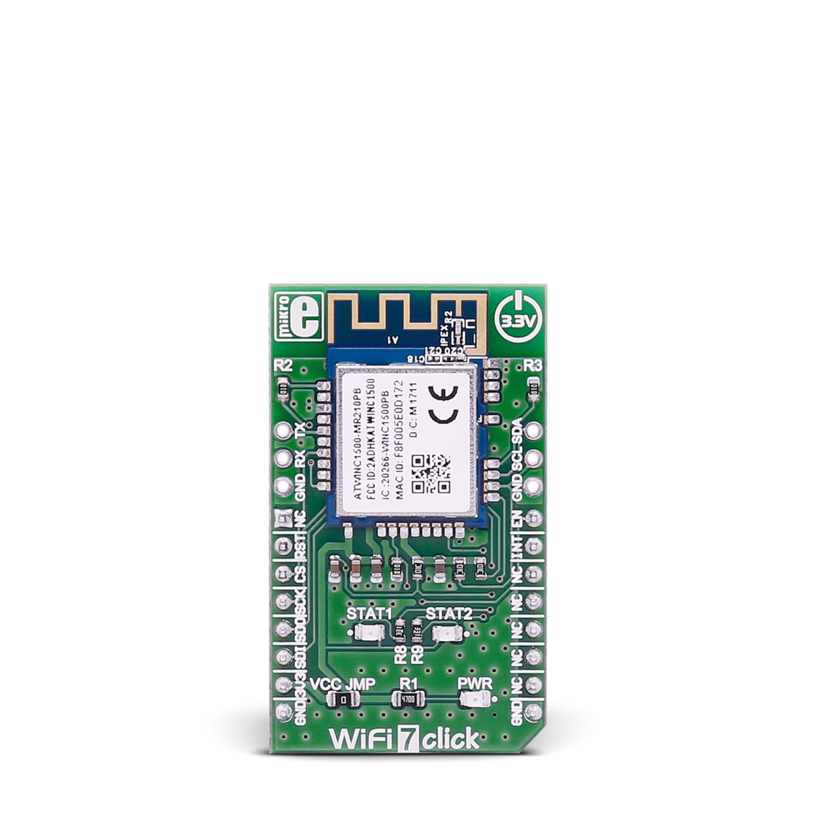
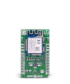
WiFi 7 Click is based on the ATWINC1510-MR210PB, an IEEE 802.11 b/g/n IoT Module from Microchip. Under the metal hood, there is a Cortus APS3 32-bit processor that performs many MAC functions, including but not limited to association, authentication, power management, security key management, and MSDU aggregation/de-aggregation. It also provides flexibility for various modes of operation, such as STA and AP modes. The processor has 128KB of instruction/boot ROM, 160KB of instruction RAM, and 64KB of data RAM. In addition, it has 4Mb of flash memory, which can be used for system software. The APS3 can perform various data management tasks on the RX and TX data packets as it can access 128KB of shared RAM with the MAC.
In security terms, the ATWINC1510-MR210PB comes with datapath engines. The FCS engine checks the CRC of the transmitting and receiving packets, while the cipher engine performs the encryption and decryption operations for the WEP, WPA-TKIP, WPA2 CCMP-AES, and WAPI. Depending on the 802.11 standard, the module uses DSSS-CCK, OFDM, or HT modulation.
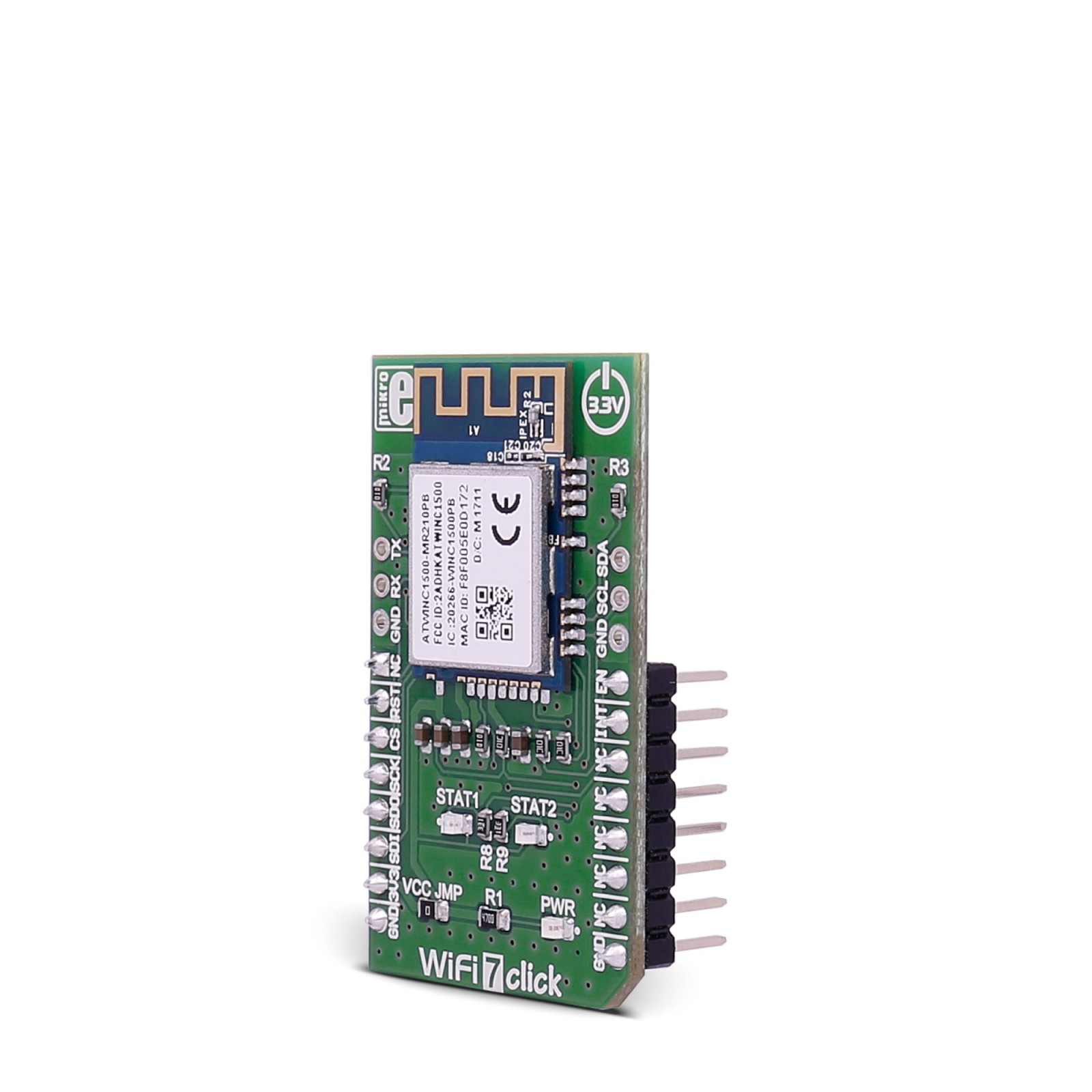
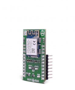
WiFi 7 Click comes with two headers that allow you to access RX/TX UART of the ATWINC1510-MR210PB module for firmware update and the I2C interface for debugging. There are also two status LEDs, STAT1 and STAT2, which can be configured to present some of the features of the ATWINC1510-MR210PB module, such as AURT RX and TX communication.
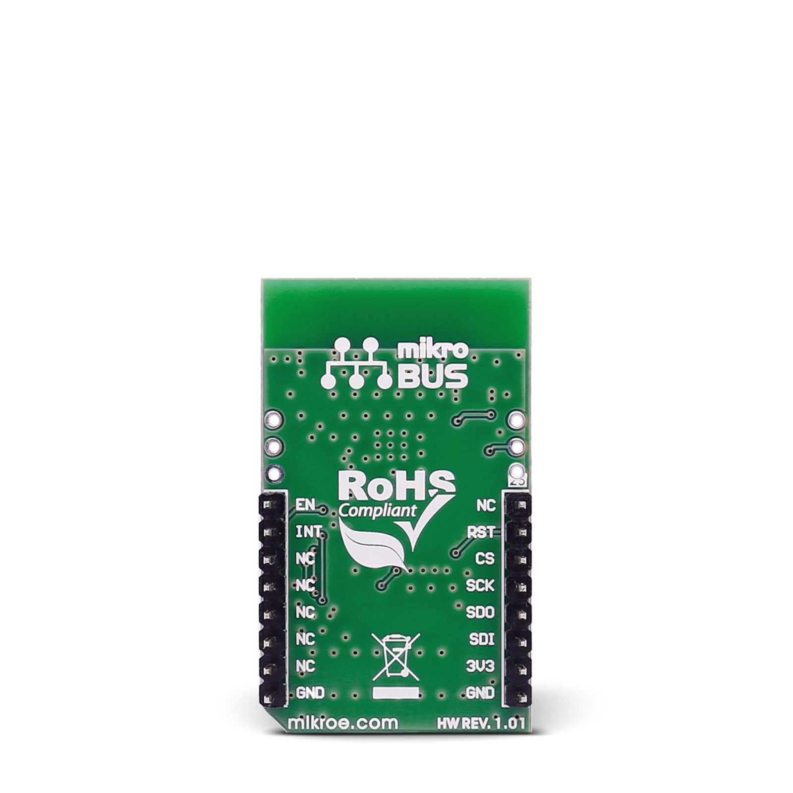
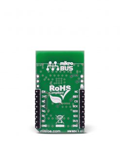
WiFi 7 Click uses a standard 4-Wire SPI serial interface to communicate with the host MCU. Additional pins are RST for resetting the device, EN to enable it, and an interrupt INT pin that will notify the host MCU of various error conditions.
This Click board™ can be operated only with a 3.3V logic voltage level. The board must perform appropriate logic voltage level conversion before using MCUs with different logic levels. However, the Click board™ comes equipped with a library containing functions and an example code that can be used as a reference for further development.
Specifications
Type
BT/BLE,WiFi
Applications
Can be used for the development of highly integrated, cost-effective applications that require wireless communication, such as IoT devices, industrial wireless control, smart home devices, and more
On-board modules
ATWINC1510-MR210PB – IEEE 802.11 b/g/n IoT Module from Microchip
Key Features
IEEE 802.11b/g/n 2.4GHz ISM band, integrated printed PCB antenna, Wi-Fi Direct, and Soft-AP support, 2 OR 2-Wire Bluetooth coexistence, WEP, WPA, and WPA2 security, integrated flash memory, 32-bit processor, OTA, integrated network IP stack, TCP, UDP, DHCP, ARP, HTTP, SSL, and DNS, and more
Interface
GPIO,SPI
Feature
No ClickID
Compatibility
mikroBUS™
Click board size
M (42.9 x 25.4 mm)
Input Voltage
3.3V
Pinout diagram
This table shows how the pinout on WiFi 7 Click corresponds to the pinout on the mikroBUS™ socket (the latter shown in the two middle columns).
Onboard settings and indicators
Label | Name | Default | Description |
---|---|---|---|
– | PWR | – | Power LED Indicator |
– | STAT1 | – | User Configured Status 1 LED Indicator |
– | STAT2 | – | User Configured Status 2 LED Indicator |
WiFi 7 Click electrical specifications
Description | Min | Typ | Max | Unit |
---|---|---|---|---|
Supply Voltage | – | 3.3 | – | V |
Operating Frequency Range | 2.412 | – | 2.4835 | GHz |
Data Rate | – | – | 72.2 | Mbps |