How does it work?
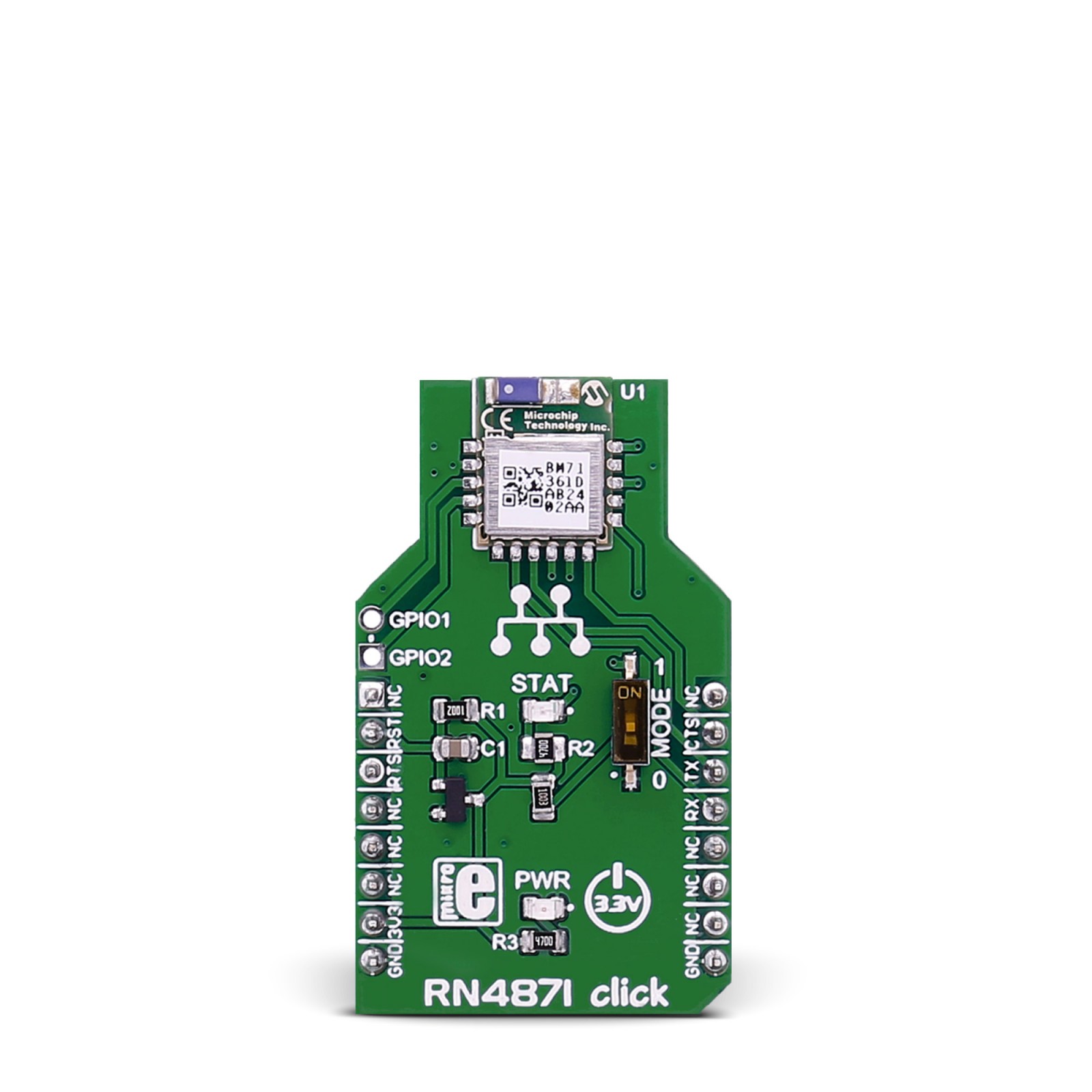
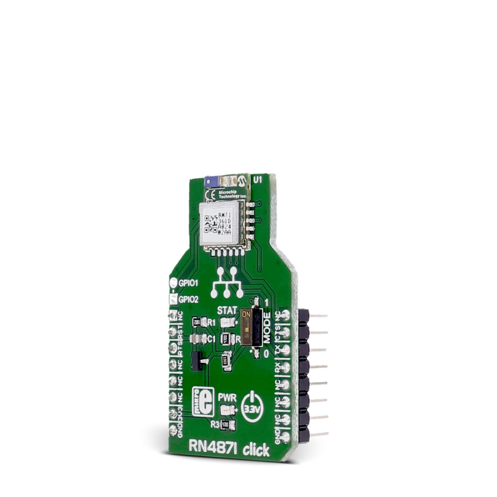
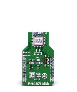
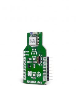
RN4871 Click is based on the RN4871, a Bluetooth 4.2 low-energy module from Microchip. The Bluetooth radio works in 2402 up to 2480 GHz range and is secured with AES128 encryption. The user can create up to five public and four private services. In addition, the module features GAP, GATT, SM, L2CAP, and integrated public profiles. It can be configured by software as a Peripheral or Central and Client or Server. The onboard MODE switch is a system configuration input that allows you to enter application mode or test mode for Flash updates and EEPROM settings. The module will indicate whether the module is on/off over the STAT LED.
RN4871 Click uses a standard UART interface to communicate with the host MCU with commonly used UART RX and TX pins. In addition, it uses UART control flow pins UART CTS and RTS. Besides our available software, you can communicate with the RN4871 using a set of ASCII commands. Besides used communication pins, two additional user-configurable GPIO pins are provided on the unpopulated GPIO header.
This Click board™ can be operated only with a 3.3V logic voltage level. The board must perform appropriate logic voltage level conversion before using MCUs with different logic levels. However, the Click board™ comes equipped with a library containing functions and an example code that can be used as a reference for further development.
Specifications
Type
BT/BLE
Applications
Can be used for the development of health/medical devices, sports activity/fitness meters, beacon applications, internet of Things (IoT)sensor tags, remote controls, wearable smart devices and accessories, and more
On-board modules
RN4871 – Bluetooth 4.2 low-energy module from Microchip
Key Features
ASCII command interface API over UART, Bluetooth 4.2 with Low Energy stack, Secure AES128 encryption, GAP, GATT, SM, L2CAP, and integrated public profiles, custom up to five public and four private services, software configurable role as Peripheral or Central, and Client or Server, and more
Interface
I2C,UART
Feature
No ClickID
Compatibility
mikroBUS™
Click board size
M (42.9 x 25.4 mm)
Input Voltage
3.3V
Pinout diagram
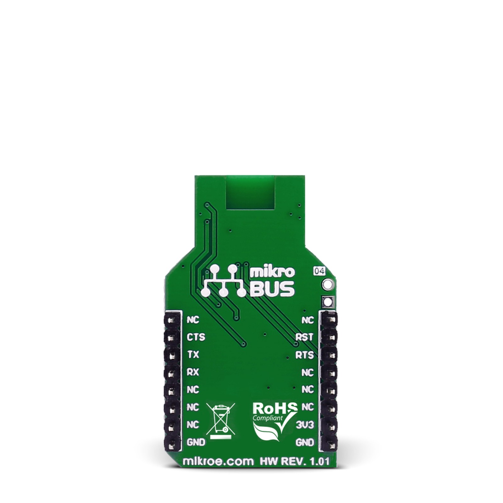
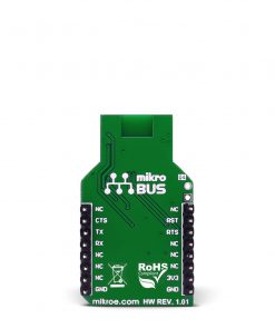
This table shows how the pinout on RN4871 click corresponds to the pinout on the mikroBUS™ socket (the latter shown in the two middle columns).
Onboard settings and indicators
Label | Name | Default | Description |
---|---|---|---|
LD1 | PWR | – | Power LED Indicator |
LD2 | STAT | – | Module Active State LED Indicator |
SW1 | MODE | Lower | System Configuration Selection 1/0: Upper position 1, Lower position 0 |
RN4871 Click electrical specifications
Description | Min | Typ | Max | Unit |
---|---|---|---|---|
Supply Voltage | – | 3.3 | – | V |
Frequency Range | 2402 | – | 2480 | MHz |
Data Rate | – | – | 10 | Kbps |
Software Support
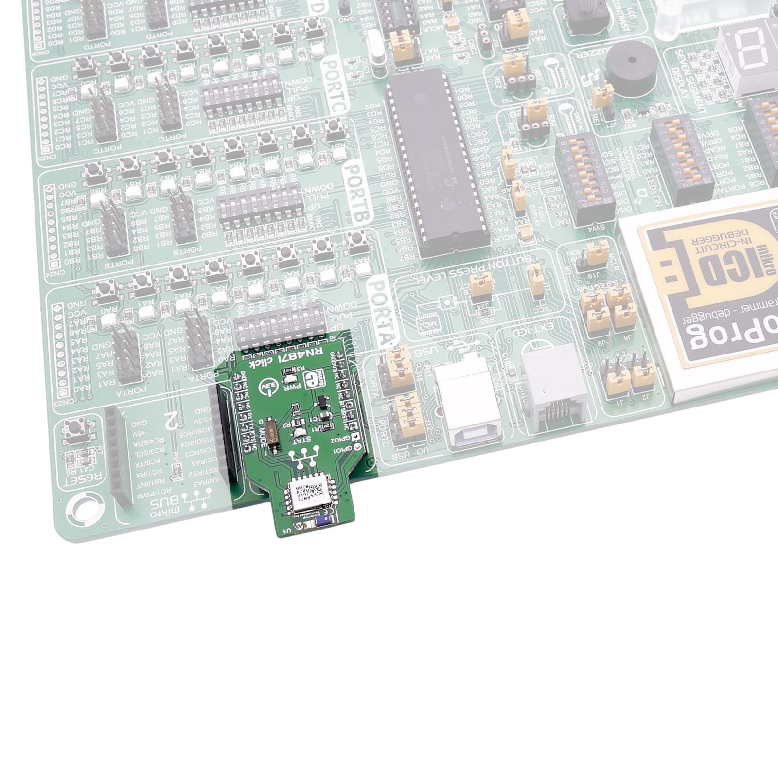
We provide a library for the RN4871 Click as well as a demo application (example), developed using MIKROE compilers. The demo can run on all the main MIKROE development boards.
Package can be downloaded/installed directly from NECTO Studio Package Manager(recommended), downloaded from our LibStock™ or found on Mikroe github account.
Library Description
This library contains API for RN4871 Click driver.
Key functions
-
This function gets message from ‘void rn4871_receive function if flag was set. This function replaces ‘*’ (character with end of string) with ‘0x00’ and stores received message to process_buffer
-
The function receives character by waits for ‘#’ – character to start parsing message, waits for ‘*’ – character to stop parsing message and sets flag if whole and properly formated message is received.
-
The function connects to slave device with desired register address by secures the connection and entering data stream mode.
Example Description
This example reads and processes data from RN4871 clicks.
void application_task ( void )
{
rn4871_process( );
if ( dev_type == RN4871_DEVICETYPE_MASTER )
{
rn4871_connect( &rn4871, &RN4871_ADDR_SLAVE[ 0 ] );
log_printf( &logger, ">>> sending data <<<rn" );
rn4871_send( &rn4871, RN4871_MTYPE_MSG, RN4871_DTYPE_STRING, RN4871_ID_MASTER, &message_payload[ 0 ] );
rn4871_disconnect( &rn4871 );
}
else if ( dev_type == RN4871_DEVICETYPE_SLAVE )
{
msg_flag = rn4871_read( &rn4871, &receive_buffer[ 0 ] );
if ( msg_flag == 1 )
{
log_printf( &logger, ">>> data received <<<rn" );
log_printf( &logger, ">>> data : " );
log_printf( &logger, "%srn", ptr );
}
}
}
The full application code, and ready to use projects can be installed directly from NECTO Studio Package Manager(recommended), downloaded from our LibStock™ or found on Mikroe github account.
Other Mikroe Libraries used in the example:
- MikroSDK.Board
- MikroSDK.Log
- Click.Rn4871
Additional notes and informations
Depending on the development board you are using, you may need USB UART click, USB UART 2 Click or RS232 Click to connect to your PC, for development systems with no UART to USB interface available on the board. UART terminal is available in all MIKROE compilers.
mikroSDK
This Click board™ is supported with mikroSDK – MIKROE Software Development Kit. To ensure proper operation of mikroSDK compliant Click board™ demo applications, mikroSDK should be downloaded from the LibStock and installed for the compiler you are using.
For more information about mikroSDK, visit the official page.