How does it work?
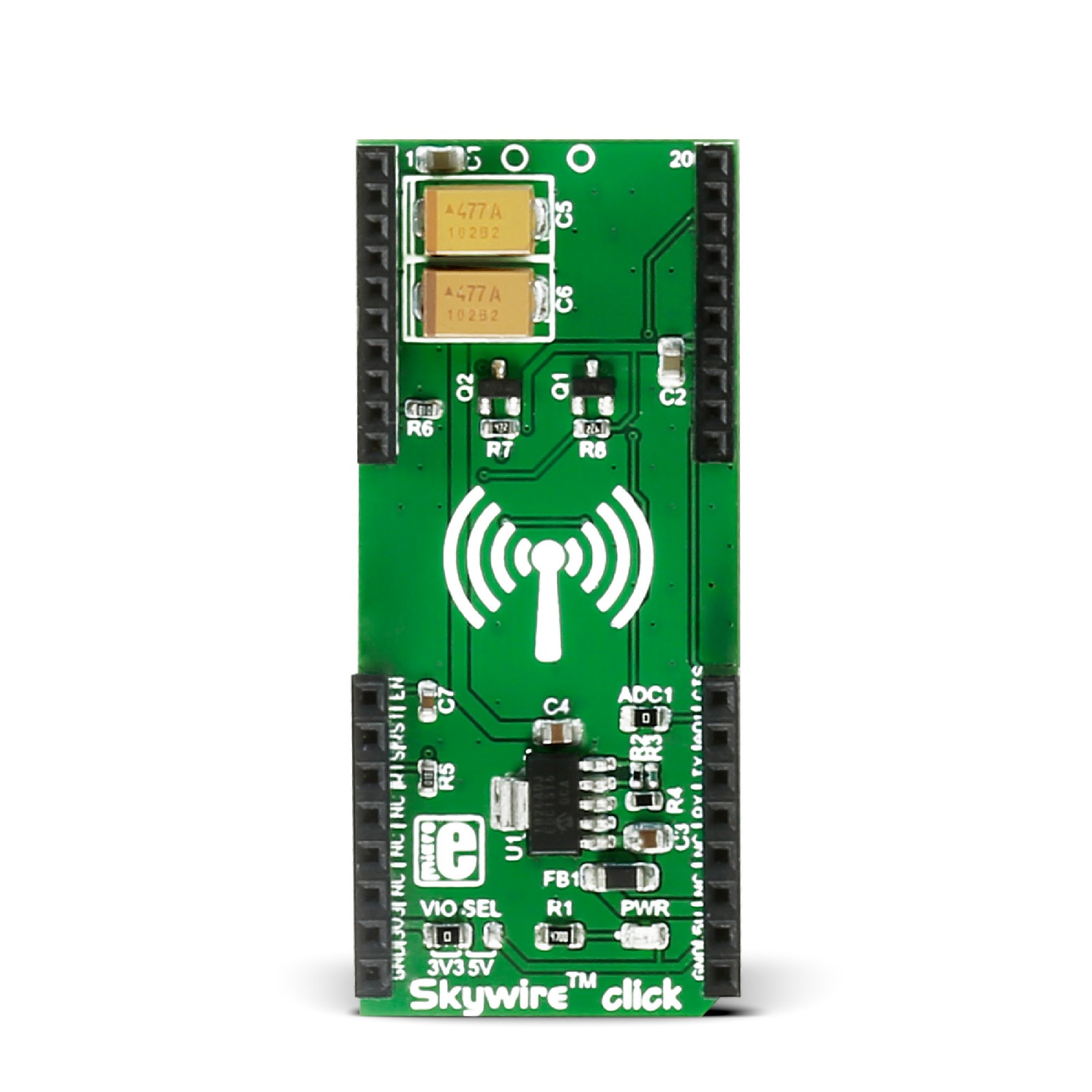
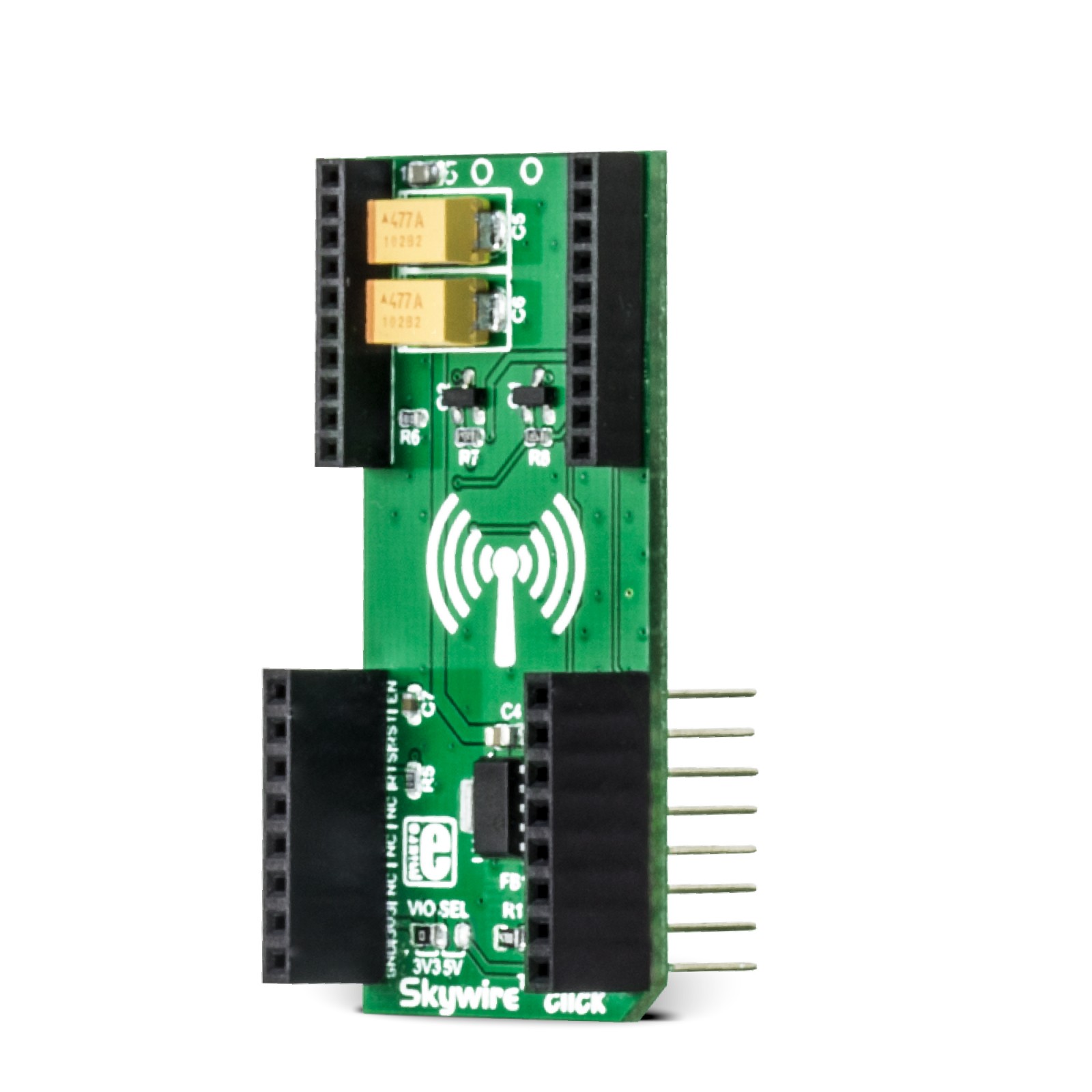
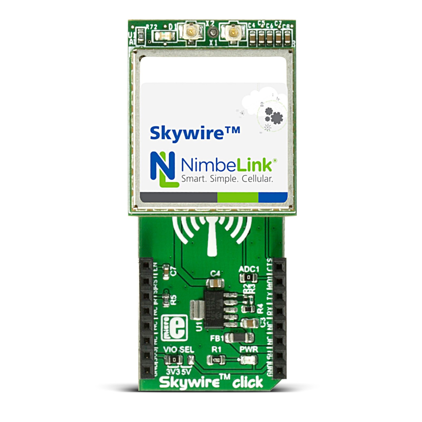
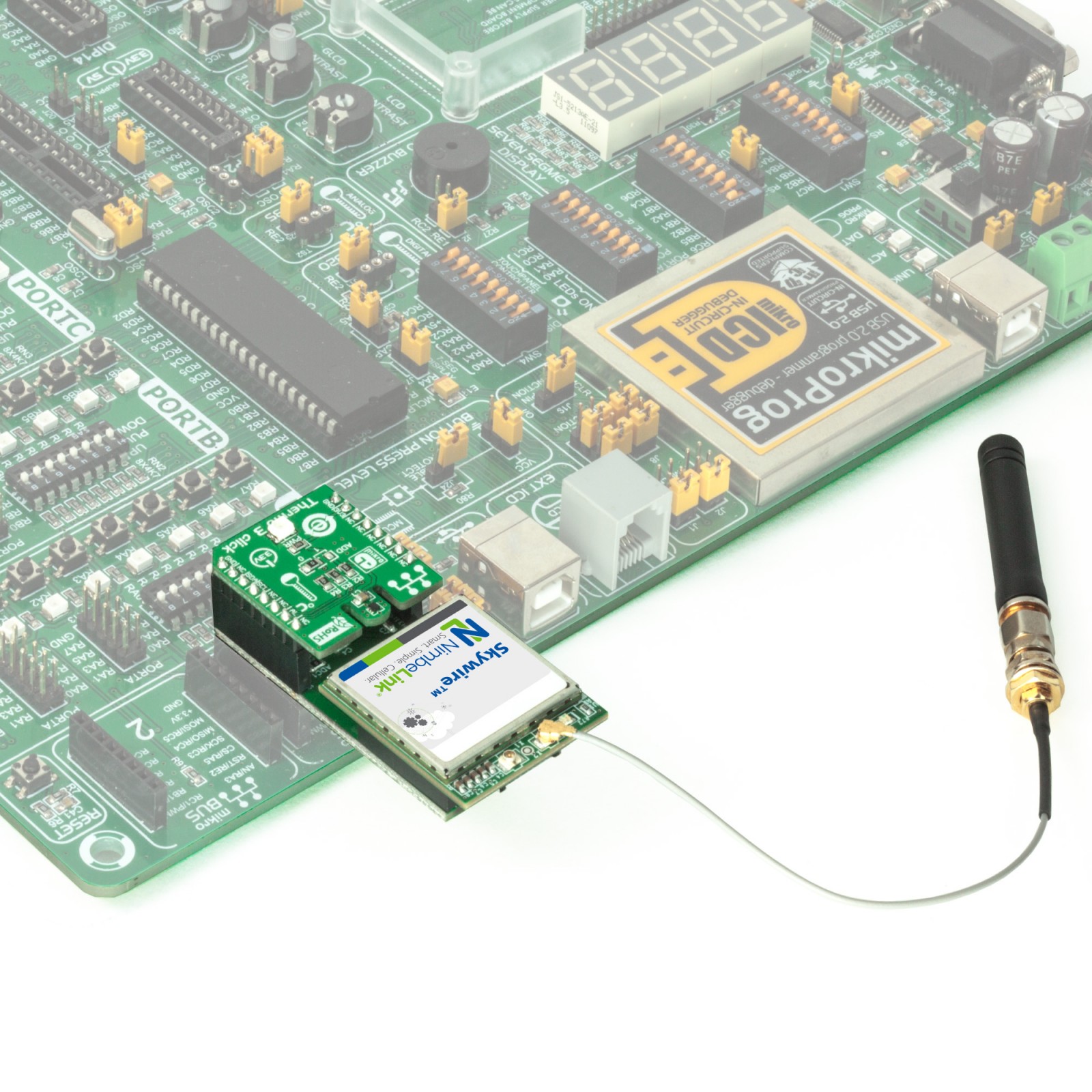
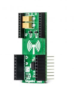
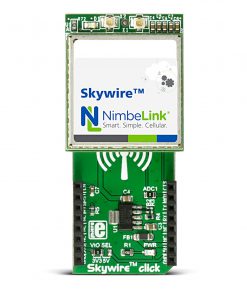
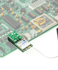
Skywire Click is based on double-row headers that allow stacking one of Airgain’s modem family, covering everything from 2G and 3G to LTE. The NimbeLink/Skywire includes a dozen modems with the same compact footprint and pinout. This fact simplifies the design of the applications, in addition to a MIKROE Click board™ boards and development boards portfolio. The combination can result in endless numbers of possibilities.
The Skywire Click is equipped with the MCP1826, a low-voltage, low-quiescent current LDO regulator from Microchip. This LDO provides the needed voltage for the modems. The selected logic level is connected to the external system IO reference input of the NimbeLink/Skywire modems, as it should match the host MCU IO voltage level. The VREF pin of the module will draw less than 1mA when the modem is powered.
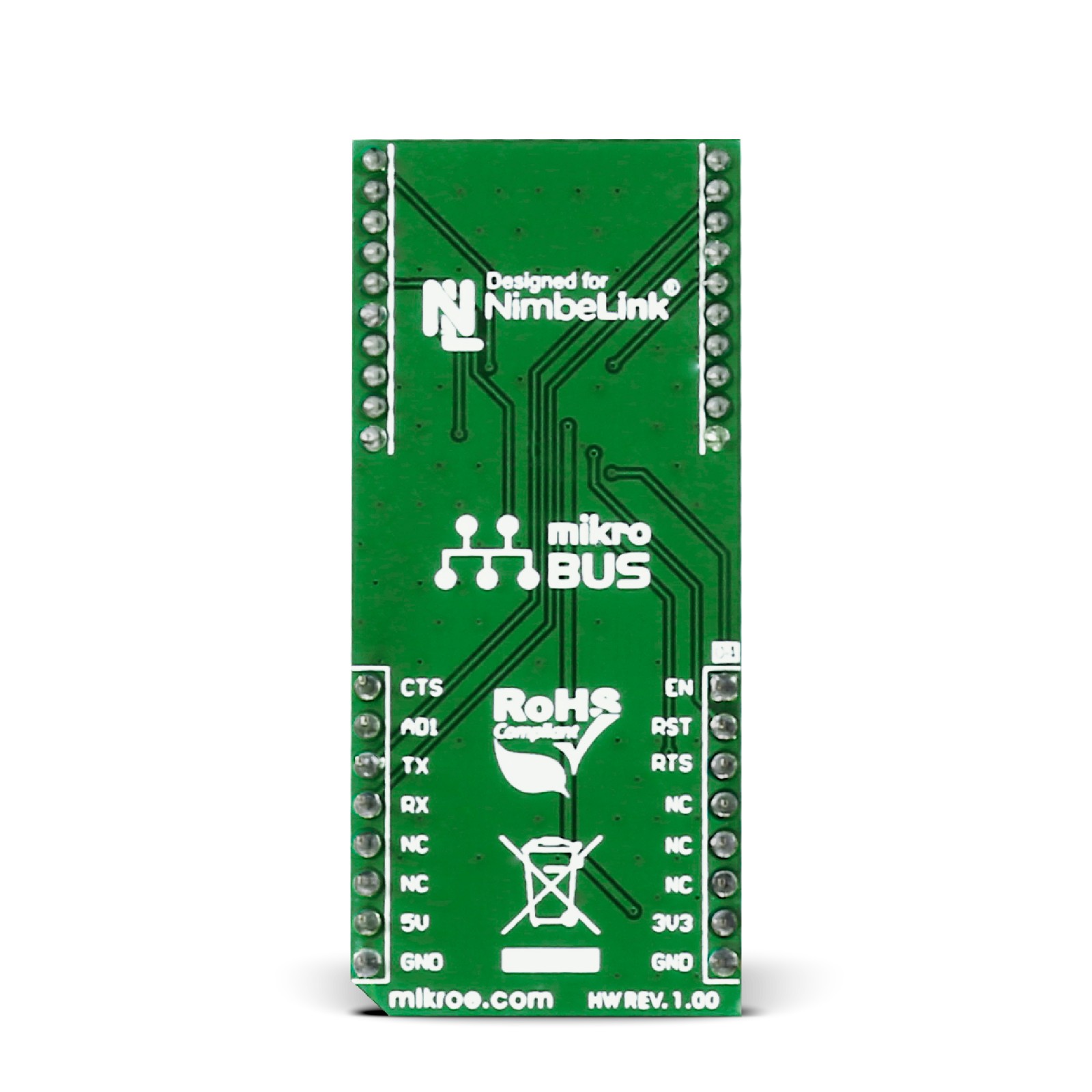
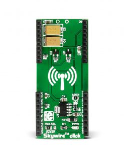
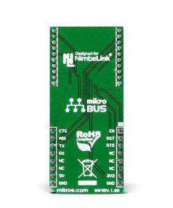
The NimbeLink/Skywire modems on top of the Skywire Click adapter use the standard UART interface with commonly used UART RX and TX pins to communicate with the host MCU. In addition to the RX and TX pins, the UART flow control RTS and CTS pins are also available. Some additional pins are available on Click board™, such as the reset RST pin and enable EN pin. There is also an ADC input pin to the modem on ADI of the mikroBUS™ socket, which supports 8-bit or 10-bit resolution depending on the modem. In addition, the CAT M1 NimbeLink, instead of the ADC, has a ring feature on this pin. Before further development, please consult the modem’s exact datasheet. If you do not need this feature, you can unsolder the 0 Ohm resistor and use this pin as a standard interrupt or GPIO pin for additional Click board™.
This Click board™ can operate with either 3.3V or 5V logic voltage levels selected via the VIO SEL jumper. This way, both 3.3V and 5V capable MCUs can use the communication lines properly.
Specifications
Type
Adapter
Applications
Developemnt of 2G, 3G or LTE applications by using Skywire cellular modems
On-board modules
MCP1826 LDO regulator
Key Features
Additional socket for mini sized click board™, MCP1826 LDO regulator, 3.3V or 5V power supply
Interface
GPIO,UART
Feature
No ClickID
Compatibility
mikroBUS™
Click board size
L (57.15 x 25.4 mm)
Input Voltage
3.3V or 5V
Pinout diagram
This table shows how the pinout on Skywire click corresponds to the pinout on the mikroBUS™ socket (the latter shown in the two middle columns).
Onboard settings and indicators
Label | Name | Default | Description |
---|---|---|---|
LD1 | PWR | – | Power LED Indicator |
JP1 | VIO SEL | Left | Logic Level Voltage Selection 3V3/5V: Left position 3V3, Right position 5V |
– | ADC1 | Populated | Enables ADC Input of the module to the AD1 pin |
Skywire Click electrical specifications
Description | Min | Typ | Max | Unit |
---|---|---|---|---|
Supply Voltage | 3.3 | – | 5 | V |