How does it work?
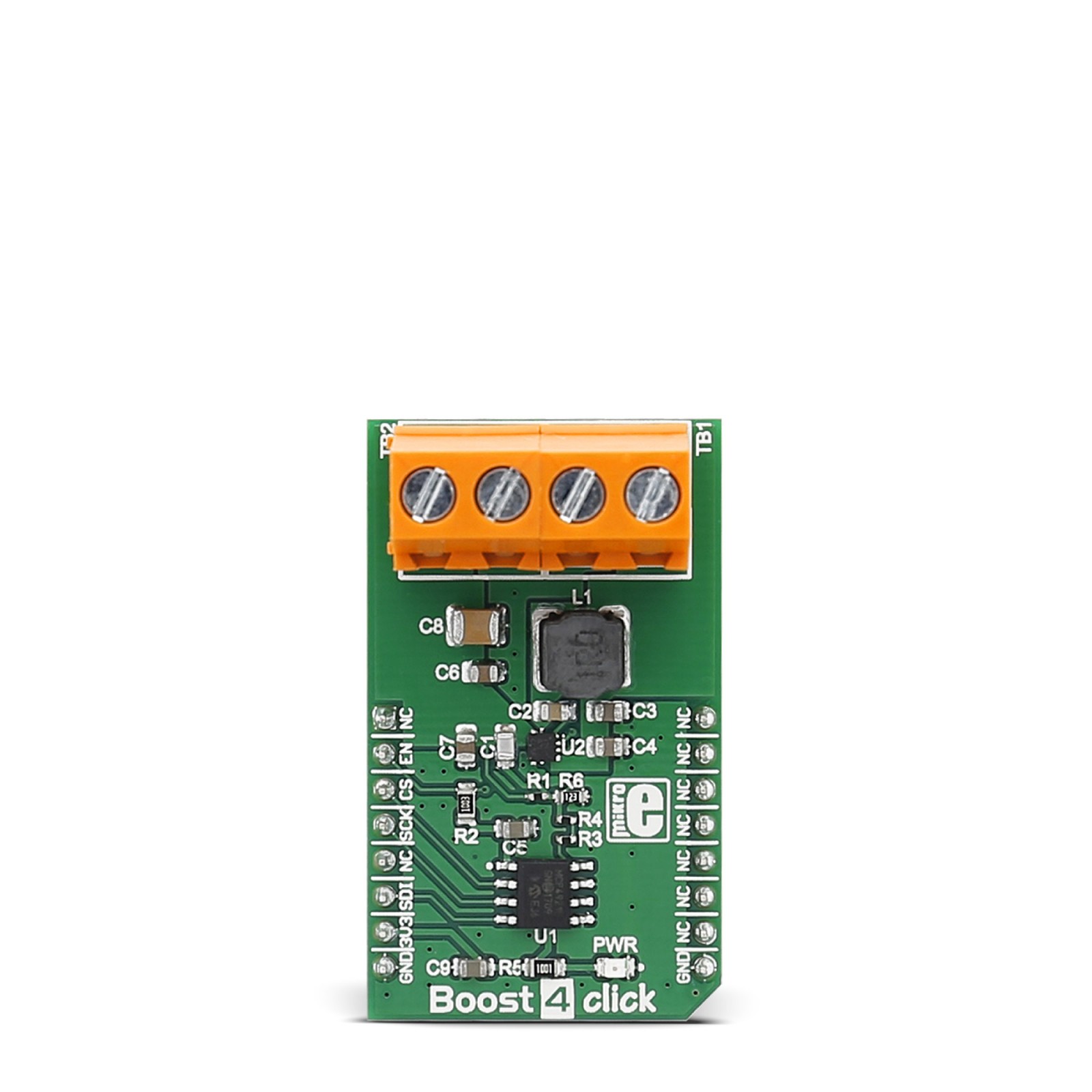
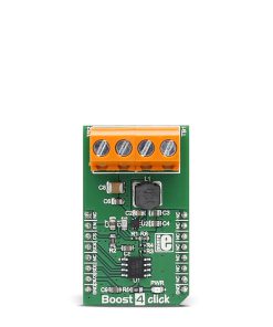
Boost 4 Click is based on the TPS61230A, a high-efficiency step-up converter from Texas Instruments. It works at 1.15MHz, the typical operating frequency, and provides an adjustable output voltage via the MCP4921, a 12-bit DAC with an SPI interface from Microchip. While working in light conditions, the converter automatically enters into the PFM operation to maximize efficiency. When the output is shorted, the converter enters the hiccup protection mode and recovers automatically when the output short is released. In addition, the TPS61230A features output over-voltage protection, thermal shutdown protection, soft start time, and more.
Boost 4 Click uses a standard 3-Wire SPI serial interface of the MCP4921 to communicate with the host MCU, with 20MHz clock support. The SPI interface of the DAC supports Mode 0,0 and Mode 1,1. The DAC drives the adjustable feedback for the converter’s output voltage. The step-up converter is enabled by default over the pull-up resistor, but you can disable it by driving LOW logic on the EN pin of the mikroBUS™ socket.
This Click board™ can be operated only with a 3.3V logic voltage level. The board must perform appropriate logic voltage level conversion before using MCUs with different logic levels. However, the Click board™ comes equipped with a library containing functions and an example code that can be used as a reference for further development.
Specifications
Type
Boost
Applications
Can be used for the development of power banks, USB power supplies, tablet PCs, audio power amplifiers, battery-powered products, and more
On-board modules
TPS61230A – high-efficiency step-up converter from Texas Instruments
Key Features
Screw terminals for input and output voltages, DAC for adjustable output voltage, thermal shutdown, over-voltage protection, output short protection, true load disconnect, PFM operation at the light load, quasi-constant switching frequency, two 21-mΩ (LS) / 18-mΩ (HS) MOSFETs, and more
Interface
SPI
Feature
No ClickID
Compatibility
mikroBUS™
Click board size
M (42.9 x 25.4 mm)
Input Voltage
3.3V
Pinout diagram
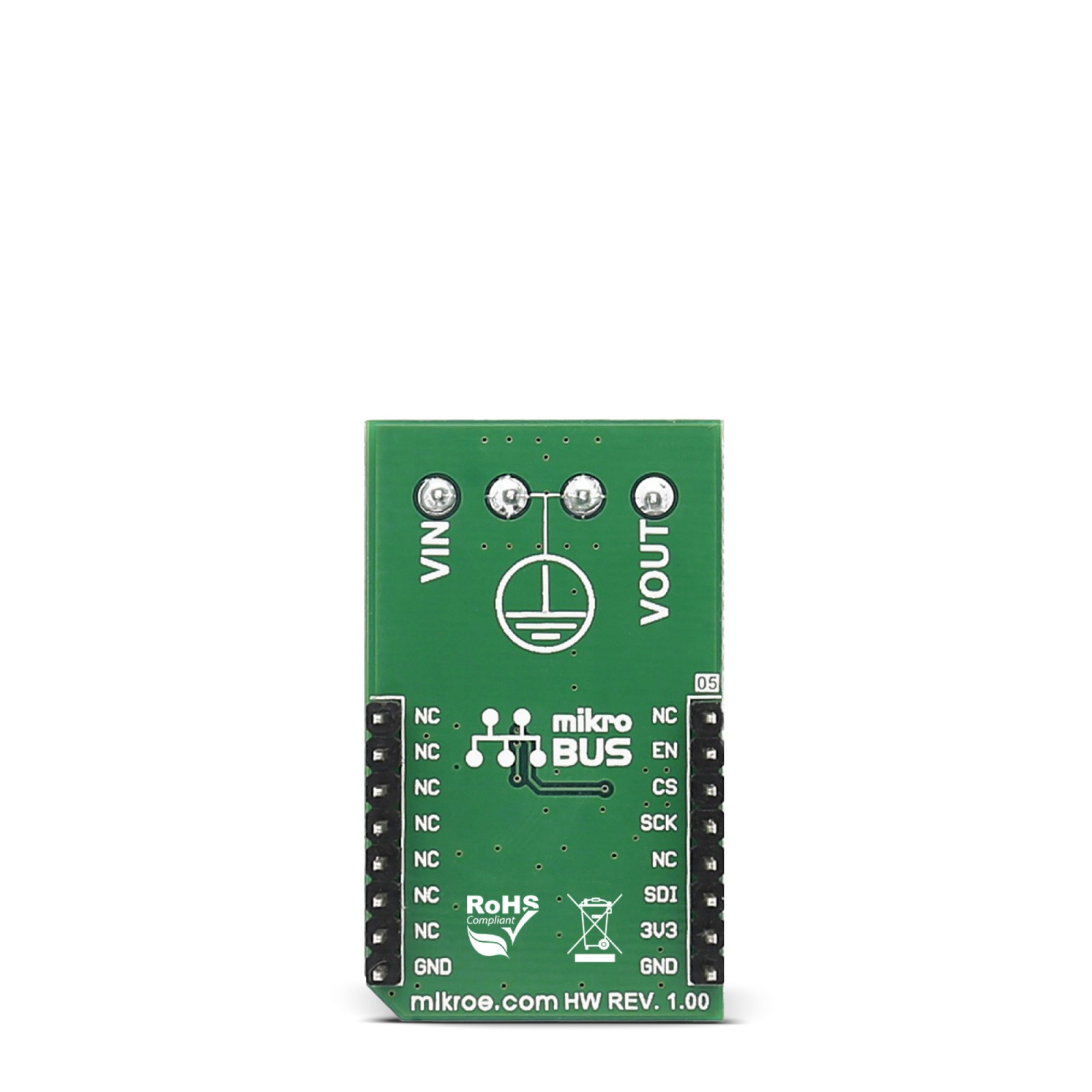
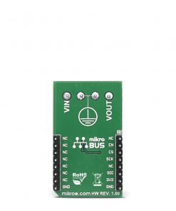
This table shows how the pinout on Boost 4 click corresponds to the pinout on the mikroBUS™ socket (the latter shown in the two middle columns).
Onboard settings and indicators
Label | Name | Default | Description |
---|---|---|---|
LD1 | PWR | – | Power LED Indicator |
Boost 4 click electrical specifications
Description | Min | Typ | Max | Unit |
---|---|---|---|---|
Supply Voltage | – | 3.3 | – | V |
Input Voltage | 2.5 | – | 4.5 | V |
Output Voltage | 2.5 | – | 5.5 | V |
Output Current Rating | – | – | 2.4 | A |
Software Support
We provide a library for the Boost 4 Click as well as a demo application (example), developed using MIKROE compilers. The demo can run on all the main MIKROE development boards.
Package can be downloaded/installed directly from NECTO Studio Package Manager(recommended), downloaded from our LibStock™ or found on Mikroe github account.
Library Description
This library contains API for Boost 4 Click driver.
Key functions
-
Generic SPI transfer, for sending and receiving packages.
-
Function set output voltage by write 12-bit data to the register on the TPS61230A High Efficiency Step-Up Converter of Boost 4 Click.
-
Function is used to enabled or disabled the device.
Example Description
This example demonstrates the use of Boost 4 Click board.
void application_task ( void )
{
log_printf( &logger, " Set the max Vout rn" );
boost4_set_out_voltage( &boost4, BOOST4_VOUT_MAX );
Delay_ms( 3000 );
log_printf( &logger, "-----------------------------rn" );
log_printf( &logger, " Set Vout to 5Vrn" );
boost4_set_out_voltage( &boost4, BOOST4_VOUT_5 );
Delay_ms( 3000 );
log_printf( &logger, "-----------------------------rn" );
log_printf( &logger, " Set Vout to 4.5Vrn" );
boost4_set_out_voltage( &boost4, BOOST4_VOUT_4_5 );
Delay_ms( 3000 );
log_printf( &logger, "-----------------------------rn" );
log_printf( &logger, " Set Vout to 4Vrn" );
boost4_set_out_voltage( &boost4, BOOST4_VOUT_4 );
Delay_ms( 3000 );
log_printf( &logger, "-----------------------------rn" );
log_printf( &logger, " Set Vout to 3.5Vrn" );
boost4_set_out_voltage( &boost4, BOOST4_VOUT_3_5 );
Delay_ms( 3000 );
log_printf( &logger, "-----------------------------rn" );
log_printf( &logger, " Set Vout to 3Vrn" );
boost4_set_out_voltage( &boost4, BOOST4_VOUT_3 );
Delay_ms( 3000 );
log_printf( &logger, "-----------------------------rn" );
log_printf( &logger, " Set Vout to 2.5Vrn" );
boost4_set_out_voltage( &boost4, BOOST4_VOUT_2_5 );
Delay_ms( 3000 );
log_printf( &logger, "-----------------------------rn" );
log_printf( &logger, " Set the min Vout rn" );
boost4_set_out_voltage( &boost4, BOOST4_VOUT_MIN );
Delay_ms( 3000 );
log_printf( &logger, "-----------------------------rn" );
}
The full application code, and ready to use projects can be installed directly from NECTO Studio Package Manager(recommended), downloaded from our LibStock™ or found on Mikroe github account.
Other Mikroe Libraries used in the example:
- MikroSDK.Board
- MikroSDK.Log
- Click.Boost4
Additional notes and informations
Depending on the development board you are using, you may need USB UART click, USB UART 2 Click or RS232 Click to connect to your PC, for development systems with no UART to USB interface available on the board. UART terminal is available in all MIKROE compilers.
mikroSDK
This Click board™ is supported with mikroSDK – MIKROE Software Development Kit. To ensure proper operation of mikroSDK compliant Click board™ demo applications, mikroSDK should be downloaded from the LibStock and installed for the compiler you are using.
For more information about mikroSDK, visit the official page.