Altitude 3 Click
R315.00 ex. VAT
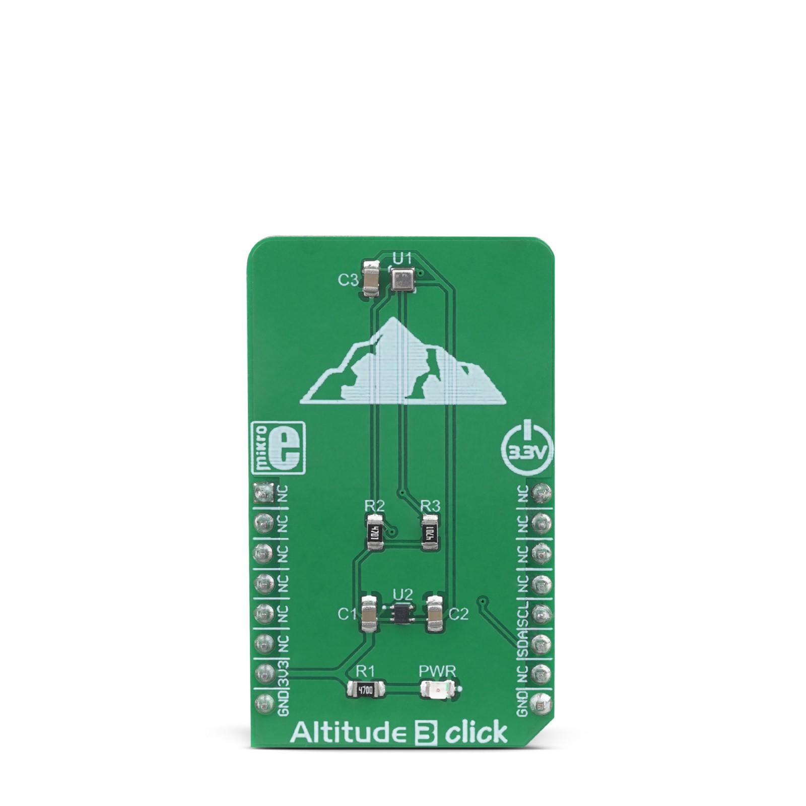
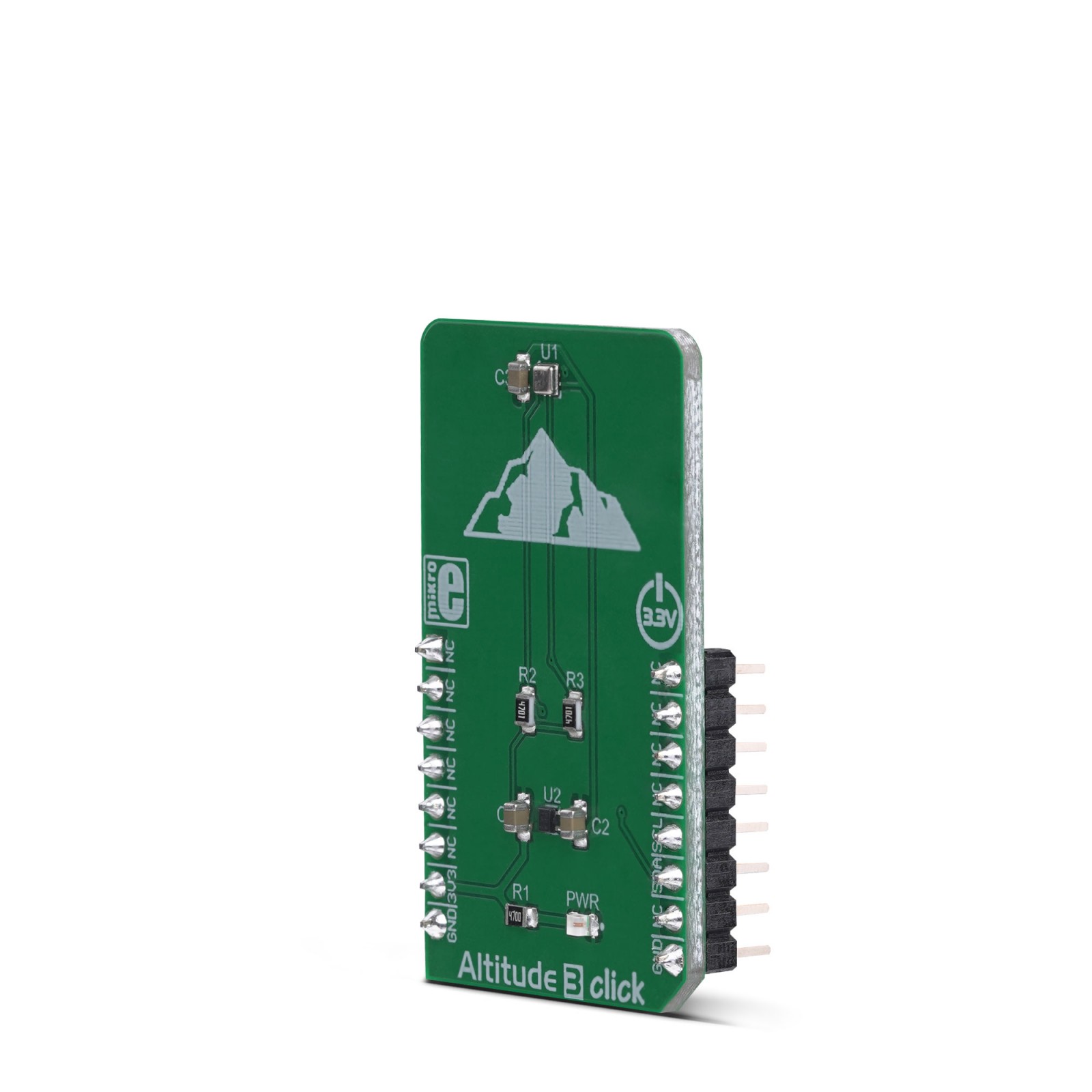
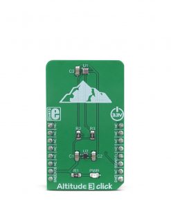
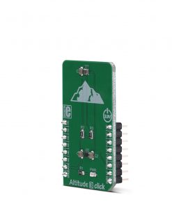
Altitude 3 click allows high-resolution barometric pressure measurement, by utilizing the ICP-10100, an integrated barometric pressure and temperature sensor. Based on the advanced MEMS capacitive sensing technology, it offers an industry-level accuracy and thermal stability. A very high absolute pressure accuracy up to ±1 Pa allows Altitude 3 click to sense very small altitude changes, within the magnitude of about 10 cm. The temperature sensor offers accuracy up to ±0.4°C, in the range from -40°C to 85°C. Low power requirements make it a perfect choice for various battery-operated applications.
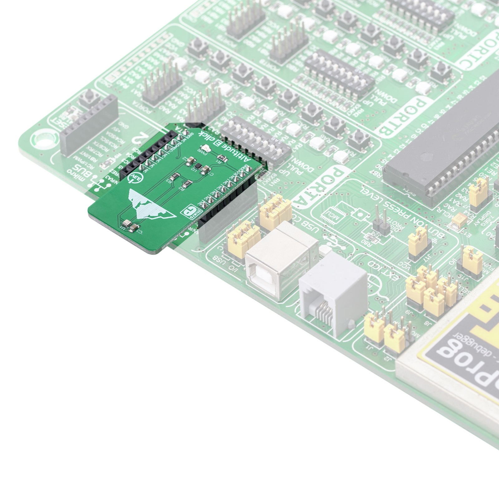
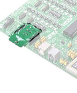
Altitude 3 click is supported by a mikroSDK compliant library, which includes functions that simplify software development. This Click board™ comes as a fully tested product, ready to be used on a system equipped with the mikroBUS™ socket.
Stock: Lead-time applicable.
| 5+ | R299.25 |
| 10+ | R283.50 |
| 15+ | R267.75 |
| 20+ | R257.67 |
Features such a very high accuracy, low power consumption, temperature stability, water resistance, and more, make Altitude 3 click a perfect choice for development of barometric pressure sensing applications for sports activity identification, mobile indoor/outdoor navigation, altitude-hold and stabilization in drones, and other similar applications that can benefit from very precise barometric pressure sensor.
How does it work?
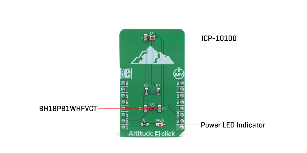
The barometric pressure sensor IC used on the Altitude 3 click is the ICP-10100, a high accuracy, low power, waterproof barometric pressure and temperature sensor IC, from TDK corporation. The sensor is manufactured using the ultra-low noise MEMS (Micro Electro Mechanical System) capacitive technology, optimized for precise altitude measurements. It can detect pressure difference with the accuracy of ±1 Pa, which translates to an altitude resolution of less than 10cm. This makes this sensor very usable in drone applications development, allowing it to hover at a fixed altitude, or to be used as the stabilization control. Also, this sensor has a very low temperature offset of only ±0.5 Pa/°C, within the range from 25°C to 45°C.
Each sensor IC is factory calibrated and the calibration parameters are stored within the OTP memory. To convert the readings into temperature and pressure values, these coefficients need to be used. The datasheet of the ICP-10100 offers formulas for these calculations. However, Altitude 3 click comes with a library that contains functions that encapsulate these calculations, which greatly accelerates application development.
Being packaged in a waterproof casing, the ICP-10100 sensor allows it to be used under 1.5m of water for the duration of 30 minutes. However, since the Click board™ itself is not waterproof, the sensor still offers a good resistance against increased humidity and moisture. The ICP-10100 sensor offers the best performance when operated within the normal pressure and temperature conditions within the range from 0°C to 45°C, and from 95 kPa to 105 kPa.
The ICP-10100 can be operated in four different modes, allowing its performace to be tailored according to specific requirements. These modes allow a compromise between high precision, low noise, output speed, and power consumption. These modes include Low Power mode (LP), Normal mode (N), Low Noise mode (LN) and Ultra Low Noise mode (ULN). The datasheet of the ICP-10100 contains a table that displays the conversion time, current consumption, and pressure measurement noise for each of these modes, allowing the optimal mode to be chosen.
This Click board™ uses the I2C protocol to communicate with the host MCU. It contains two pull-up resistors for each of the I2C lines. The ICP-10100 is operated with only 1.8V. To provide this voltage, an additional IC had to be used. The BH18PB1WHFVCT is a small LDO regulator, providing the required voltage for the ICP-10100. Both I2C lines of the pressure sensor IC are pulled up to a 3.3V power rail though, allowing it to be operated by most MCUs that typically use 3.3V logic voltage levels. Please note that the Click board™ supports only 3.3V MCUs and it is not intended to be controlled with MCUs that use 5V without a proper level shifting circuitry.
Specifications
Type
Altitude,Pressure
Applications
It is a perfect choice for development of barometric pressure sensing applications for sports activity identification, mobile indoor/outdoor navigation, altitude-hold in drones, and other similar applications that can benefit from a precise barometric pressure sensor
On-board modules
ICP-10100, a high accuracy, low power, waterproof barometric pressure and temperature sensor IC, from TDK corporation
Key Features
Low power consumption, high measurement accuracy, factory calibrated compensation coefficients, high repeatability of the measurement data, water and moisture resistance, and more
Interface
I2C
Feature
No ClickID
Compatibility
mikroBUS™
Click board size
M (42.9 x 25.4 mm)
Input Voltage
3.3V
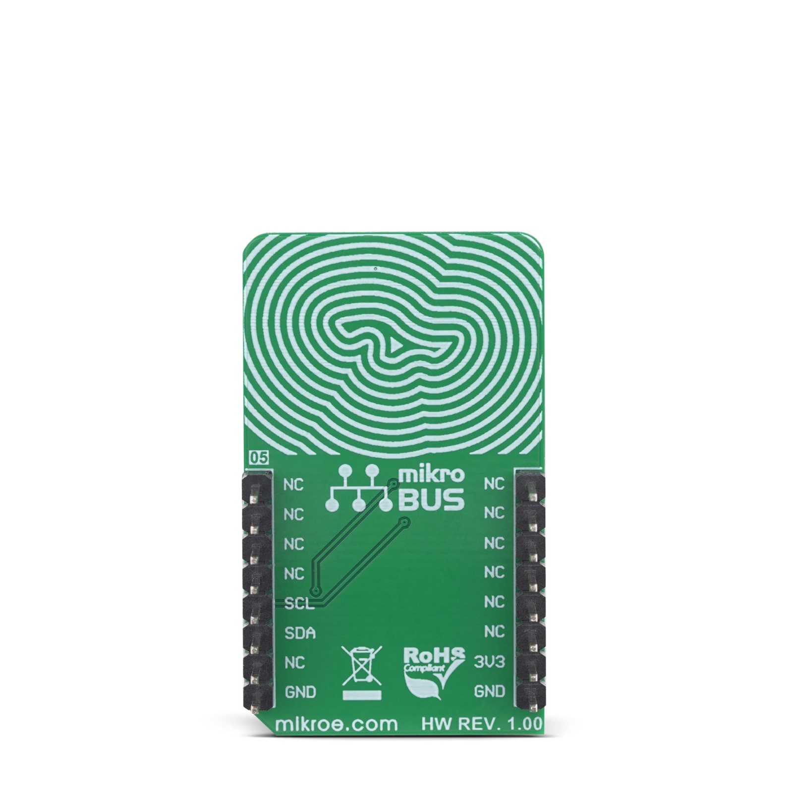
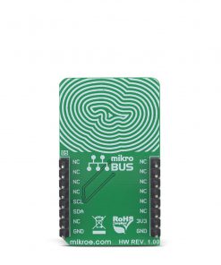
Pinout diagram
This table shows how the pinout on Altitude 3 Click corresponds to the pinout on the mikroBUS™ socket (the latter shown in the two middle columns).
Altitude 3 click electrical specifications
| Description | Min | Typ | Max | Unit |
|---|---|---|---|---|
| Pressure range (extended/maximum) | 30 (25) | – | 110 (115) | kPa |
| Pressure measurement resolution | – | 0.01 | Pa | |
| Absolute pressure accuracy (normal/extended range) | -1 (-1.5) | – | 1 (1.5) | Pa |
| Temperature range | -40 | – | 85 | ˚C |
| Temperature accuracy | -0.4 | – | 0.4 | ˚C |
Onboard settings and indicators
| Label | Name | Default | Description |
|---|---|---|---|
| LD1 | PWR | – | Power LED indicator |
Software support
We provide a library for the Altitude 3 Click on our LibStock page, as well as a demo application (example), developed using MikroElektronika compilers. The demo can run on all the main MikroElektronika development boards.
Library Description
The library performs a control of the Altitude 3 Click board. This library can read a calibration data from OTP sensor, also a temperature and pressure results of AD conversion. The all converted results can be calculated to standard units, and depending on the temperature and pressure data the library can calculate altitude. For more details check documentation.
Key functions:
T_ALTITUDE3_RETVAL altitude3_measurementMode( uint16_t modeCmd )– Function sends a command which selects a measurement mode and data reading order.void altitude3_init( T_altitude3_param *s )– Function sends a command to read calibration data from OTP sensor and other initialization data, which is necessary for calculations.T_ALTITUDE3_RETVAL altitude3_getData( uint8_t read_order, int8_t *temperature, uint16_t *pressure, int16_t *altitude )– Function performs a calibration data reading, only once, and then reads a temperature and pressure data and calculates these values to standard units. Also calculates the altitude depending on the temperature and pressure data.
Examples description
The application is composed of the three sections :
- System Initialization – Initializes peripherals and pins.
- Application Initialization – Initializes I2C interface and performs a SW Reset of the device.
- Application Task – (code snippet) – Selects the desired measurement mode and data reading order, and after that calculates the temperature, pressure and altitude data to standard units and shows results to uart terminal.
void applicationTask()
{
    response = altitude3_measurementMode( _ALTITUDE3_NORMAL_T_FIRST );

    response = altitude3_getData( response, &_temperature, &_pressure, &_altitude );

    if (response == _ALTITUDE3_OK)
    {
        ShortToStr( _temperature, text );
        mikrobus_logWrite( "Temperature is : ", _LOG_TEXT );
        mikrobus_logWrite( text, _LOG_TEXT );
        logUnit();

        WordToStr( _pressure, text );
        mikrobus_logWrite( "Pressure is : ", _LOG_TEXT );
        mikrobus_logWrite( text, _LOG_TEXT );
        mikrobus_logWrite( " mbar[hPa]", _LOG_LINE );

        IntToStr( _altitude, text );
        mikrobus_logWrite( "Altitude is : ", _LOG_TEXT );
        mikrobus_logWrite( text, _LOG_TEXT );
        mikrobus_logWrite( " m", _LOG_LINE );
        mikrobus_logWrite( "", _LOG_LINE );

        Delay_ms( 400 );
    }
}
Additional Functions :
- logUnit – Shows Celsius degrees symbol to uart terminal.
The full application code, and ready to use projects can be found on our LibStock page.
Other mikroE Libraries used in the example:
ConversionsI2CUART
Additional notes and informations
Depending on the development board you are using, you may need USB UART click, USB UART 2 click or RS232 click to connect to your PC, for development systems with no UART to USB interface available on the board. The terminal available in all MikroElektronika compilers, or any other terminal application of your choice, can be used to read the message.
Resources
Downloads
| Weight | 18 g |
|---|---|
| Brand | MikroElektronika |

