Diff Press Click
R1,050.00 ex. VAT
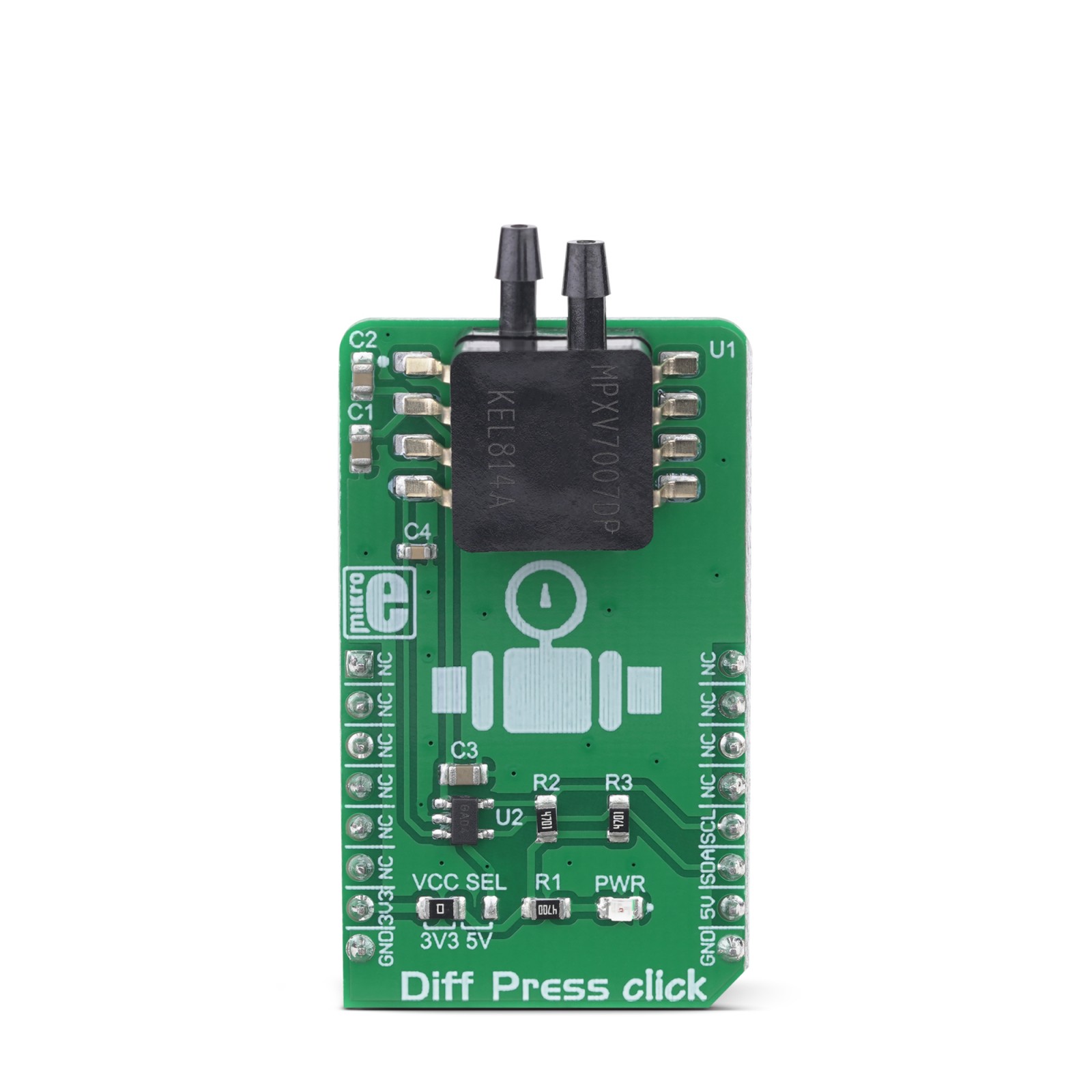
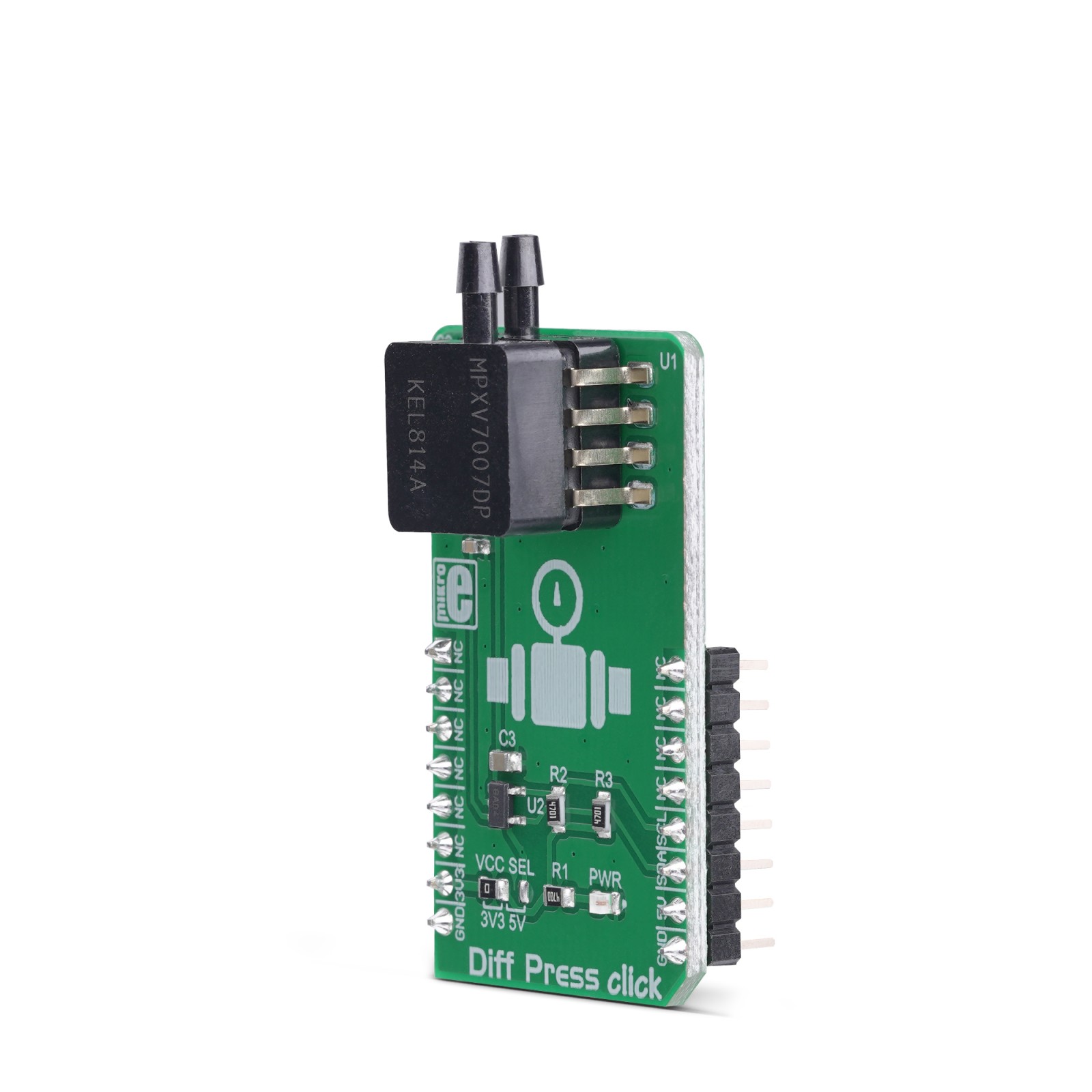
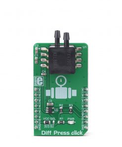
Diff Press Click is an accurate pressure sensor Click board™ capable of measuring differential pressure. This Click board™ utilizes a very precise differential pressure sensor from NXP, labeled as MPXV7007DP. This piezo-resistive transducer is an advanced monolithic pressure sensor, combining advanced MEMS manufacturing technologies with on-chip signal processing, providing accurate measurement with very low drift over temperature. The sensor outputs an analog voltage, linearly dependent on the applied pressure. This voltage is digitized by an accurate A/D converter and delivered over the I2C interface.
Stock: Lead-time applicable.
| 5+ | R997.50 |
| 10+ | R945.00 |
| 15+ | R892.50 |
| 20+ | R858.90 |
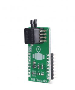
The MPXV7007DP sensor is shaped so two small tubes can be attached to it, simplifying its practical application. This makes this Click board™ an ideal solution for monitoring the pressure in different kinds of HVAC applications, hospital beds, respiratory systems, process control, and similar applications which rely on an accurate and reliable pressure monitoring.
How does it work?
Diff Press click utilizes a highly advanced, integrated monolithic differential pressure sensor, labeled as MPXV7007DP, from NXP. This sensor features piezo-resistive MEMS sensing element, combined with the integrated electronic components that allow it to achieve a high degree of linearity, as well a very low drift over temperature. It can be used to measure the differential pressure within the range of ±7kPa. The casing of the sensor contains two small tubes referred to as “ports” in the datasheet. They can be used to easily interface the sensor with various components which produce gas pressure, preventing leakage that might appear if the sealing is not good enough. The sensor is guaranteed to operate according to specifications only if used in dry air conditions. Please refer to the datasheet of the MPXV7007DP for more details.
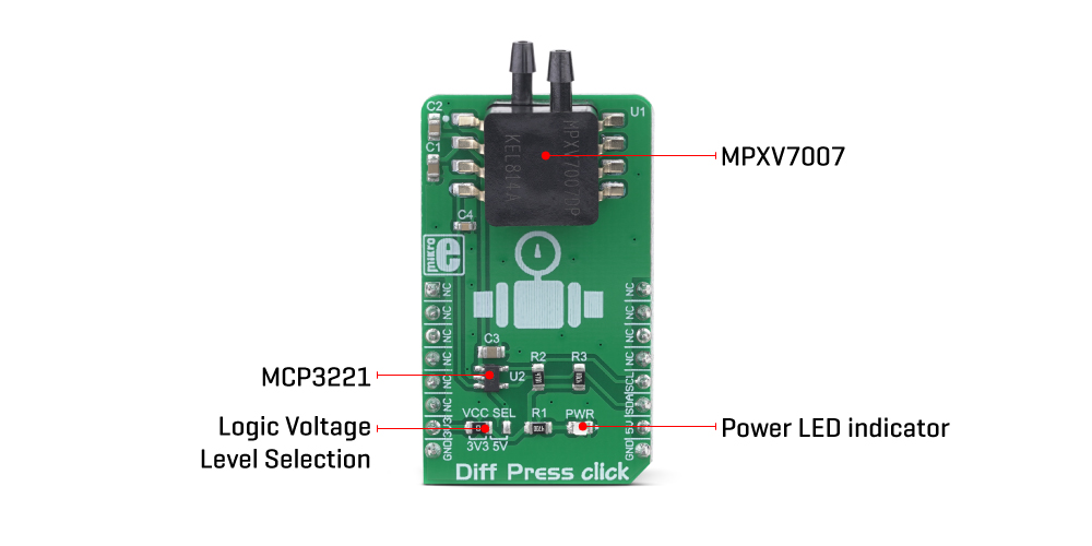
The MPXV7007DP sensor has two ports in a form of two tubes for simplified attachment to a pressurized system, as already discussed. One of these ports is designated as the Pressure side, while the other one is designated as the Vacuum side. The Pressure side is protected by a fluoro-silicone gel which protects the die from harsh media. However, the sensor is designed to be used with both positive and negative differential pressure values, depending on the application requirements (P1 > P2 or P2 > P1).
The sensor outputs half the maximum output voltage when there is no pressure difference between two input ports. As the difference increases, the voltage either decreases down to 0V (-7kPa) or increases up to its maximum value of 4.5V, typically (+7kPa). The internal calibration and a signal conditioning circuit ensure that the output voltage changes linearly with the pressure difference. The MPXV7007DP datasheet offers a graphic diagram, displaying the output voltage in respect to the pressure difference. Besides the diagram, the datasheet also offers the transfer function for the sensor output voltage, in a form of an equation. All the parameters can be found within the datasheet, if a precise calculation of the pressure is required.
Besides the MPXV7007DP, Diff Press click utilizes an additional IC. It uses the MCP3221, a 12-bit successive approximation A/D converter (ADC) with I2C Interface, from Microchip. It is used to sample the output voltage from the sensor, providing data for the microcontroller (MCU) or some other device capable of communicating over the I2C bus. The voltage is sampled to a 12-bit value using the 5V mikroBUS™ rail as the voltage reference. The relation between the ADC value and the voltage on the output pin is given by the formula: VOUT = 5/4096 x VAL
Where VOUT is the output voltage of the sensor and VAL is the 12-bit ADC value. However, the Click board™ is supplied with the mikroSDK library which contains functions for data conversion, providing readings in physical units.
Two resistors are used to pull up I2C bus lines. An onboard jumper labeled as VCC SEL offers selection of the I2C communication voltage level by connecting these resistors either with 3.3V or 5V mikroBUS™ rail. This jumper can be used to interface the Click board™ with both 3.3V and 5V MCUs, allowing a wide range of different MCUs to be used with the Click board™.
Specifications
Type
Pressure
Applications
It is an ideal solution for monitoring the pressure in different kinds of HVAC applications, hospital beds, respiratory systems, process control, and similar applications which rely on an accurate and reliable pressure monitoring.
On-board modules
MPXV7007DP, an integrated monolithic differential pressure sensor, from NXP; MCP3221, a 12bit D/A converter with I2C Interface, from Microchip
Key Features
High measurement accuracy, low drift over temperature, specially designed inlet ports for simplified use, very linear measurement readings available in 12-bit format over the I2C interface, etc.
Interface
I2C
Feature
No ClickID
Compatibility
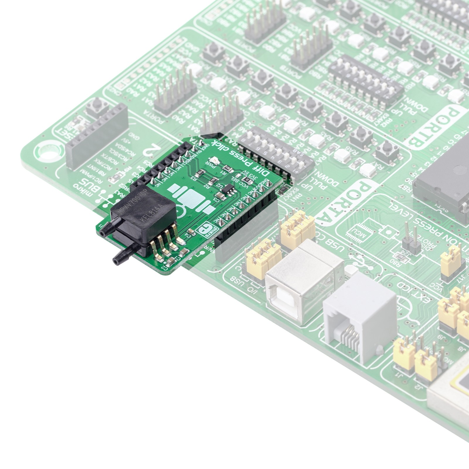
mikroBUS™
Click board size
M (42.9 x 25.4 mm)
Input Voltage
3.3V or 5V
Pinout diagram
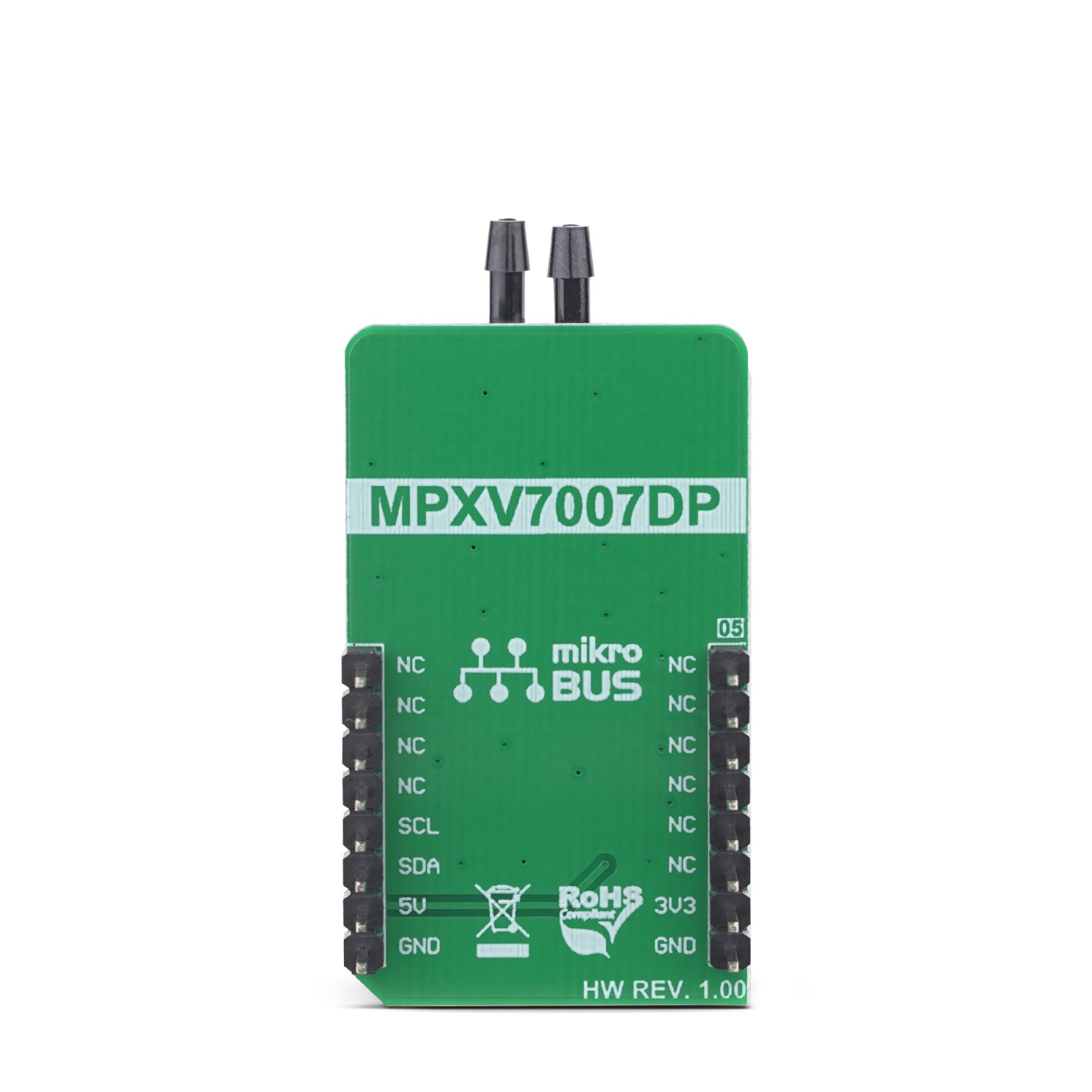
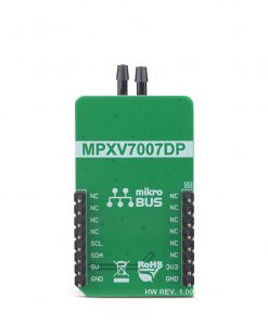
This table shows how the pinout on Diff Press Click corresponds to the pinout on the mikroBUS™ socket (the latter shown in the two middle columns).
Onboard settings and indicators
| Label | Name | Default | Description |
|---|---|---|---|
| LD1 | PWR | – | Power LED indicator |
| JP2 | VCC SEL | Left | Logic voltage level selection: left position 3.3V, right position 5V |
Diff Press Click additional specifications
| Description | Min | Typ | Max | Unit |
|---|---|---|---|---|
| Pressure range | -7 | – | 7 | kPa |
| Sensitivity | – | 286 | – | mV/kPa |
| Accuracy (0 ˚C to 85 ˚C) | -5 | – | 5 | % |
| Warm-up time | – | 20 | – | ms |
| Operating temperature range | -40 | – | 125 | ˚C |
Software support
We provide a library for the Diff Press Click on our LibStock page, as well as a demo application (example), developed using MikroElektronika compilers. The demo can run on all the main MikroElektronika development boards.
Library Description
The library contains a function for setting a reference output voltage which can be 1030mV, 2046mv, 3070mV or 4096mV.
Key functions:
uint16_t diffpress_getAdcData( void )- reads raw ADC data from devicefloat diffpress_getPressureDifference( void )- calculates pressure difference from raw ADC data
Examples description
The application is composed of the three sections :
- System Initialization – Initializes LOG and I2C
- Application Initialization – Initializes I2C driver
- Application Task – Logs pressure difference
void applicationTask( )
{
    pressureDifference = diffpress_getPressureDifference( );

    FloatToStr( pressureDifference, text );

    mikrobus_logWrite( "pressure difference : ", _LOG_TEXT );
    mikrobus_logWrite( text, _LOG_TEXT );
    mikrobus_logWrite( " kPa", _LOG_LINE );

    Delay_ms(100);
}
The full application code, and ready to use projects can be found on our LibStock page.
Other mikroE Libraries used in the example:
I2CUARTConversions
Additional notes and information
Depending on the development board you are using, you may need USB UART click, USB UART 2 click or RS232 click to connect to your PC, for development systems with no UART to USB interface available on the board. The terminal available in all MikroElektronika compilers, or any other terminal application of your choice, can be used to read the message.
Resources
Downloads
| Weight | 20 g |
|---|---|
| Brand | MikroElektronika |

