SAML Touch Click
R315.00 ex. VAT
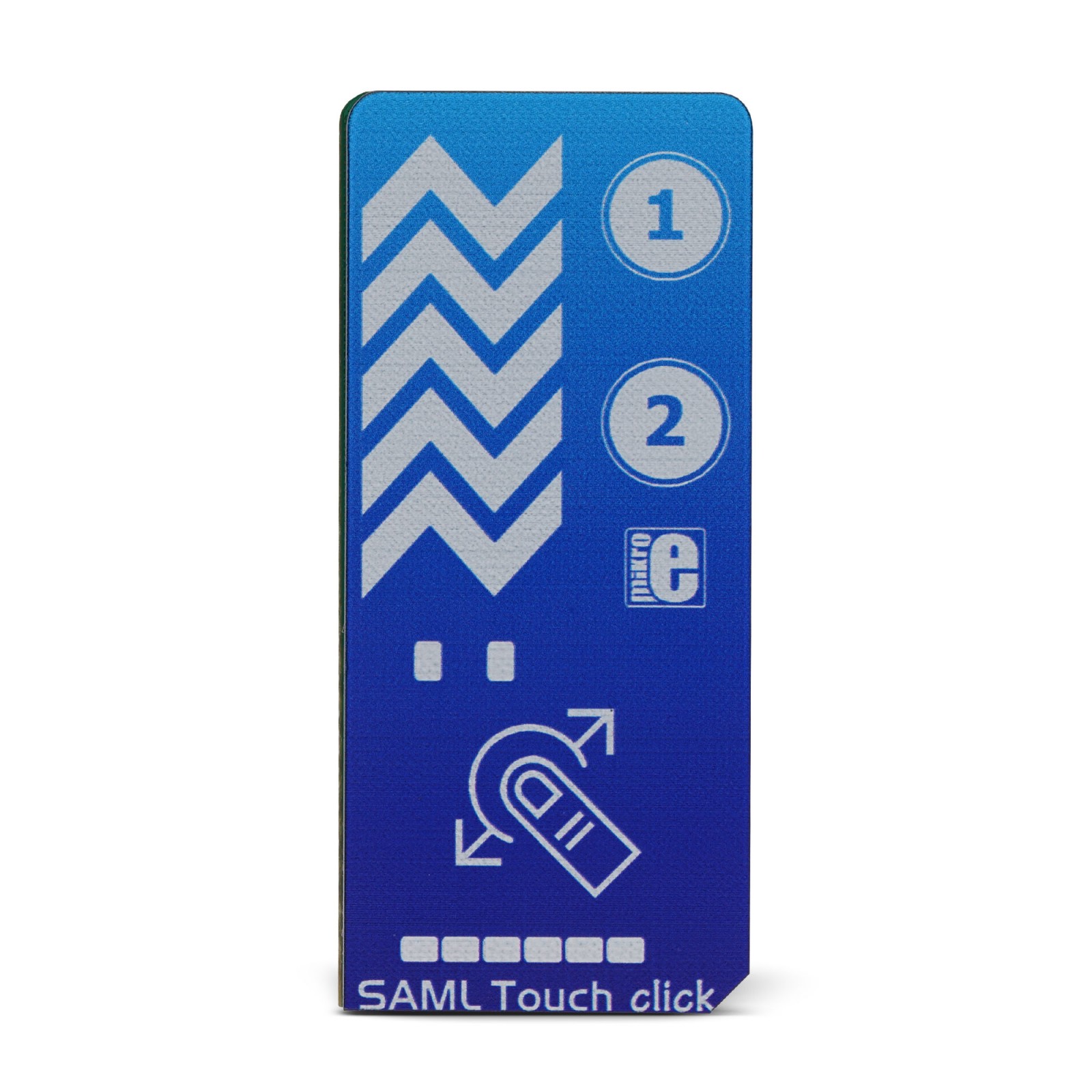
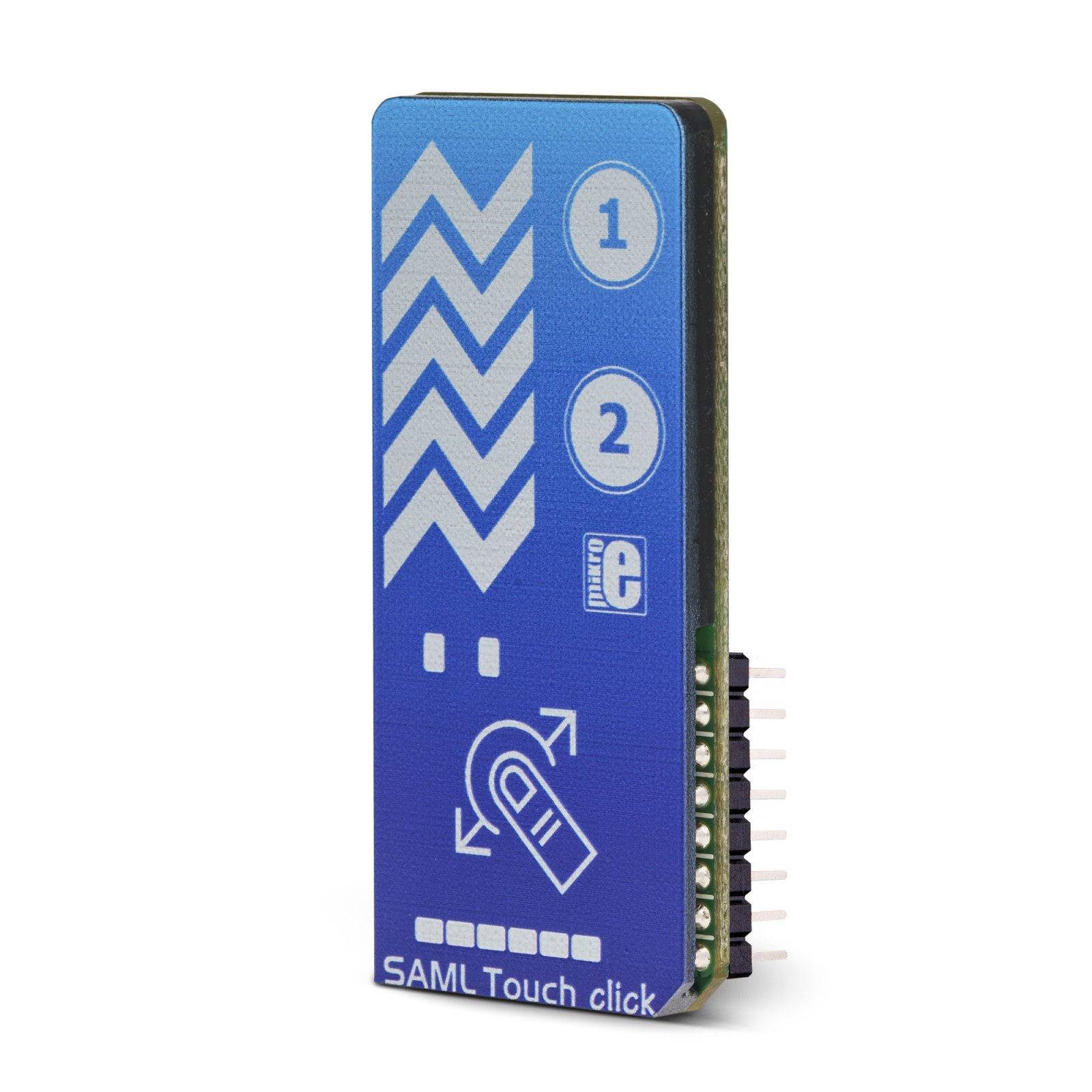
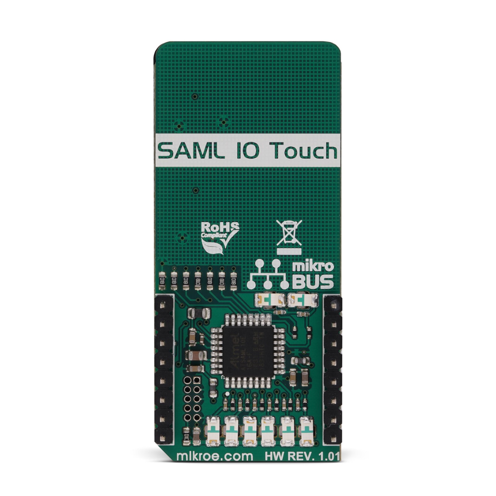
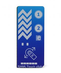
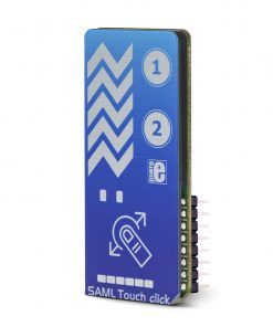
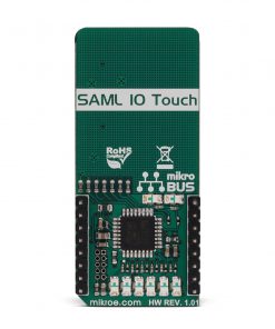
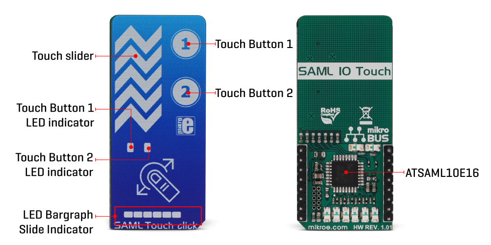
SAML Touch Click is a Click board™ equipped with two capacitive touch pads and one capacitive slider. There are also LED indicators, which are used to indicate touch evens for each of the available touch components: two LEDs (one for each touchpad), and one six-segment bargraph, used to indicate touch position across the slider. SAML click is based on the ATSAML10 MCU, an ultra-low power 32-bit ARM® Cortex® MCU, equipped with the Peripheral Touch Controller (PTC), perfectly suited for realization of various types of touch applications with superior water tolerance, excellent noise immunity & responsiveness. Supported by a cleverly designed firmware, it provides the complete touch controller on a Click board™.
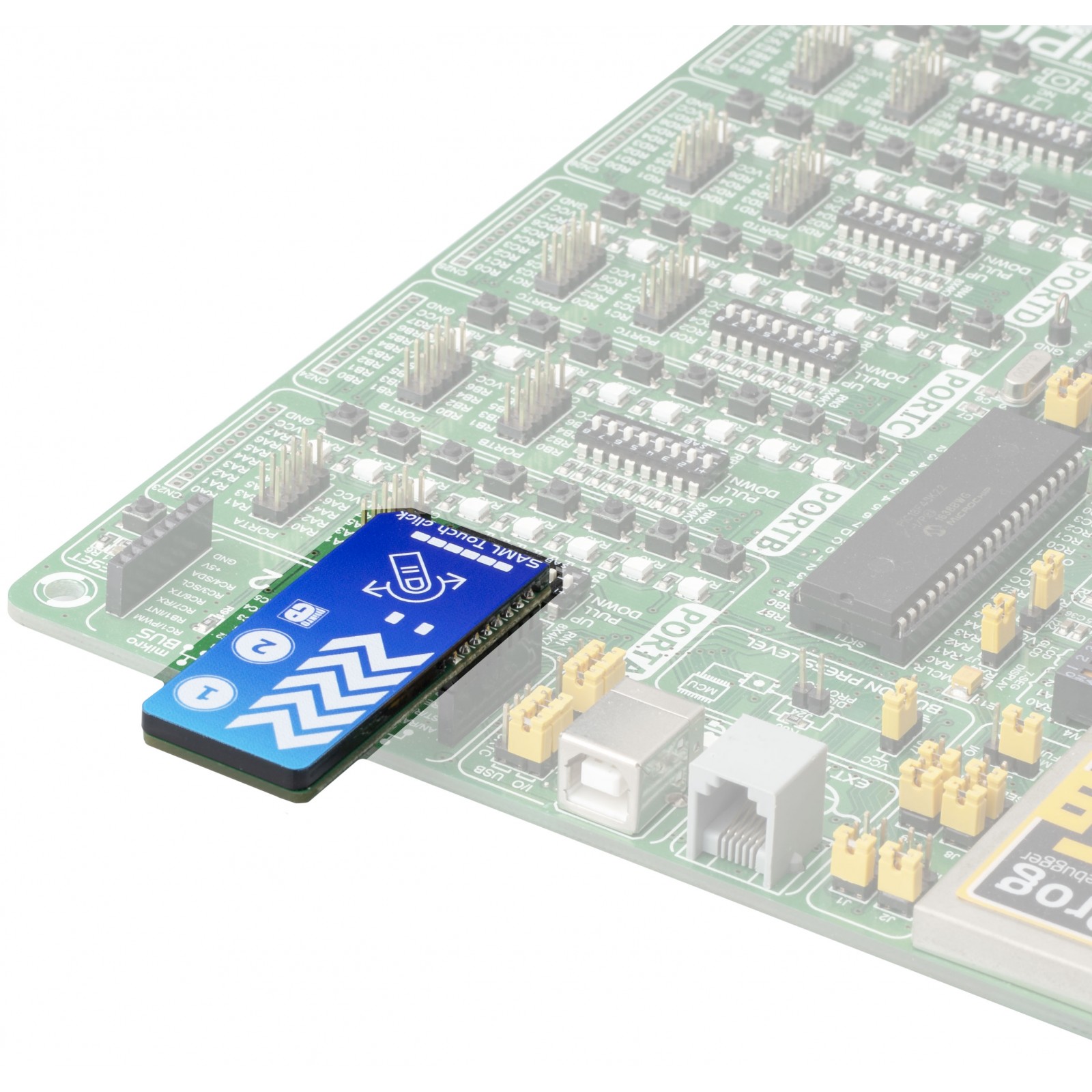
SAML click is supported by a mikroSDK compliant library, which includes functions that simplify software development. This Click board™ comes as a fully tested product, ready to be used on a system equipped with the mikroBUS™ socket.
Stock: Lead-time applicable.
| 5+ | R299.25 |
| 10+ | R283.50 |
| 15+ | R267.75 |
| 20+ | R257.67 |
SAML click is a perfect example of how simple the implementation of the Q-Touch® technology from Microchip can be. Besides the ATSAML10 MCU itself, the Click board™ contains a few additional hardware components. Thanks to the highly integrated PTC module supported by the Q-Touch®, development of complex touch applications becomes extremely simple and fast. Featuring many inherited benefits compared to mechanical buttons and sliders, this Click board™ can be used for the development of various HMI interfaces, touch-operated control panels, interfaces used in very harsh and humid environment, etc.
How does it work?
The main component of SAML click is the ATSAML10, an ultra-low power 32-bit ARM® Cortex® MicroController Unit (MCU) from Microchip. Among many other features, this MCU is contains the enhanced Peripheral Touch Controller (PTC) module, making it a perfect solution for various capacitive touch-based applications that require superior noise immunity. One of the key features of the PTC module is its ability to reliably sense touch events, even when covered with water. SAML click demonstrates the overall hardware simplicity of one such application: capacitive pads are directly connected to the MCU pins, with no additional components required. Everything is already integrated within the PTC module of the ATSAML10 MCU itself, allowing very fast development. The only passive components on this click are the resistors that limit the current through the LEDs, and accompanying filtering capacitors.
As mentioned before, the enhanced PTC module provides many benefits over similar solutions. The most distinctive it its parallel acquisition capability, allowing it to process all the inputs in parallel and simultaneous detection of multiple touch events. This increases the responsiveness of the touch interface, compared to traditional sequential acquisition circuits. It also provides better noise immunity and more robustness when used in harsh and humid environment. This allows the Click board™ to use an acrylic overlay, and still detects touch events with perfect accuracy.
Another feature of the enhanced PTC module is the Driven Shield Plus capability. This capability adds another layer of noise protection to the application. It allows touch sensors to work while exposed to moisture, sweat, rain, and even running water. Any of the capacitive touch channels can be used as a driven shield channel, offering IP-68 compliant protection.
A cleverly designed firmware is responsible for events detection, visual feedback over LED indicators, and for the communication with the host MCU. The MCU firmware is written using Q-Touch® libraries from Microchip, which offer full support for PTC modules. The communication with the ATSAML10 is realized over the UART interface. A set of UART command strings are available for the touch detection, as well as for the touch slider position. However, the Click board™ is supported by a mikroSDK compatible library, offering simple functions, saving the developer to write UART command parsers. These functions allow faster development and simplified software design.
The Click board™ is designed to work with 3.3V only. If interfacing with systems that use 5V for their operation, an appropriate level translating circuitry has to be used.
Specifications
Type
Capacitive
Applications
Featuring many inherited benefits compared to mechanical buttons and sliders, this Click board™ can be used for the development of various HMI interfaces, touch-operated control panels, interfaces used in very harsh and humid environment, etc.
On-board modules
ATSAML10, a powerful, low-power, 32-bit ARM® Cortex® Micro Controller Unit (MCU) by Microchip.
Key Features
ATSAML10 onboard, a powerful MCU with the Integrated PTC capacitive touch peripheral module, parallel acquisition greatly improves responsiveness, Driven Shield Plus feature offers immunity to using the Click board™ in humid conditions, clean and visually appealing indication of the touch over LEDs, two buttons plus one slider, etc.
Interface
UART
Feature
No ClickID
Compatibility
mikroBUS™
Click board size
L (57.15 x 25.4 mm)
Input Voltage
3.3V
Pinout diagram
This table shows how the pinout on SAML Touch Click corresponds to the pinout on the mikroBUS™ socket (the latter shown in the two middle columns).
Onboard settings and indicators
| Label | Name | Default | Description |
|---|---|---|---|
| LD1 – LD6 | – | – | Capacitive slide bargraph indicator |
| LD7 | – | – | Touch button 1 LED indicator |
| LD8 | – | – | Touch button 2 LED indicator |
Software support
We provide a library for the SAML Touch Click on our LibStock page, as well as a demo application (example), developed using MikroElektronika compilers. The demo can run on all the main MikroElektronika development boards.
Library Description
The library contains the function which parses the response received by the module, and checks the buttons and slider.
Key functions:
void samltouch_parser(char *dataIn, samltouch_state_T *state)– The function parses the response it receives
Examples description
The application is composed of the three sections :
- System Initialization – Initializes UART used for the communcation with SAML Touch module and UART used for infromation logging.
- Application Initialization – Initializes driver init and timer init.
- Application Task – running in parallel core state machine. Check that the button 1 or button 2 or the active slider is pressed. If it detects that the buttons 1 or 2 are pressed, it logs a button detection message. If it detects that the slider is active, it logs a message that the slider is active and its current position is 0-255.
void applicationTask()
{
// CORE STATE MACHINE
    samltouch_process();

    if(timerCounter > 100)
    {
        if(SAML_Touch.button2 == 1)
        {
            mikrobus_logWrite( "Button 2 is pressed.", _LOG_LINE );
        }
        else if(SAML_Touch.button1 == 1)
        {
            mikrobus_logWrite( "Button 1 is pressed.", _LOG_LINE );
        }
        timerCounter = 0;
    }

    if(SAML_Touch.sw_state == 1)
    {
        mikrobus_logWrite( "Slider is active.", _LOG_LINE );
        if(SAML_Touch.sw_pos != 0)
        {
            mikrobus_logWrite( "Slider position is  ", _LOG_TEXT );
            IntToStr(SAML_Touch.sw_pos, demoText);
            mikrobus_logWrite( demoText, _LOG_LINE );
        }
    }
}
Additional Functions :
All additional functions such as timer initialization and default handler.
The full application code, and ready to use projects can be found on our LibStock page.
Other mikroE Libraries used in the example:
StringUARTConversions
Additional notes and informations
Depending on the development board you are using, you may need USB UART click, USB UART 2 click or RS232 click to connect to your PC, for development systems with no UART to USB interface available on the board. The terminal available in all MikroElektronika compilers, or any other terminal application of your choice, can be used to read the message.
mikroSDK
This click board is supported with mikroSDK - MikroElektronika Software Development Kit. To ensure proper operation of mikroSDK compliant click board demo applications, mikroSDK should be downloaded from the LibStock and installed for the compiler you are using.
For more information about mikroSDK, visit the official page.
Resources
Downloads
| Weight | 27 g |
|---|---|
| Brand | MikroElektronika |

