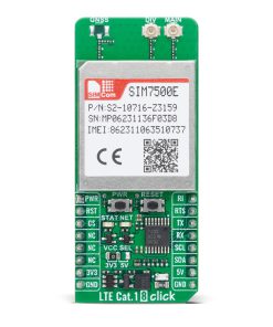


LTE Cat.1 8 Click
R2,550.00 ex. VAT
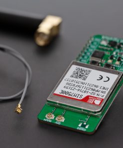
LTE Cat.1 8 Click is a compact add-on board designed to provide reliable cellular connectivity for embedded applications. This board features the SIM7500E, LTE Cat 1 module from SIMCom, supporting LTE-FDD mode with multi-band coverage for Europe. The module offers data rates of up to 10Mbps downlink and 5Mbps uplink, multi-constellation GNSS, and supports drivers for operating systems like Windows, Linux, and Android. Key features include a UART interface for communication, a USB interface, firmware upgrade functionality, and visual indicators for network and power status. This Click board™ is ideal for IoT applications such as telematics, industrial routers, remote monitoring, and diagnostics.
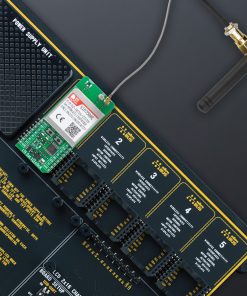
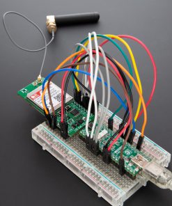
LTE Cat.1 8 Click is fully compatible with the mikroBUS™ socket and can be used on any host system supporting the mikroBUS™ standard. It comes with the mikroSDK open-source libraries, offering unparalleled flexibility for evaluation and customization. What sets this Click board™ apart is the groundbreaking ClickID feature, enabling your host system to seamlessly and automatically detect and identify this add-on board.
Stock: Lead-time applicable.
| 5+ | R2,422.50 |
| 10+ | R2,295.00 |
| 15+ | R2,167.50 |
| 20+ | R2,085.90 |
How does it work?
LTE Cat.1 8 Click is based on the SIM7500E, LTE Cat 1 module from SIMCom. This module enables LTE Category 1 communication and is capable of operating across various wireless standards including LTE-TDD, LTE-FDD, HSPA+, GSM, GPRS, and EDGE. Its compatibility with LTE, UMTS, and GSM networks ensures broad global coverage, making it ideal for applications that require dependable mobile connectivity across different regions. Its frequency band compatibility includes LTE-FDD on bands B1, B3, B7, B8, and B20, as well as GSM on 900 and 1800 MHz, enabling the device to adapt to multiple carrier networks efficiently. Designed for IoT scenarios like telematics, remote monitoring, CPE systems, industrial routers, and remote diagnostics, the LTE Cat.1 8 Click stands out as a reliable platform for developers seeking stable and versatile mobile communication in embedded systems.

With support for download speeds of up to 10Mbps and upload speeds of up to 5Mbps, the SIM7500E provides a balanced data throughput suitable for a wide range of IoT use cases. In addition to its robust cellular communication capabilities, the module also features advanced location services through integrated multi-constellation GNSS support, ensuring high-accuracy positioning using various satellite systems. The SIM7500E also comes equipped with an array of embedded network protocols, including TCP/IP, IPv4, IPv6, Multi-PDP, FTP, FTPS, HTTP, HTTPS, and DNS, providing a comprehensive solution for secure and flexible data transmission. Furthermore, it supports USB drivers across major operating systems such as Windows, Linux, and Android, allowing integration into diverse development environments.
Communication between the SIM7500E and the host MCU is made through a UART interface, using standard UART RX and TX pins and hardware flow control pins (CTS/RTS/RI – Clear to Send/Ready to Send/Ring Indicator) for data transfer. The module defaults to a communication speed of 115200bps, allowing for data exchange over AT commands. This Click board™ also includes a USB Type C connector for both power and data transfer, which is compliant with the USB 2.0 specification (peripheral only), I2C interface only for read/write register values of the I2C peripheral devices, a BOOT switch on the back of the board to manage firmware upgrades (0 for normal operation, 1 for USB download), and FLIGHT switch for switching the board between Normal (1) and Flight (0) operation mode.
The LTE Cat.1 8 Click includes several additional functionalities that enhance its usability and control. The PWR button allows users to easily power the module ON or OFF, while the RESET button provides a quick way to reset the module. These functions can also be controlled digitally via the mikroBUS™ pins PWR and RST, offering greater flexibility. Moreover, these controls have dedicated test points for easier debugging and testing. The board also features some visual indicators to provide real-time status updates.
The first red NET LED indicates the module’s current network status. When the LED is always on, the device searches for a network. A faster blinking pattern (200ms ON/OFF) indicates data transmission or 4G network registration. If the LED blinks slowly with an 800ms ON/OFF pattern, the module is registered on a 2G or 3G network. When the LED is OFF, the device is powered OFF or sleep mode. The second yellow STAT LED indicates the module’s power status, which stays off when the module is OFF and turns ON when the module is powered on.
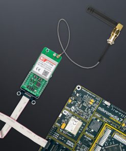
The board features three u.Fl connectors for LTE, Auxiliary-diversity, and optional GNSS antennas that MIKROE offers, like the GSM/GPRS antenna combined with an IPEX-SMA cable for flexible and efficient connectivity options. In addition, the user can easily choose the power supply of the optional GNSS antenna by choosing between 3.3V and 5V on the GNSS ANT jumper. However, please note that GNSS functionality is not currently supported on this Click board™, and as a result, GNSS-related components are not soldered. The board is equipped with a micro SIM card holder that supports both 1.8V and 3.0V uSIM cards, ensuring compatibility with a wide range of cellular networks and allowing users to select the most appropriate service provider for their particular use case.
This Click board™ can operate with both 3.3V and 5V logic voltage levels selected via the VCC SEL jumper. Since the SIM7500E module operates at 3.8V, logic-level translators, the TXB0106 and PCA9306, are also used for proper operation and an accurate signal-level translation. This way, both 3.3V and 5V capable MCUs can use the communication lines properly. Also, this Click board™ comes equipped with a library containing easy-to-use functions and an example code that can be used as a reference for further development.
Specifications
Type
4G LTE,GSM/LTE
Applications
Ideal for IoT applications such as telematics, industrial routers, remote monitoring, and diagnostics
On-board modules
SIM7500E – LTE Cat 1 module from SIMCom
Key Features
LTE Cat.1 connectivity, support for LTE-FDD/HSPA+/GSM networks, multi-constellation GNSS support, UART and USB interfaces, I2C interface for peripheral access, firmware upgrade, network and power status LEDs, three u.Fl antenna connectors for LTE, diversity, and GNSS, micro SIM card holder supporting 1.8V and 3.0V uSIMs, mikroSDK-compatible software library with example code, and more
Interface
I2C,UART,USB
Feature
ClickID
Compatibility
mikroBUS™
Click board size
L (57.15 x 25.4 mm)
Input Voltage
3.3V or 5V
Pinout diagram
This table shows how the pinout on LTE Cat.1 8 Click corresponds to the pinout on the mikroBUS™ socket (the latter shown in the two middle columns).
| Notes | Pin | Pin | Notes | ||||
|---|---|---|---|---|---|---|---|
| Module Power-ON | PWR | 1 | AN | PWM | 16 | RI | Ring Indicator |
| Reset / ID SEL | RST | 2 | RST | INT | 15 | RTS | UART RTS |
| UART CTS / ID COMM | CS | 3 | CS | RX | 14 | TX | UART TX |
| NC | 4 | SCK | TX | 13 | RX | UART RX | |
| NC | 5 | MISO | SCL | 12 | SCL | I2C Clock | |
| NC | 6 | MOSI | SDA | 11 | SDA | I2C Data | |
| Power Supply | 3.3V | 7 | 3.3V | 5V | 10 | 5V | Power Supply |
| Ground | GND | 8 | GND | GND | 9 | GND | Ground |
Onboard settings and indicators
| Label | Name | Default | Description |
|---|---|---|---|
| LD1 | PWR | – | Power LED Indicator |
| LD2 | NET | – | Network Activity Status LED Indicator |
| LD3 | STAT | – | Module Operational Status LED Indicator |
| JP1 | VCC SEL | Left | Power Voltage Level Selection 3V3/5V: Left position 3V3, Right position 5V |
| JP2 | GNSS ANT | Unsoldered | GNSS Antenna Supply Selection 3V3/5V: Left position 3V3, Right position 5V |
| T1 | RESET | – | Module Reset Button |
| T2 | PWR | – | Module Power-ON Button |
| SW1 | FLIGHT | Left | USB FW Upgrade Switch 0/1: Position 0 for Flight mode, Position 1 for Normal mode |
| SW2 | BOOT | Left | USB FW Upgrade Switch 1/0: Position 1 for USB download, Position 0 for Normal operation |
LTE Cat.1 8 Click electrical specifications
| Description | Min | Typ | Max | Unit |
|---|---|---|---|---|
| Supply Voltage | 3.3 | – | 5 | V |
| LTE Frequency Range | 758 | – | 2570 | MHz |
| LTE Output Power | – | +23 | – | dBm |
Software Support
LTE Cat.1 8 Click demo application is developed using the NECTO Studio, ensuring compatibility with mikroSDK‘s open-source libraries and tools. Designed for plug-and-play implementation and testing, the demo is fully compatible with all development, starter, and mikromedia boards featuring a mikroBUS™ socket.
Example Description
Application example shows device capability of connecting to the network and sending SMS or TCP/UDP messages using standard “AT” commands.
Key Functions
ltecat18_cfg_setupThis function initializes Click configuration structure to initial values.ltecat18_initThis function initializes all necessary pins and peripherals used for this Click board.ltecat18_set_sim_apnThis function sets APN for sim card.ltecat18_send_sms_textThis function sends text message to a phone number.ltecat18_cmd_setThis function sets a value to a specified command of the Click module.
Application Init
Initializes the driver and logger.
Application Task
Application task is split in few stages:
- LTECAT18_POWER_UP:
Powers up the device, performs a device factory reset and reads system information.
- LTECAT18_CONFIG_CONNECTION:
Sets configuration to device to be able to connect to the network.
- LTECAT18_CHECK_CONNECTION:
Waits for the network registration indicated via CREG command and then checks the signal quality report.
- LTECAT18_CONFIG_EXAMPLE:
Configures device for the selected example.
- LTECAT18_EXAMPLE:
Depending on the selected demo example, it sends an SMS message (in PDU or TXT mode) or TCP/UDP message. By default, the TCP/UDP example is selected.
Application Output
This Click board can be interfaced and monitored in two ways:
- Application Output – Use the “Application Output” window in Debug mode for real-time data monitoring. Set it up properly by following this tutorial.
- UART Terminal – Monitor data via the UART Terminal using a USB to UART converter. For detailed instructions, check out this tutorial.
Additional Notes and Information
The complete application code and a ready-to-use project are available through the NECTO Studio Package Manager for direct installation in the NECTO Studio. The application code can also be found on the MIKROE GitHub account.
Resources
Downloads
| Weight | 24 g |
|---|---|
| Brand | MikroElektronika |