Opto Encoder 6 Click
R235.00 ex. VAT
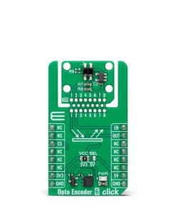
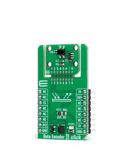
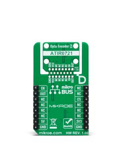
Opto Encoder 6 Click is a compact add-on board for precise motion and position detection. This board features the ATIR0721DS, a transmissive photointerrupter from Kingbright, ensuring high sensitivity and reliable performance. This slotted optical switch detects object movement by interrupting the light beam, with a visible light cut-off design to minimize ambient light interference. Additionally, it integrates the MAX40200 from Analog Devices, which enables or disables the photointerrupter through the EN pin, optimizing power efficiency and operational flexibility, and a Click Snap feature for flexible implementation. The output signal is accessible via the OUT pin, allowing its integration into various control and monitoring systems. Opto Encoder 6 Click is ideal for applications like motor speed monitoring, position tracking in automation systems, and other industrial and consumer electronics requiring precise motion sensing.
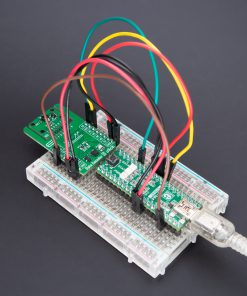
Opto Encoder 6 Click is fully compatible with the mikroBUS™ socket and can be used on any host system supporting the mikroBUS™ standard. It comes with the mikroSDK open-source libraries, offering unparalleled flexibility for evaluation and customization. What sets this Click board™ apart is the groundbreaking ClickID feature, enabling your host system to seamlessly and automatically detect and identify this add-on board, alongside a Click Snap feature introducing a new level of flexibility and ease of use.
Stock: Lead-time applicable.
| 5+ | R223.25 |
| 10+ | R211.50 |
| 15+ | R199.75 |
| 20+ | R192.23 |
How does it work?
Opto Encoder 6 Click is based on the ATIR0721DS, a transmissive photointerrupter from Kingbright, designed to offer high sensitivity and reliable performance, making it well-suited for various microcomputerized control systems. The ATIR0721DS operates as a slotted optical switch, where an object passing through the sensing slot interrupts the light beam, generating a precise output signal. Additionally, the device is designed as a visible light cut-off type, ensuring enhanced immunity to ambient light interference and providing a stable detection mechanism in different lighting conditions. Thanks to its compact design, the Opto Encoder 6 Click is an excellent choice for implementations where space-saving and reliable detection are crucial.

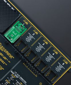
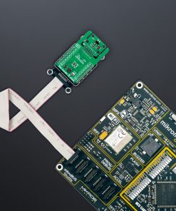
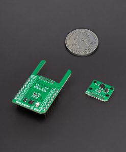
This Click board™ is designed in a unique format supporting the newly introduced MIKROE feature called “Click Snap.” Unlike the standardized version of Click boards, this feature allows the main sensor area to become movable by breaking the PCB, opening up many new possibilities for implementation. Thanks to the Snap feature, the ATIR0721DS can operate autonomously by accessing its signals directly on the pins marked 1-8. Additionally, the Snap part includes a specified and fixed screw hole position, enabling users to secure the Snap board in their desired location.
To manage the operation of the ATIR0721DS photointerrupter, Opto Encoder 6 Click integrates the MAX40200 from Analog Devices that enables or disables the photointerrupter through the EN pin. This setup allows precise control over the photointerrupter’s functionality, optimizing power efficiency and operational flexibility. The output signal from the photointerrupter is available via the OUT pin on the board, allowing integration into various applications that require motion or position tracking.
This Click board™ can operate with either 3.3V or 5V logic voltage levels selected via the VCC SEL jumper. This way, both 3.3V and 5V capable MCUs can use the communication lines properly. Also, this Click board™ comes equipped with a library containing easy-to-use functions and an example code that can be used as a reference for further development.
Click Snap
Click Snap is an innovative feature of our standardized Click add-on boards, introducing a new level of flexibility and ease of use. This feature allows for easy detachment of the main sensor area by simply snapping the PCB along designated lines, enabling various implementation possibilities. For detailed information about Click Snap, please visit the official page dedicated to this feature.
Specifications
Type
Optical
Applications
Ideal for applications like motor speed monitoring, position tracking in automation systems, and various microcomputerized control systems
On-board modules
ATIR0721DS – transmissive photointerrupter from Kingbright
Key Features
Slotted optical switch for precise motion detection, visible light cut-off design for enhanced ambient light immunity, high sensitivity, Click Snap feature, and more
Interface
GPIO
Feature
Click Snap,ClickID
Compatibility
mikroBUS™
Click board size
M (42.9 x 25.4 mm)
Input Voltage
3.3V or 5V
Pinout diagram
This table shows how the pinout on Opto Encoder 6 Click corresponds to the pinout on the mikroBUS™ socket (the latter shown in the two middle columns).
| Notes | Pin | Pin | Notes | ||||
|---|---|---|---|---|---|---|---|
| NC | 1 | AN | PWM | 16 | EN | Photointerrupter Enable | |
| NC | 2 | RST | INT | 15 | OUT | Photointerrupter Output | |
| ID COMM | CS | 3 | CS | RX | 14 | NC | |
| NC | 4 | SCK | TX | 13 | NC | ||
| NC | 5 | MISO | SCL | 12 | NC | ||
| NC | 6 | MOSI | SDA | 11 | NC | ||
| Power Supply | 3.3V | 7 | 3.3V | 5V | 10 | 5V | Power Supply |
| Ground | GND | 8 | GND | GND | 9 | GND | Ground |
Onboard settings and indicators
| Label | Name | Default | Description |
|---|---|---|---|
| LD1 | PWR | – | Power LED Indicator |
| JP1 | VCC SEL | Left | Power Voltage Level Selection 3V3/5V: Left position 3V3, Right position 5V |
Opto Encoder 6 Click electrical specifications
| Description | Min | Typ | Max | Unit |
|---|---|---|---|---|
| Supply Voltage | 3.3 | – | 5 | V |
| Sensing Distance | – | – | 1.8 | mm |
Software Support
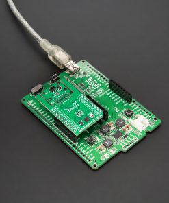
Opto Encoder 6 Click demo application is developed using the NECTO Studio, ensuring compatibility with mikroSDK‘s open-source libraries and tools. Designed for plug-and-play implementation and testing, the demo is fully compatible with all development, starter, and mikromedia boards featuring a mikroBUS™ socket.
Example Description
This example demonstrates the use of Opto Encoder 6 Click board by processing the encoder output pin state and incrementing the step counter on falling edge.
Key Functions
optoencoder6_cfg_setupThis function initializes Click configuration structure to initial values.optoencoder6_initThis function initializes all necessary pins and peripherals used for this Click board.optoencoder6_enable_outputThis function enables output by setting the EN pin to high logic state.optoencoder6_disable_outputThis function disables output by setting the EN pin to low logic state.optoencoder6_get_out_pinThis function returns the OUT pin logic state.
Application Init
Initializes the driver and logger, and enables the encoder output.
Application Task
Increments the step counter on falling edge of the encoder output pin state and displays it on the USB UART.
Application Output
This Click board can be interfaced and monitored in two ways:
- Application Output – Use the “Application Output” window in Debug mode for real-time data monitoring. Set it up properly by following this tutorial.
- UART Terminal – Monitor data via the UART Terminal using a USB to UART converter. For detailed instructions, check out this tutorial.
Additional Notes and Information
The complete application code and a ready-to-use project are available through the NECTO Studio Package Manager for direct installation in the NECTO Studio. The application code can also be found on the MIKROE GitHub account.
Resources
Downloads
| Weight | 16 g |
|---|---|
| Brand | MikroElektronika |