Boost 5 Click
R675.00 ex. VAT
Boost 5 Click is a compact add-on board that boosts voltage for battery-powered and low-power applications. This board features the MAX17250, a high-efficiency synchronous boost converter from Analog Devices, featuring True Shutdown™ and ultra-low quiescent current operation. This Click board™ supports input voltages from 2.7V to 18V and delivers regulated output voltages of 8V, 10V, 12V, or 14V, selectable via an onboard switch with peak current limit of 3.5A. It includes short-circuit protection, Pulse Frequency Modulation (PFM) for minimal power consumption, and offers flexible power sourcing through a VIN SEL jumper, allowing users to choose between an internal mikroBUS™ 5V power rail or an external supply. Boost 5 Click is ideal for battery-powered IoT devices, single or dual-cell Li-Ion battery applications, display power supplies, and buzzer/alarm drivers where reliable and efficient voltage step-up is required.
Boost 5 Click is fully compatible with the mikroBUS™ socket and can be used on any host system supporting the mikroBUS™ standard. It comes with the mikroSDK open-source libraries, offering unparalleled flexibility for evaluation and customization. What sets this Click board™ apart is the groundbreaking ClickID feature, enabling your host system to seamlessly and automatically detect and identify this add-on board.
Stock: Lead-time applicable.
| 5+ | R641.25 |
| 10+ | R607.50 |
| 15+ | R573.75 |
| 20+ | R552.15 |
How does it work?
Boost 5 Click is based on the MAX17250, a DC-DC synchronous step-up converter from Analog Devices. Designed to deliver exceptional power efficiency with minimal energy consumption, this Click board™ is ideal for battery-powered applications requiring a stable and reliable voltage boost. With its wide input voltage range, the MAX17250 steps up the voltage to as high as 14V (with peak current limit of 3.5A) while maintaining a low quiescent current operation. One of its standout features is True Shutdown™. This unique capability ensures complete disconnection of the output from the input, reducing battery drain to a mere 0.1µA in shutdown mode, significantly extending battery life in portable and low-power applications, including battery-powered IoT devices, single or dual-cell Li-Ion battery-powered systems, buzzer/alarm drivers, as well as display power supplies.

The MAX17250 operates in three operational modes to optimize performance based on the system’s requirements. At startup, the soft-start mode ensures a smooth power-up sequence, preventing inrush currents that could destabilize the system. Once operational, the converter functions using a fixed on-time and minimum off-time Pulse Frequency Modulation (PFM) architecture, which only activates the switching regulator when necessary, achieving an ultra-low typical quiescent current of just 60µA. Additionally, its integrated short-circuit protection further enhance reliability and safe operation under varying load conditions.
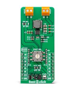
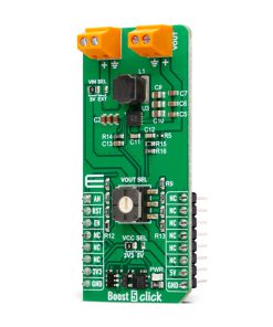
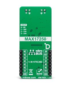
This Click board™ features a four-position switch that allows users to select the desired regulated output voltage at the VOUT terminal, providing flexibility for different application needs. The switch positions correspond to four preset voltage levels: 8V at position 0, 10V at position 1, 12V at position 2, and 14V at position 3. Additionally, the board includes two pins for enhanced operation and monitoring. The EN pin serves as a device-enable control, allowing the user to activate or deactivate the boost converter as needed, while the AN pin functions as a digital output, providing real-time feedback on the board’s output voltage at the VOUT terminal.
Boost 5 Click also offers versatile power sourcing options, allowing users to choose between internal and external supplies to best suit their application needs. This flexibility is achieved through the VIN SEL jumper, which enables users to select the 5V position for sourcing power internally via the 5V mikroBUS™ power rail or the EXT position to connect an external power supply (supplied via the VEXT terminal). The external power supply can range from 2.7V to 18V, providing a wide voltage range for various project requirements.
This Click board™ can operate with either 3.3V or 5V logic voltage levels selected via the VCC SEL jumper. This way, both 3.3V and 5V capable MCUs can use the communication lines properly. Also, this Click board™ comes equipped with a library containing easy-to-use functions and an example code that can be used as a reference for further development.
Specifications
Type
Boost
Applications
Ideal for battery-powered IoT devices, single or dual-cell Li-Ion battery applications, display power supplies, and buzzer/alarm drivers
On-board modules
MAX17250 – DC-DC boost converter from Analog Devices
Key Features
DC-DC step-up (boost) converter, wide input voltage and selectable output voltages, ultra-low quiescent current, True Shutdown™ mode, Pulse Frequency Modulation (PFM) architecture, short-circuit protection, and more
Interface
Analog,GPIO
Feature
ClickID
Compatibility
mikroBUS™
Click board size
L (57.15 x 25.4 mm)
Input Voltage
3.3V or 5V,External
Pinout diagram
This table shows how the pinout on Boost 5 Click corresponds to the pinout on the mikroBUS™ socket (the latter shown in the two middle columns).
| Notes | Pin | Pin | Notes | ||||
|---|---|---|---|---|---|---|---|
| Analog Output | AN | 1 | AN | PWM | 16 | NC | |
| ID SEL | RST | 2 | RST | INT | 15 | NC | |
| Device Enable / ID COMM | EN | 3 | CS | RX | 14 | NC | |
| NC | 4 | SCK | TX | 13 | NC | ||
| NC | 5 | MISO | SCL | 12 | NC | ||
| NC | 6 | MOSI | SDA | 11 | NC | ||
| Power Supply | 3.3V | 7 | 3.3V | 5V | 10 | 5V | Power Supply |
| Ground | GND | 8 | GND | GND | 9 | GND | Ground |
Onboard settings and indicators
| Label | Name | Default | Description |
|---|---|---|---|
| LD1 | PWR | – | Power LED Indicator |
| JP1 | VCC SEL | Left | Power Voltage Level Selection 3V3/5V: Left position 3V3, Right position 5V |
| JP2 | VIN SEL | Lower | Output Voltage Selection Switch 8V/10V/12V/14V: Lower position 8V, Left position 10V, Upper position 12V, Right position 14V |
| SW1 | VOUT SEL | Left | MAX17250 Power Supply Selection 5V/EXT: Left position 5V, Right position EXT |
Boost 5 Click electrical specifications
| Description | Min | Typ | Max | Unit |
|---|---|---|---|---|
| Supply Voltage | 3.3 | – | 5 | V |
| External Power Supply | 2.7 | – | 18 | V |
| Output Voltage | 8 | – | 14 | V |
| Peak Current Limit | – | – | 3.5 | A |
Software Support
Boost 5 Click demo application is developed using the NECTO Studio, ensuring compatibility with mikroSDK‘s open-source libraries and tools. Designed for plug-and-play implementation and testing, the demo is fully compatible with all development, starter, and mikromedia boards featuring a mikroBUS™ socket.
Example Description
This example demonstrates the use of the Boost 5 Click board by enabling the device and continuously reading and logging the measured output voltage (VOUT). If a failure is detected during voltage reading, the device is reset.
Key Functions
boost5_cfg_setupThis function initializes Click configuration structure to initial values.boost5_initThis function initializes all necessary pins and peripherals used for this Click board.boost5_enable_deviceThis function enables device by setting the EN pin to high logic state.boost5_reset_deviceThis function resets device by toggling the EN pin logic state.boost5_read_voutThis function reads the boost output voltage level.
Application Init
Initializes the logger and the Boost 5 Click board. Configures the ADC for voltage measurements and enables the device to prepare it for operation.
Application Task
Reads the output voltage level and logs it on the USB UART. In case of an error during the reading process, or the user changes VOUT using an on-board VOUT SEL switch, the device is reset to recover from potential issues or to apply new settings.
Application Output
This Click board can be interfaced and monitored in two ways:
- Application Output – Use the “Application Output” window in Debug mode for real-time data monitoring. Set it up properly by following this tutorial.
- UART Terminal – Monitor data via the UART Terminal using a USB to UART converter. For detailed instructions, check out this tutorial.
Additional Notes and Information
The complete application code and a ready-to-use project are available through the NECTO Studio Package Manager for direct installation in the NECTO Studio. The application code can also be found on the MIKROE GitHub account.
Resources
Downloads
| Weight | 21 g |
|---|---|
| Brand | MikroElektronika |