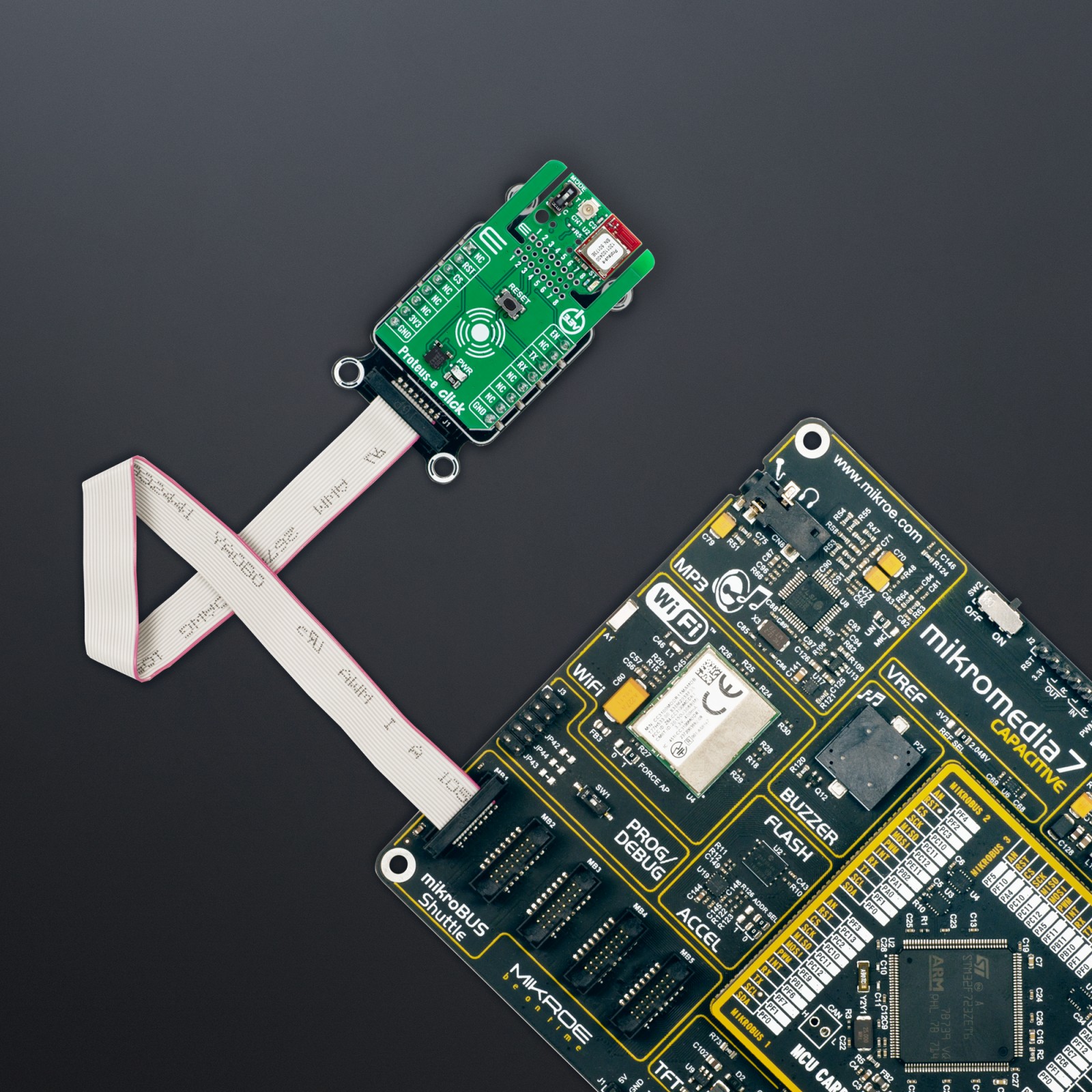
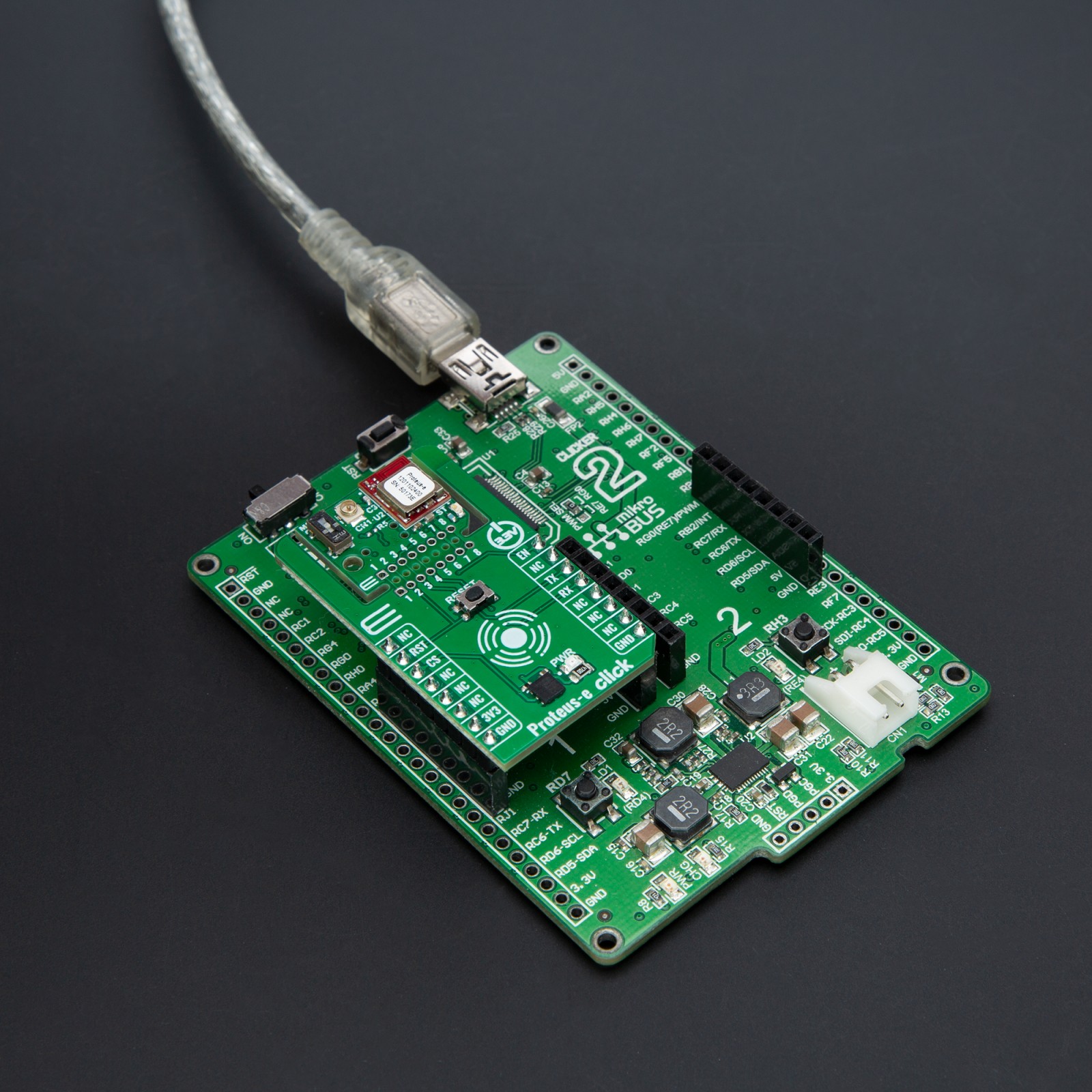
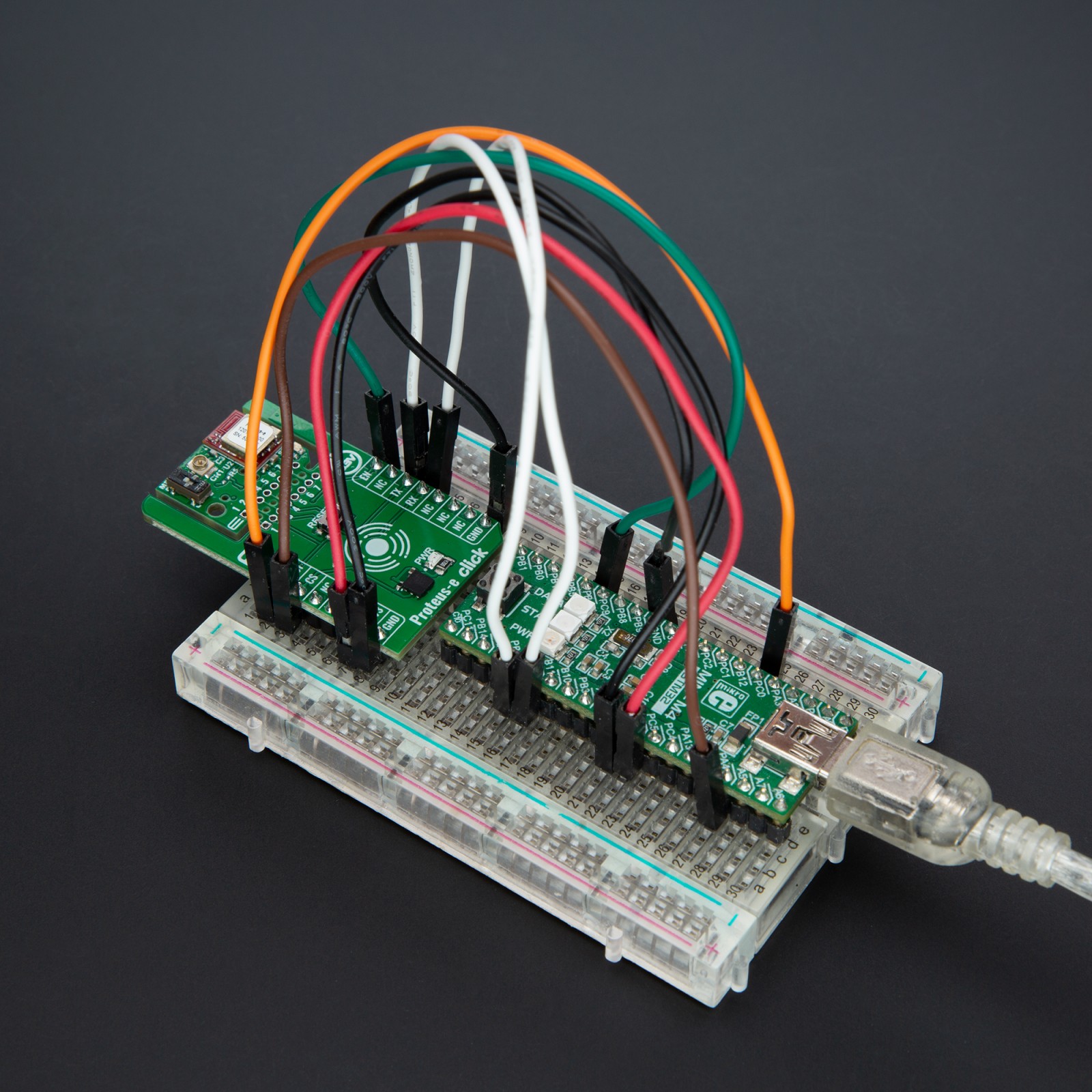
How does it work?
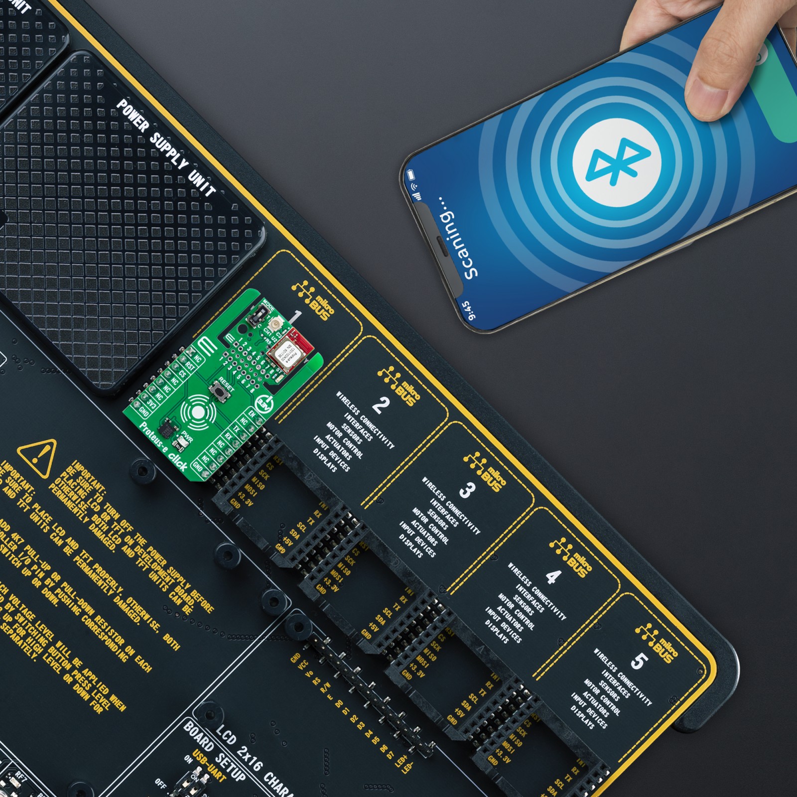
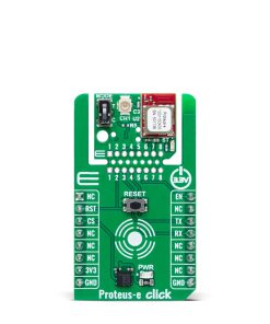
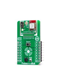
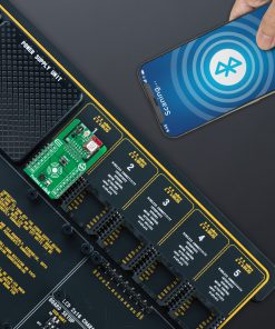
Proteus-e Click is based on the 2612011024000, a radio module for wireless communication from Würth Elektronik, designed to enable connectivity between devices such as control systems, remote controls, sensors, and similar applications. Built on Bluetooth® LE 5.1 technology, this module ensures fast, reliable, and secure data transmission in a point-to-point topology, where Proteus-e acts as a Bluetooth® LE “peripheral” device. To establish communication, the counterpart, such as a Proteus-III module or a smartphone, must implement the Bluetooth® LE “central” role, along with the relevant Bluetooth® LE profiles and characteristics that Proteus-e provides. The versatility of Proteus-e Click makes it ideal for a range of applications, including industrial automation systems, remote monitoring of sensors, smart home devices, and wireless control systems that demand low-power operation, secure data transmission, and reliable connectivity.
At the core of the 2612011024000 module lies a high-performance Bluetooth® LE chip from the nRF52 series, offering an excellent power efficiency and performance combination. The chip features a 64MHz ARM Cortex-M4 CPU, equipped with 192kB of flash memory and 24kB RAM, and delivers up to 4dBm of output power. This enables Proteus-e to achieve robust wireless communication while maintaining ultra-low power consumption, making it suitable for battery-powered applications. The module’s firmware supports an SPP-like Bluetooth® LE profile, enabling bidirectional data transmission between Proteus-e and other Bluetooth® LE devices that implement the same profile. This data transmission is secured through encrypted and authenticated connections, ensuring data integrity and protection against unauthorized access.
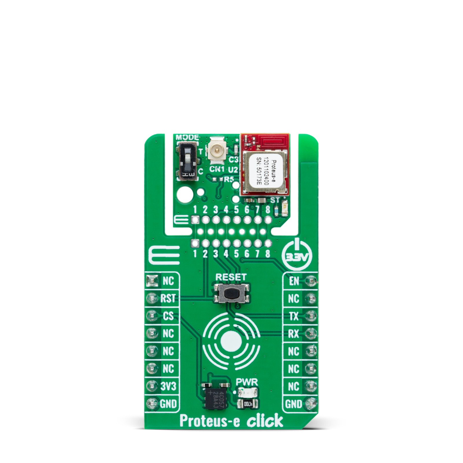
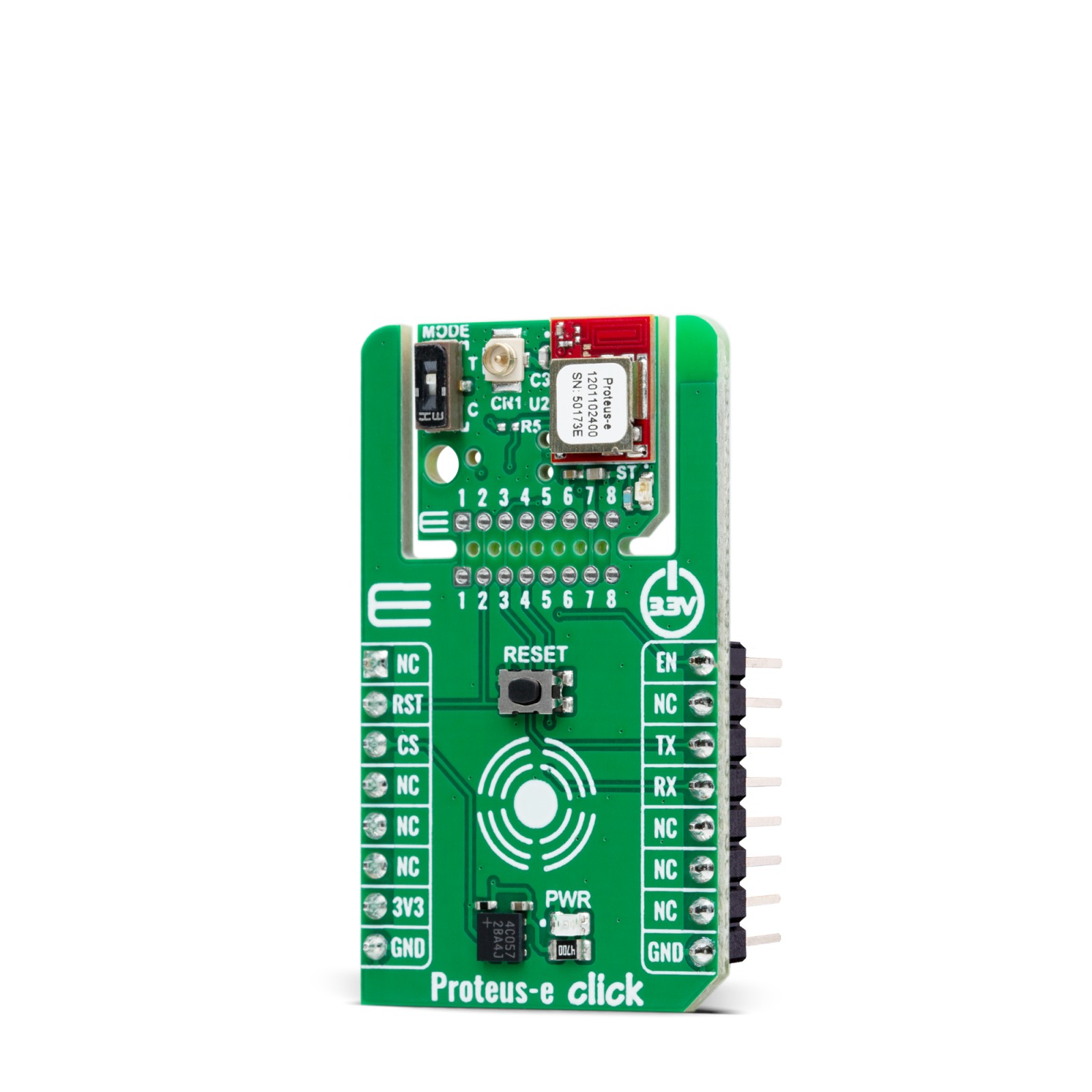
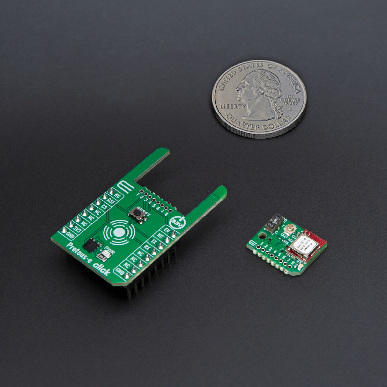
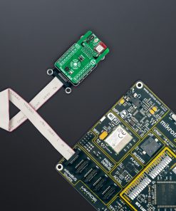
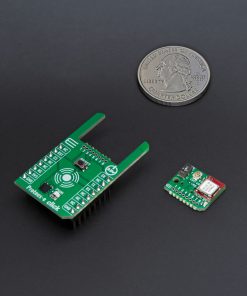
This Click board™ is designed in a unique format supporting the newly introduced MIKROE feature called “Click Snap.” Unlike the standardized version of Click boards, this feature allows the main module area to become movable by breaking the PCB, opening up many new possibilities for implementation. Thanks to the Snap feature, the 2612011024000 can operate autonomously by accessing its signals directly on the pins marked 1-8. Additionally, the Snap part includes a specified and fixed screw hole position, enabling users to secure the Snap board in their desired location.
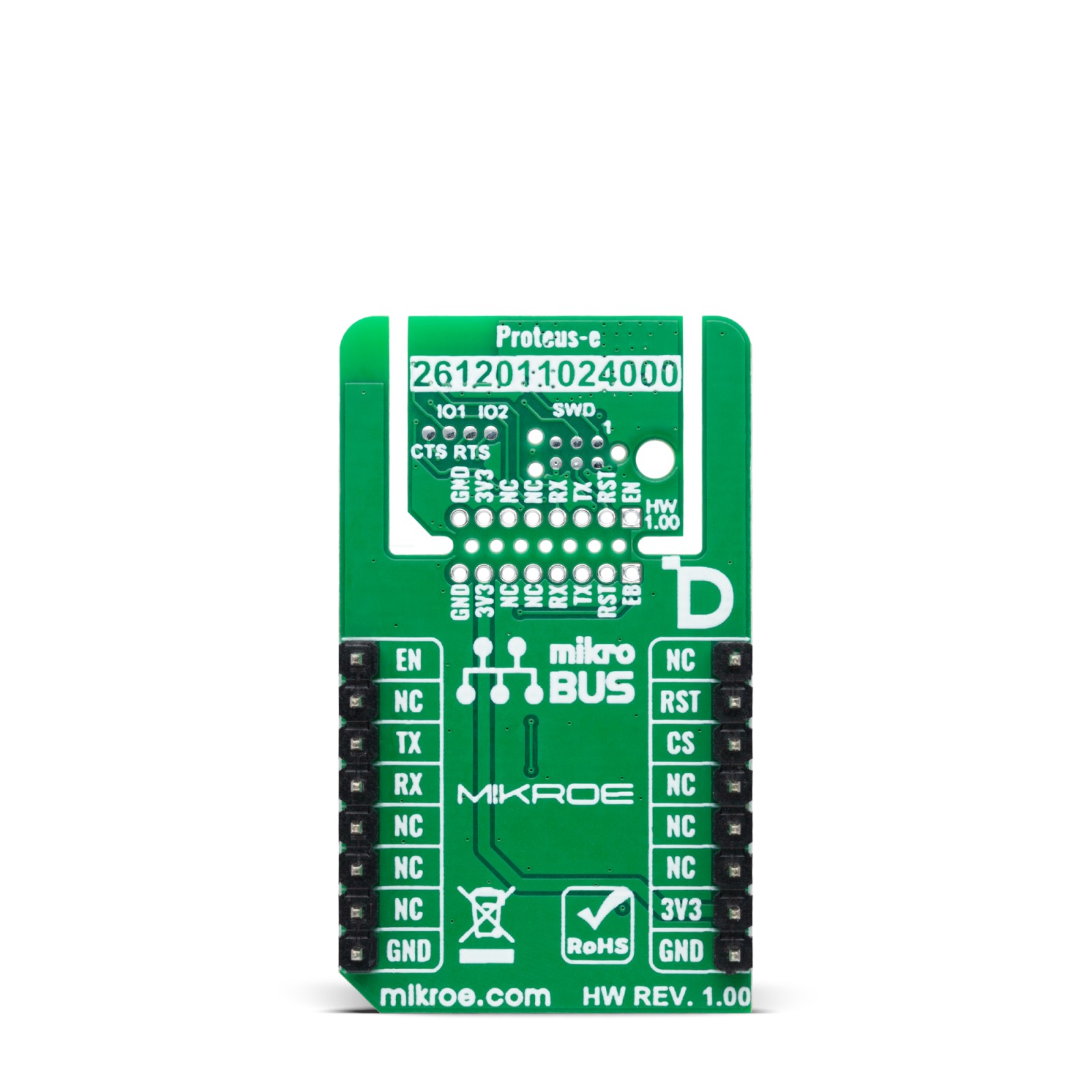
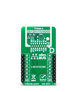
Communication between the 2612011024000 module and the host MCU is established through a UART interface, using standard UART RX and TX pins, along with hardware flow control pins (CTS/RTS – Clear to Send/Ready to Send) available as test points on the back of the board to ensure efficient and reliable data transfer. The default communication speed is set to 115200bps. In addition to the interface pins, the board features a reset (RST) pin and a RESET button for hard resetting the module when necessary. A blue status LED (ST) clearly indicates the module’s operational status, ensuring easy monitoring during use.
Furthermore, the EN pin of the mikroBUS™ socket serves multiple functions. In Transparent mode, selected via the onboard MODE switch, which toggles between Command and Transparent modes, the EN pin functions as an output pin, indicating whether the module is busy with data transmission. In Command mode, the EN pin serves as an input pin with an internal pull-up resistor, used to wake up the UART in cases where it has been previously disabled using the CMD_UARTDISABLE_REQ command. The board also features two dedicated GPIO pins, IO1 and IO2, from the Proteus-e module, which are accessible as test points located on the back of the board, enabling flexible remote control and monitoring of external devices.
The Proteus-e module is equipped with an onboard antenna for standard operation. However, this board also includes an external antenna connector (CN1), allowing the integration of an additional antenna like WiFi 2.4GHz/5.4GHz Active FPC Antenna to extend radio range when required. In addition to the antenna connector, the board includes SWD pads designed for use with MIKROE’s 6-pin Needle Cable, providing an optional flash and debug SWD (Serial Wire Debug) interface functionality.
This Click board™ can be operated only with a 3.3V logic voltage level. The board must perform appropriate logic voltage level conversion before using MCUs with different logic levels. It also comes equipped with a library containing functions and example code that can be used as a reference for further development.
Click Snap
Click Snap is an innovative feature of our standardized Click add-on boards, introducing a new level of flexibility and ease of use. This feature allows for easy detachment of the main sensor area by simply snapping the PCB along designated lines, enabling various implementation possibilities. For detailed information about Click Snap, please visit the official page dedicated to this feature.
Specifications
Type
BT/BLE
Applications
Ideal for industrial automation systems, remote monitoring of sensors, smart home devices, and wireless control systems
On-board modules
Proteus-e (2612011024000) – radio module for wireless communication from Würth Elektronik
Key Features
Bluetooth® LE 5.1 for fast, secure, and reliable point-to-point communication, module based on 64MHz ARM Cortex-M4 CPU with 192kB flash memory and 24kB RAM, UART with hardware flow control, selectable operational mode, GPIO control, antenna options, module status indicator, SWD interface, Click Snap, and more
Interface
UART
Feature
Click Snap,ClickID
Compatibility
mikroBUS™
Click board size
M (42.9 x 25.4 mm)
Input Voltage
3.3V
Pinout diagram
This table shows how the pinout on Proteus-e Click corresponds to the pinout on the mikroBUS™ socket (the latter shown in the two middle columns).
Onboard settings and indicators
Label | Name | Default | Description |
---|---|---|---|
LD1 | PWR | – | Power LED Indicator |
LD2 | ST | – | Module Status LED Indicator |
SW1 | MODE | Upper | Mode Selection T/C: Left position T, Right position C |
Proteus-e Click electrical specifications
Description | Min | Typ | Max | Unit |
---|---|---|---|---|
Supply Voltage | – | 3.3 | – | V |
Frequency Range | – | 2.4 | – | GHz |
Output Power | – | – | 4 | dBm |
Sensitivity | – | -93 | – | dBm |
Software Support
We provide a library for the Proteus-e Click as well as a demo application (example), developed using MIKROE compilers. The demo can run on all the main MIKROE development boards.
Package can be downloaded/installed directly from NECTO Studio Package Manager (recommended), downloaded from our LibStock™ or found on MIKROE github account.
Library Description
This library contains API for Proteus-e Click driver.
Key functions
-
proteuse_send_cmd
This function sends a desired command packet from the click context object. -
proteuse_read_event
This function reads an event packet from the ring buffer and stores it in the click context object. -
proteuse_get_user_setting
This function reads data from the desired user settings index and stores it in the click context event packet object.
Example Description
This example demonstrates the use of Proteus-e Click by processing data from a connected BT device.
void application_task ( void )
{
if ( PROTEUSE_OK == proteuse_read_event ( &proteuse ) )
{
proteuse_parse_event ( &proteuse );
}
}
The full application code, and ready to use projects can be installed directly from NECTO Studio Package Manager (recommended), downloaded from our LibStock™ or found on MIKROE github account.
Other MIKROE Libraries used in the example:
- MikroSDK.Board
- MikroSDK.Log
- Click.Proteuse
Additional notes and informations
Depending on the development board you are using, you may need USB UART click, USB UART 2 Click or RS232 Click to connect to your PC, for development systems with no UART to USB interface available on the board. UART terminal is available in all MIKROE compilers.
mikroSDK
This Click board™ is supported with mikroSDK – MIKROE Software Development Kit. To ensure proper operation of mikroSDK compliant Click board™ demo applications, mikroSDK should be downloaded from the LibStock and installed for the compiler you are using.
For more information about mikroSDK, visit the official page.