How does it work?
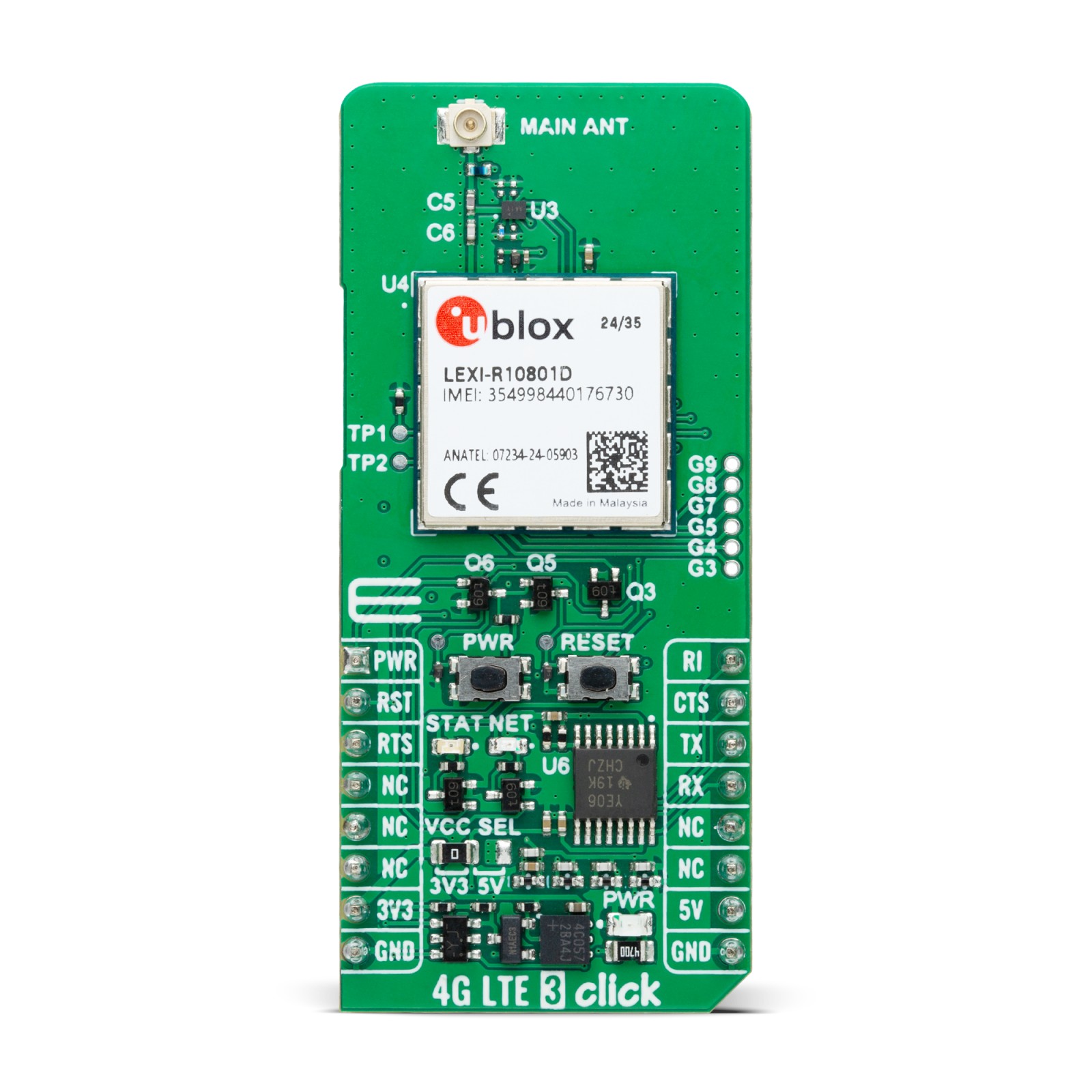
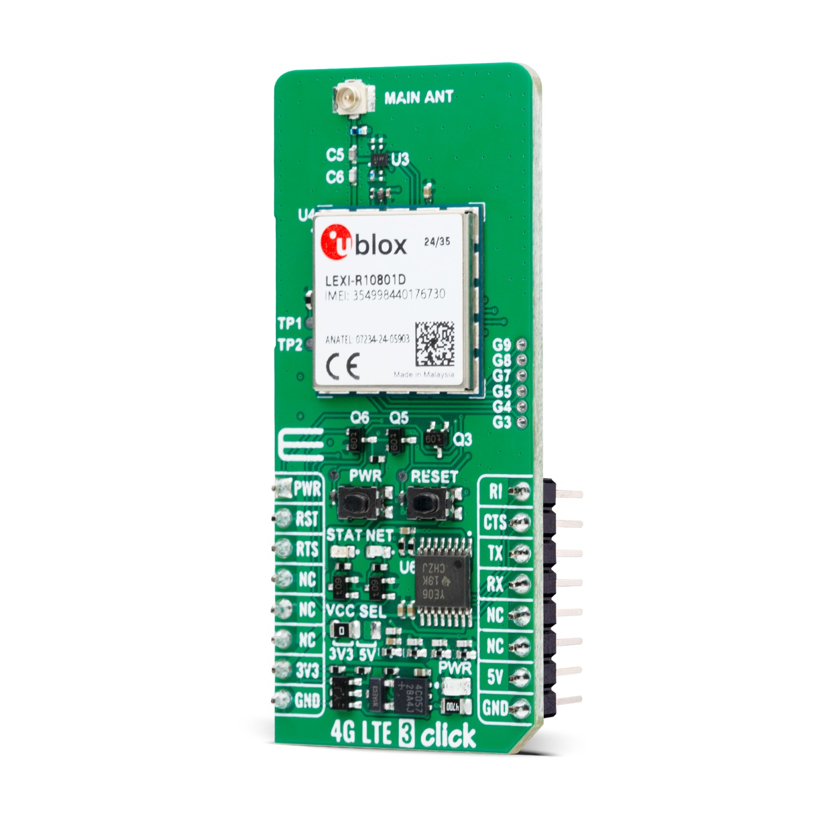
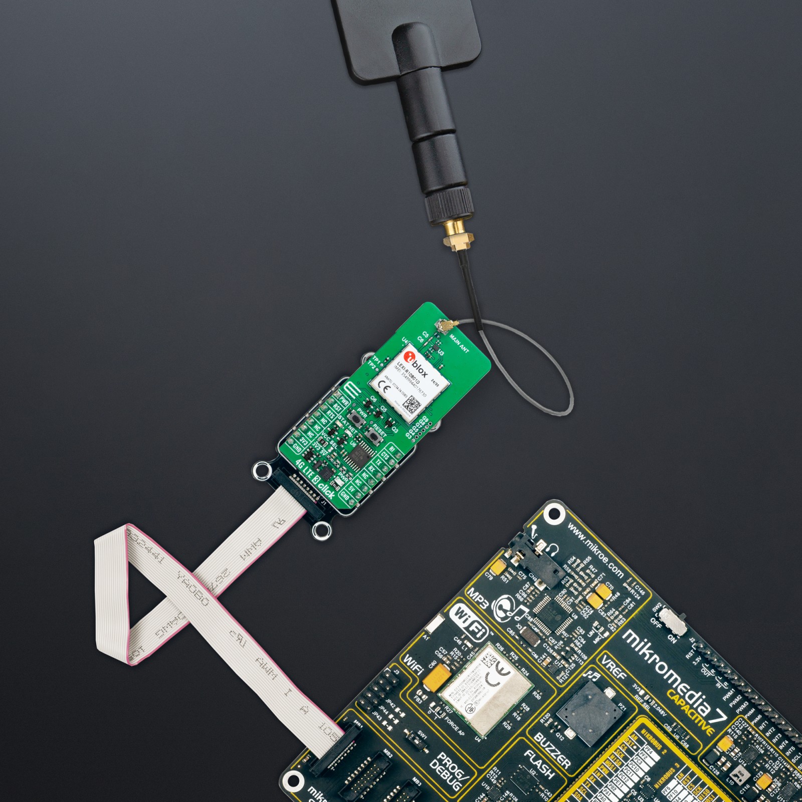
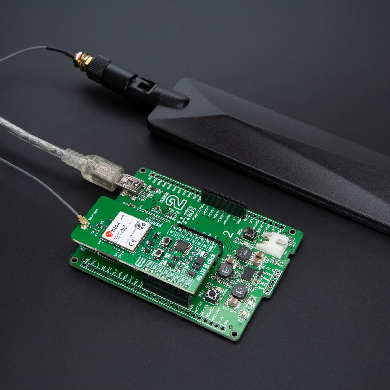
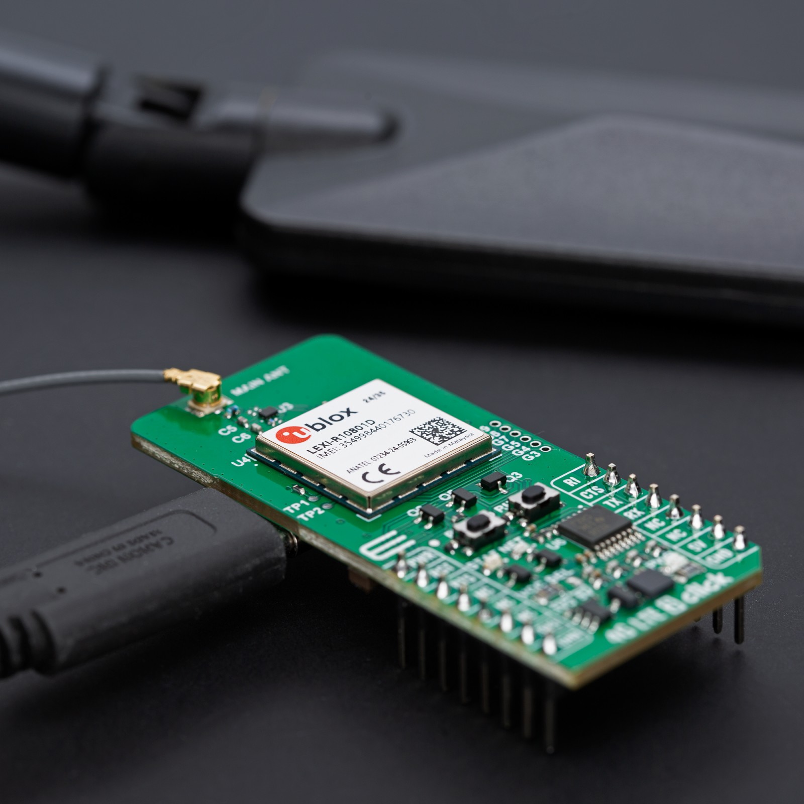
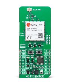
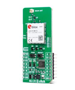
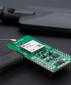
4G LTE 3 Click (for Europe) is based on the LEXI-R10801D, a single-mode LTE Cat 1bis module from u-blox, made for applications requiring reliable connectivity, medium data speeds, and extensive coverage in the EMEA, APAC, and Brazilian regions. The LEXI-R10801D module is designed to meet professional-grade standards, adhering to the u-blox qualification policy and the stringent AEC-Q104 standard. It supports various LTE FDD bands, including 1, 3, 5, 7, 8, 20, and 28, ensuring broad compatibility and superior performance across multiple regional networks. Additionally, the module has regulatory certifications such as RED, NCC, RCM, and Anatel, allowing seamless deployment across supported markets. Beyond its LTE functionality, the LEXI-R10801D integrates an embedded Wi-Fi scan, enabling the scanning of Wi-Fi hotspots for enhanced indoor positioning, and supports the u-blox CellLocate® service for advanced geolocation capabilities.
This compact and highly integrated module offers medium-capacity data connectivity, achieving download speeds of up to 10Mbps and upload speeds of 5Mbps, all while maintaining exceptionally low power consumption. These features make it an ideal choice for cost-sensitive applications that demand moderate data speeds and reliable coverage. Its versatile use cases include asset tracking, telematics, healthcare devices, and wearables, where efficient and robust connectivity is paramount.
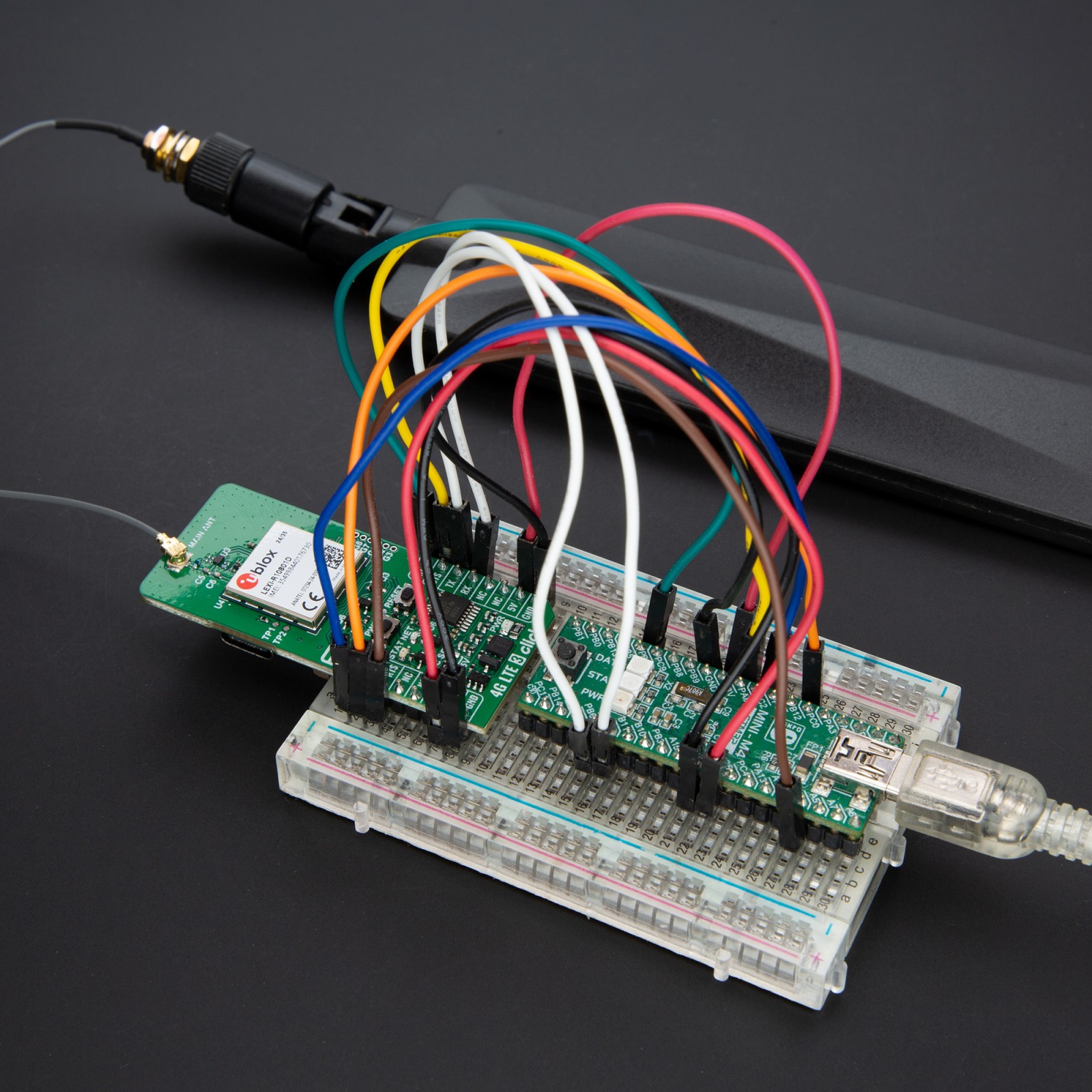
Communication between the LEXI-R10801D and the host MCU is made through a UART interface, using standard UART RX and TX pins and hardware flow control pins (CTS/RTS/RI – Clear to Send/Ready to Send/Ring Indicator) for efficient data transfer. The module defaults to a communication speed of 115200bps, allowing for seamless data exchange over AT commands.
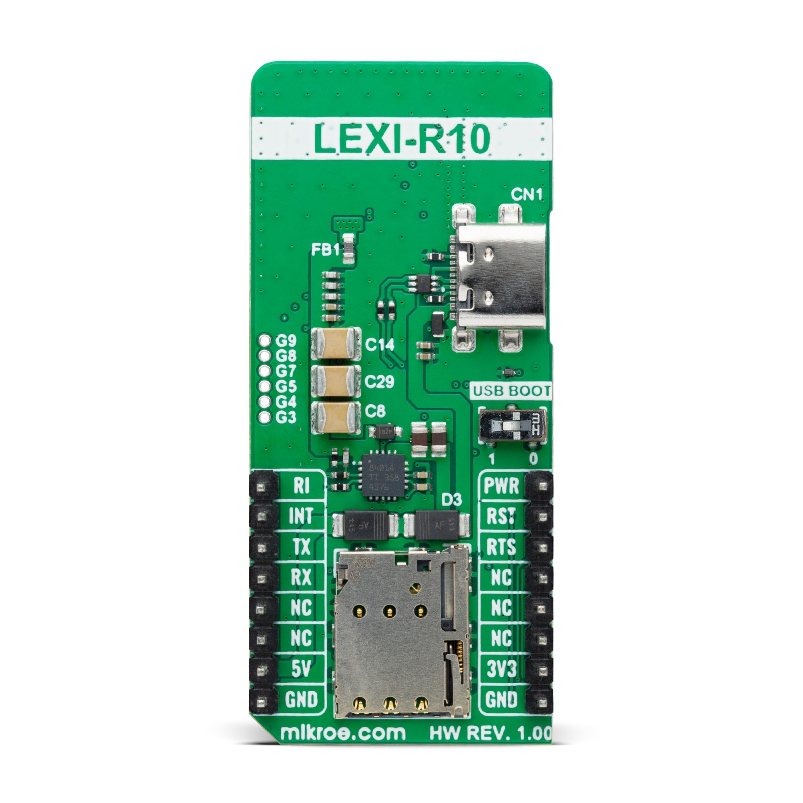
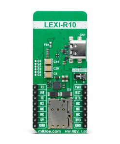
This Click board™ also includes a USB Type C connector for power and data transfer, which is compliant with the USB 2.0 specification with a maximum 480Mbit/s data rate (peripheral only). In addition to this interface, the board also features a USB FW upgrade switch on the back of the board labeled USB BOOT to manage firmware upgrades. This switch has positions 0 for normal operation and 1 for firmware upgrades over USB, ensuring a straightforward upgrade process.
The 4G LTE 3 Click includes several additional functionalities that enhance its usability and control. The PWR button allows users to easily power the module ON or OFF, while the RESET button provides a quick way to reset the module. These functions can also be controlled digitally via the mikroBUS™ pins PWR and RST, offering greater flexibility. The board also includes an unsoldered header with six GPIO pins, allowing for further customization. Moreover, this board also has dedicated test points for diagnostic purposes, TP1 and TP2, if the host MCU uses the USB and main UART interfaces and two visual indicators to provide real-time status updates.
The first red NET LED indicates the current network status of the module. The device has successfully registered on the network when the LED blinks slowly. If the LED blinks at a normal pace, the device has not yet registered to a network. A fast blinking pattern signals data transmission. When the LED is completely OFF, it indicates that the device is either powered OFF or in Power Saving Mode (PSM). The second yellow STAT LED indicates the module’s power status, which stays off when the module is OFF and turns ON when the module is powered on or firmware ready.
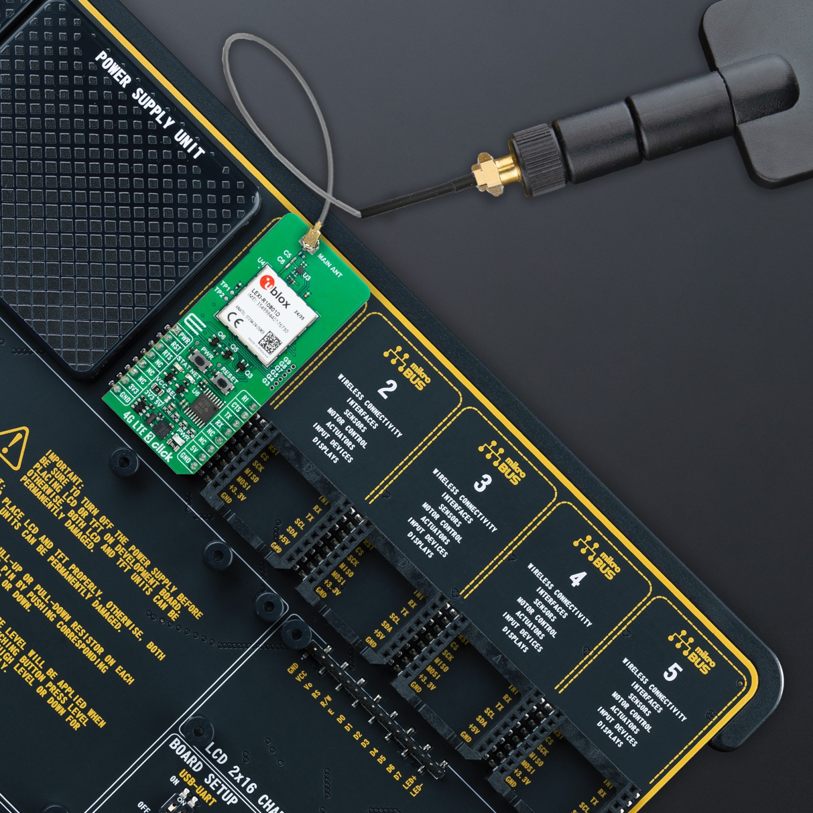
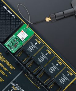
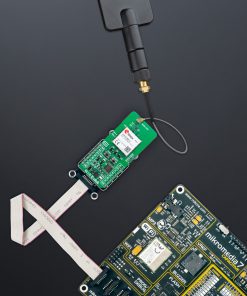
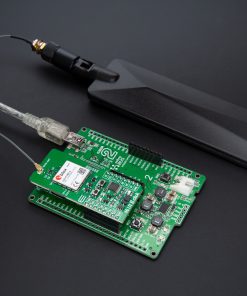
The board features one u.Fl connector for the main LTE antenna that MIKROE offers, like the LTE Flat Rotation Antenna combined with an IPEX-SMA cable for flexible and efficient connectivity. The board also has a micro SIM card holder that supports both 1.8V and 3.0V uSIM cards, allowing users to select the most appropriate service provider for their particular use case.
This Click board™ can operate with both 3.3V and 5V logic voltage levels selected via the VCC SEL jumper. Since the LEXI-R10801D module operates at 3.8V, a logic-level translator, the TXB0106 is also used for proper operation and an accurate signal-level translation. This way, both 3.3V and 5V capable MCUs can use the communication lines properly. Also, this Click board™ comes equipped with a library containing easy-to-use functions and an example code that can be used as a reference for further development.
Specifications
Type
GSM/LTE
Applications
Ideal for applications like asset tracking, telematics, healthcare devices, and wearables
On-board modules
LEXI-R10801D – single-mode LTE Cat 1bis module from u-blox
Radio Region
Professional grade LTE Cat 1bis module, various LTE FDD bands, embedded Wi-Fi scan, geolocation service, UART and USB interfaces, firmware upgrade, additional control options, uSIM card support, regulatory certifications (RED, NCC, RCM, Anatel), and more
Interface
UART
Feature
ClickID
Compatibility
mikroBUS™
Click board size
L (57.15 x 25.4 mm)
Input Voltage
3.3V or 5V,External
Pinout diagram
This table shows how the pinout on 4G LTE 3 Click (for Europe) corresponds to the pinout on the mikroBUS™ socket (the latter shown in the two middle columns).
Onboard settings and indicators
Label | Name | Default | Description |
---|---|---|---|
LD1 | PWR | – | Power LED Indicator |
LD2 | NET | – | Network Activity Status LED Indicator |
LD3 | STAT | – | Module Operational Status LED Indicator |
JP1 | VCC SEL | Left | Power Voltage Level Selection 3V3/5V: Left position 3V3, Right position 5V |
T1 | PWR | – | Module Power-ON Button |
T2 | RESET | – | Module Reset Button |
SW1 | USB BOOT | Right | USB FW Upgrade Switch 0/1: Left position 0, Right position 1 |
4G LTE 3 Click (for Europe) electrical specifications
Description | Min | Typ | Max | Unit |
---|---|---|---|---|
Supply Voltage | 3.3 | – | 5 | V |
LTE Frequency Range | 700 | – | 2600 | MHz |
LTE Output Power | – | – | +24 | dBm |
LTE RX Sensitivity | -94 | – | -108 | dBm |
Software Support
We provide a library for the 4G LTE 3 E Click as well as a demo application (example), developed using MIKROE compilers. The demo can run on all the main MIKROE development boards.
Package can be downloaded/installed directly from NECTO Studio Package Manager (recommended), downloaded from our LibStock™ or found on MIKROE github account.
Library Description
This library contains API for 4G LTE 3 E Click driver.
Key functions
-
c4glte3e_set_sim_apn
This function sets APN for sim card. -
c4glte3e_send_sms_text
This function sends text message to a phone number. -
c4glte3e_cmd_run
This function sends a specified command to the click module.
Example Description
Application example shows device capability of connecting to the network and sending SMS or TCP/UDP messages using standard “AT” commands.
void application_task ( void )
{
switch ( app_state )
{
case C4GLTE3E_POWER_UP:
{
if ( C4GLTE3E_OK == c4glte3e_power_up( &c4glte3e ) )
{
app_state = C4GLTE3E_CONFIG_CONNECTION;
log_printf( &logger, ">>> APP STATE - CONFIG CONNECTION <<<rnn" );
}
break;
}
case C4GLTE3E_CONFIG_CONNECTION:
{
if ( C4GLTE3E_OK == c4glte3e_config_connection( &c4glte3e ) )
{
app_state = C4GLTE3E_CHECK_CONNECTION;
log_printf( &logger, ">>> APP STATE - CHECK CONNECTION <<<rnn" );
}
break;
}
case C4GLTE3E_CHECK_CONNECTION:
{
if ( C4GLTE3E_OK == c4glte3e_check_connection( &c4glte3e ) )
{
app_state = C4GLTE3E_CONFIG_EXAMPLE;
log_printf( &logger, ">>> APP STATE - CONFIG EXAMPLE <<<rnn" );
}
break;
}
case C4GLTE3E_CONFIG_EXAMPLE:
{
if ( C4GLTE3E_OK == c4glte3e_config_example( &c4glte3e ) )
{
app_state = C4GLTE3E_EXAMPLE;
log_printf( &logger, ">>> APP STATE - EXAMPLE <<<rnn" );
}
break;
}
case C4GLTE3E_EXAMPLE:
{
c4glte3e_example( &c4glte3e );
break;
}
default:
{
log_error( &logger, " APP STATE." );
break;
}
}
}
The full application code, and ready to use projects can be installed directly from NECTO Studio Package Manager (recommended), downloaded from our LibStock™ or found on MIKROE github account.
Other MIKROE Libraries used in the example:
- MikroSDK.Board
- MikroSDK.Log
- Click.4GLTE3E
Additional notes and informations
Depending on the development board you are using, you may need USB UART click, USB UART 2 Click or RS232 Click to connect to your PC, for development systems with no UART to USB interface available on the board. UART terminal is available in all MIKROE compilers.
mikroSDK
This Click board™ is supported with mikroSDK – MIKROE Software Development Kit. To ensure proper operation of mikroSDK compliant Click board™ demo applications, mikroSDK should be downloaded from the LibStock and installed for the compiler you are using.
For more information about mikroSDK, visit the official page.