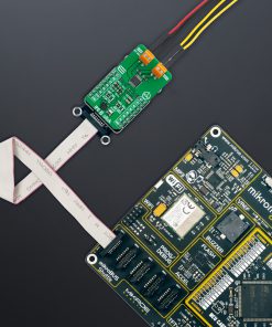
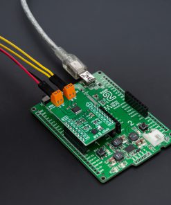
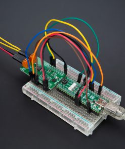
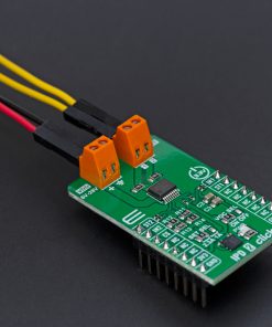
How does it work?
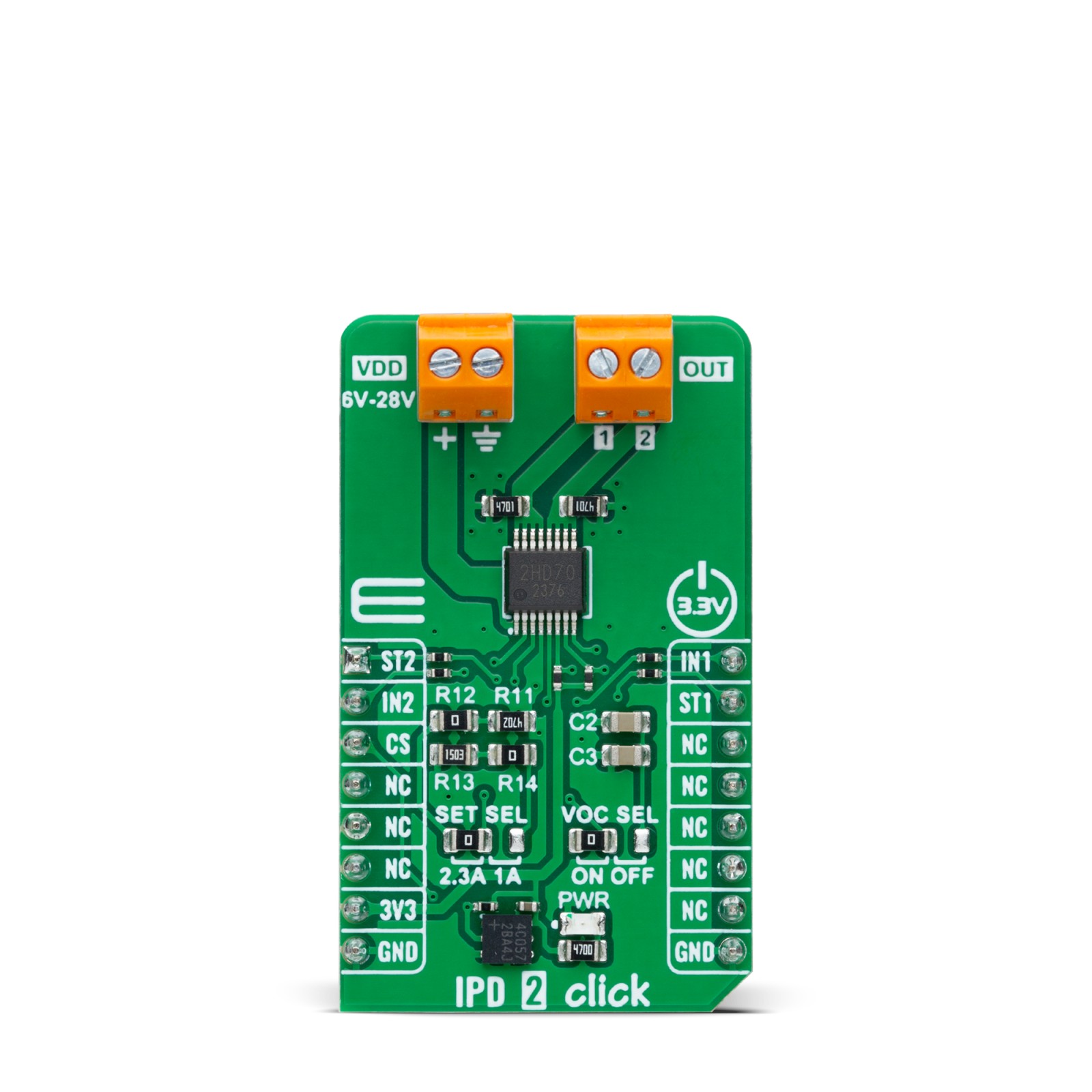
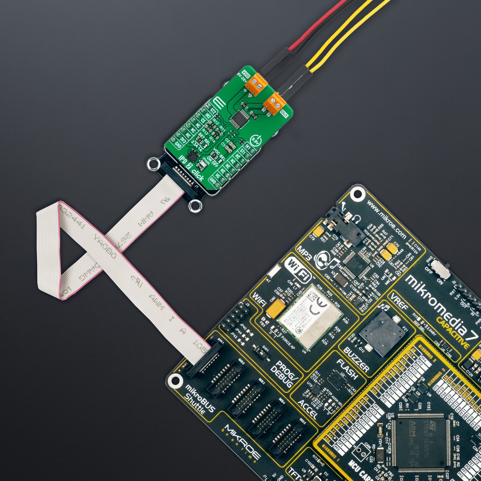
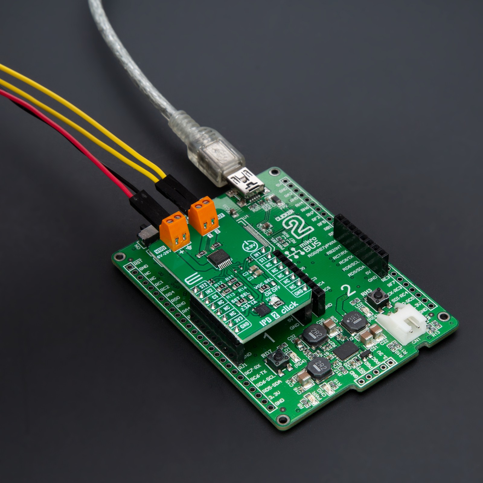
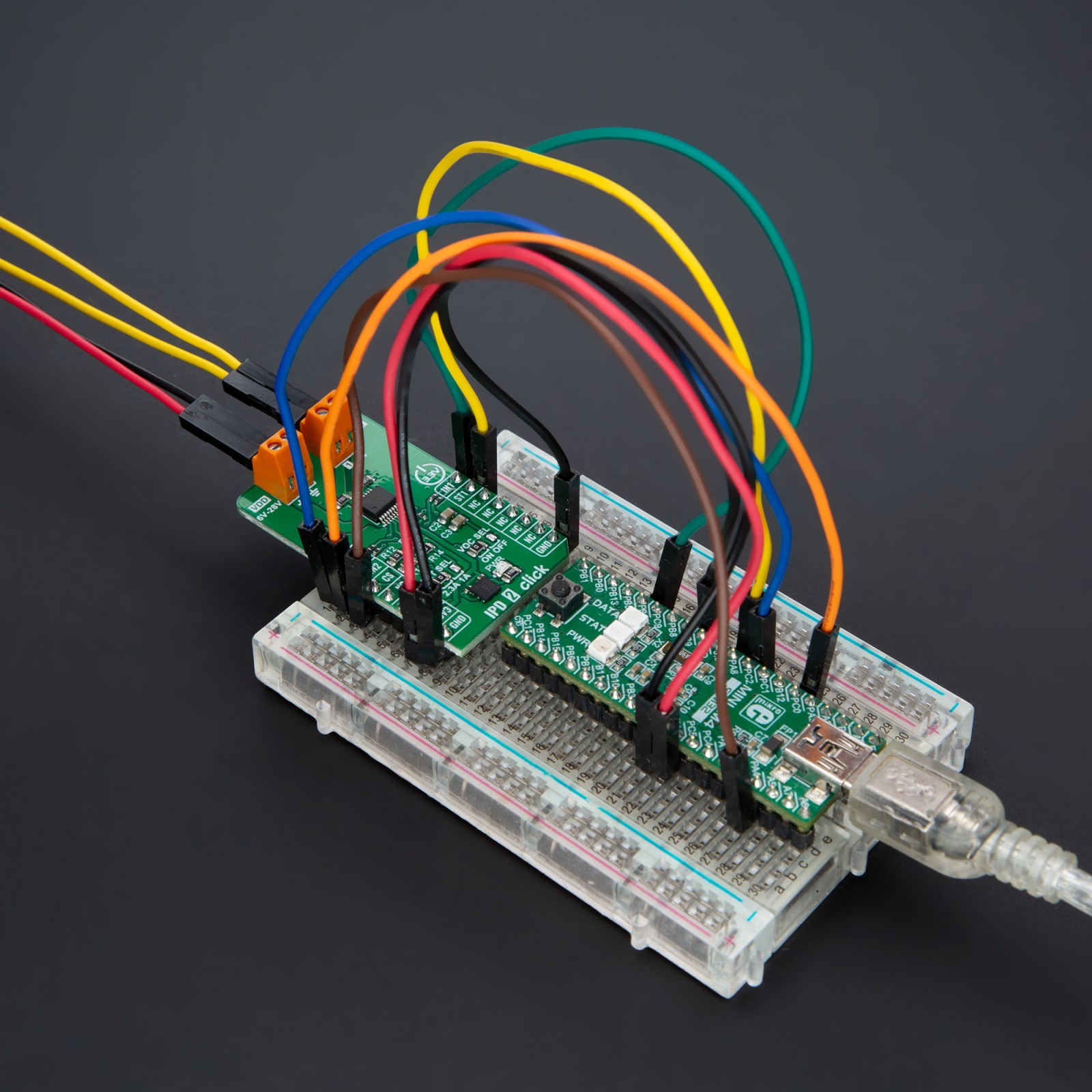
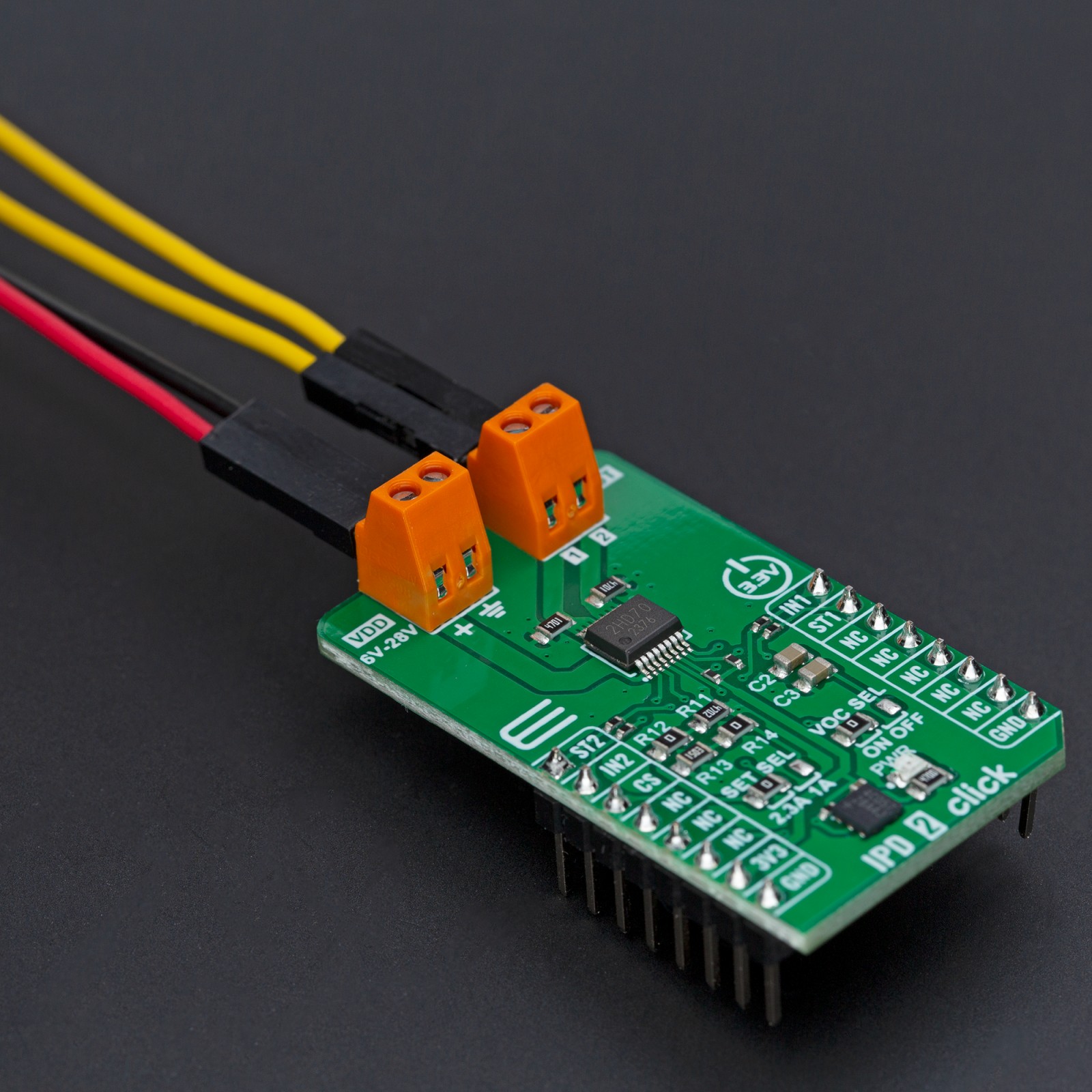
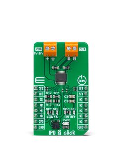
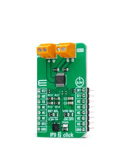
IPD 2 Click is based on the BV2HD070EFU-C, an automotive-grade two-channel high-side switch from ROHM Semiconductor, designed to handle resistive, inductive, and capacitive loads in automotive applications. The BV2HD070EFU-C features a 70mΩ on-resistance high-side switch and incorporates advanced protection and diagnostic functionalities to ensure reliable operation in demanding environments. This Click board™ is particularly suitable for automotive applications, supporting various types of loads such as lights, solenoids, and motors. It provides an efficient, reliable, and compact solution for high-side switching requirements, ensuring stable performance and enhanced safety in automotive systems.
The BV2HD070EFU-C is AEC-Q100 qualified (Grade 1) and operates across a wide input voltage range of 6V to 28V, supplied via the VDD terminal. Its comprehensive protection suite includes overcurrent detection (OCD) with a configurable mask function, ensuring precise fault management and preventing unintended load disconnection. Additional safety features include thermal shutdown protection, which halts operation under excessive temperature conditions, and undervoltage lockout (UVLO) to safeguard against unstable power supply conditions. Moreover, the switch includes an open load detection function, providing feedback when the load is disconnected or the circuit is incomplete.
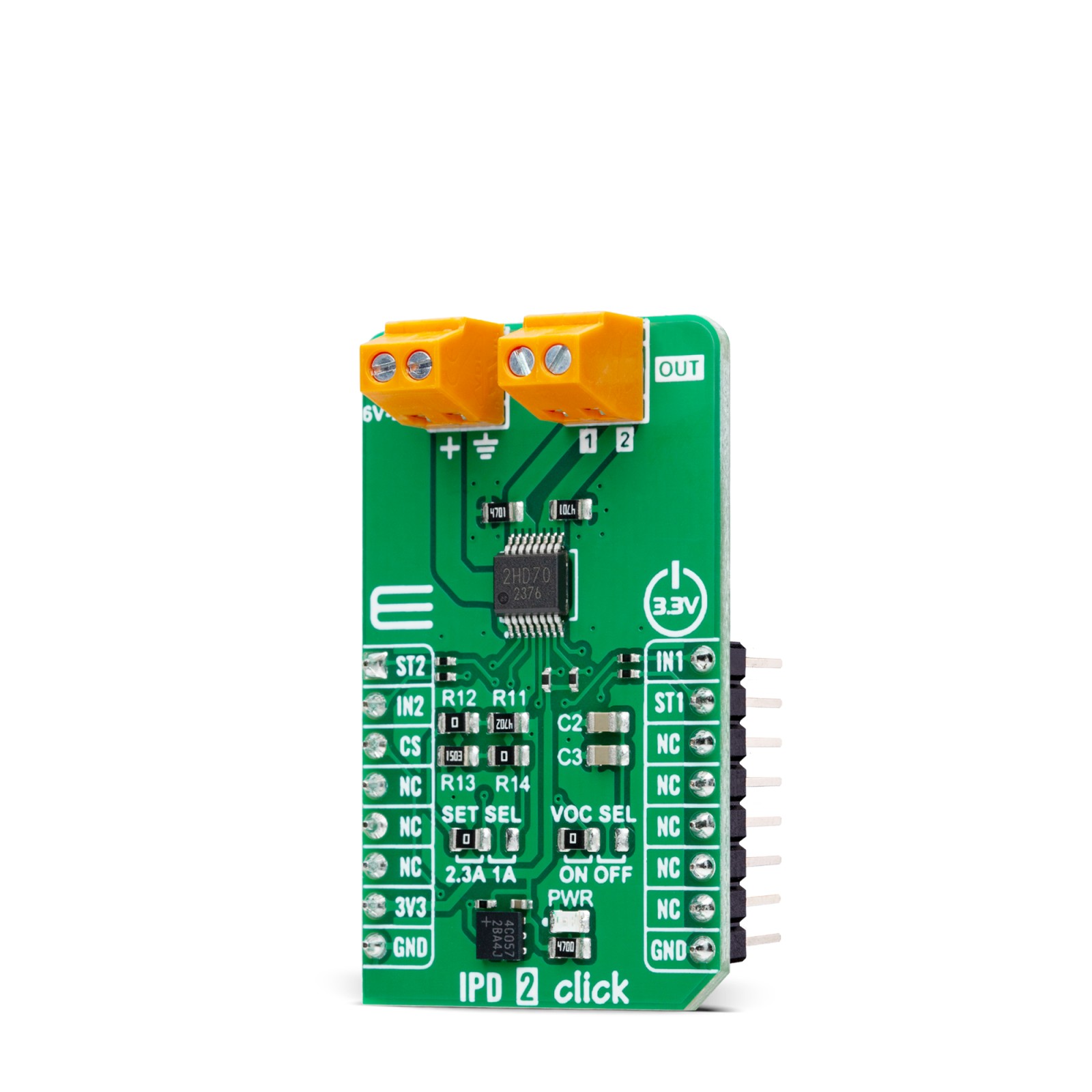
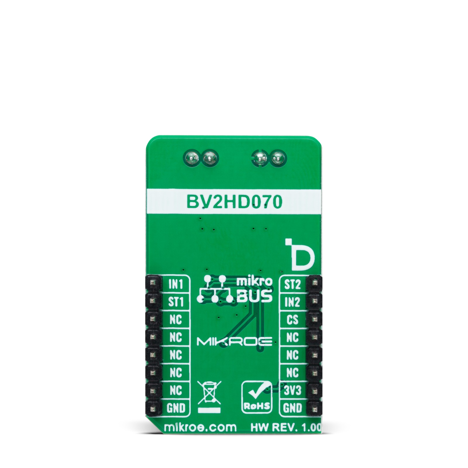
This Click board™ uses several pins of the mikroBUS™ socket for control and diagnostics. The IN1 and IN2 pins serve as control signals, enabling activation of the respective outputs marked as 1 and 2 on the output OUT terminal. For monitoring and fault detection, the board includes a diagnostic output function accessible via the ST1 and ST2 pins of the mikroBUS™ socket, providing real-time feedback on abnormalities.
In addition to these control and diagnostic pins, the board features two configuration jumpers. The first, SET SEL, allows users to configure the overcurrent limit between 1A and the default value of 2.3A. While the BV2HD070EFU-C supports overcurrent limits of up to approximately 10A, users can achieve this by replacing the selected resistance as specified in the datasheet recommendations. The second jumper, VOC SEL, activates a functionality that optimizes the time required to achieve precise overcurrent protection for the connected load. This feature is enabled by default, ensuring enhanced load safety and performance without additional configuration.
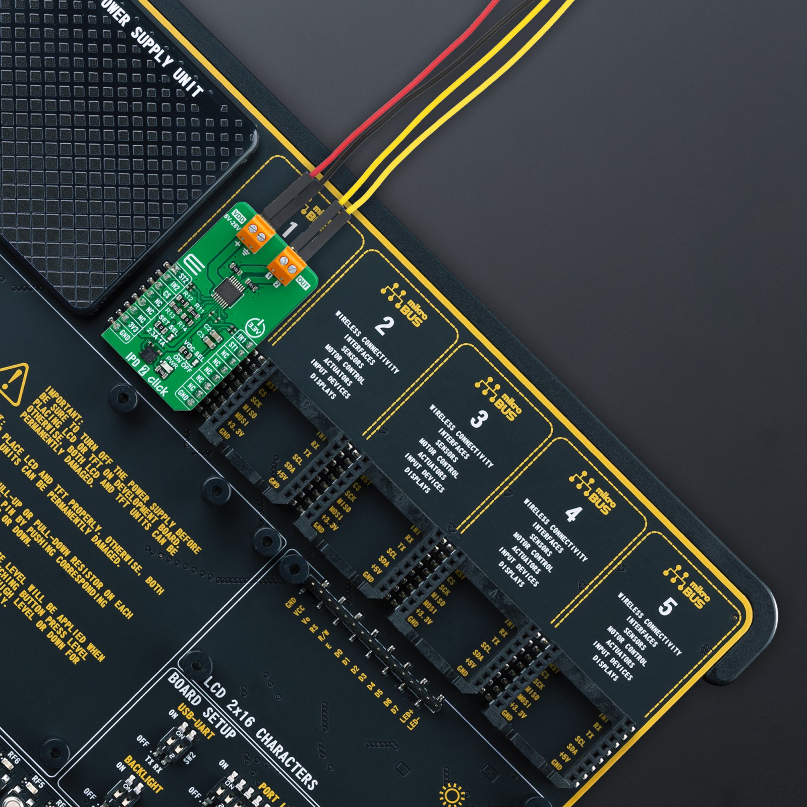
This Click board™ can be operated only with a 3.3V logic voltage level. The board must perform appropriate logic voltage level conversion before using MCUs with different logic levels. It also comes equipped with a library containing functions and example code that can be used as a reference for further development.
Specifications
Type
Power Switch
Applications
Suitable for controlling resistive, inductive, and capacitive loads such as automotive lighting, motor control, and solenoid operation
On-board modules
BV2HD070EFU-C – automotive two-channel high-side switch from ROHM Semiconductor
Key Features
AEC-Q100 qualified (Grade 1), 70mΩ on-resistance, wide operating voltage range, overcurrent detection (OCD) with configurable limits, thermal shutdown, undervoltage lockout (UVLO), open load detection, configurable overcurrent limit and timing, and more
Interface
GPIO
Feature
ClickID
Compatibility
mikroBUS™
Click board size
M (42.9 x 25.4 mm)
Input Voltage
3.3V,External
Pinout diagram
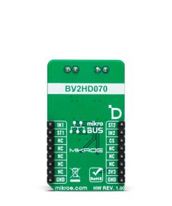
This table shows how the pinout on IPD 2 Click corresponds to the pinout on the mikroBUS™ socket (the latter shown in the two middle columns).
Onboard settings and indicators
Label | Name | Default | Description |
---|---|---|---|
LD1 | PWR | – | Power LED Indicator |
JP1 | SET SEL | Left | Overcurrent Threshold Selection 2.3A/1A: Left position 2.3A, Right position 1A |
JP2 | VOC SEL | Left | Overcurrent Mask Time Selection ON/OFF: Left position ON, Right position OFF |
IPD 2 Click electrical specifications
Description | Min | Typ | Max | Unit |
---|---|---|---|---|
Supply Voltage | – | 3.3 | – | V |
External Power Supply | 6 | – | 28 | V |
Current Limit | – | – | 2.3 | A |
Software Support
We provide a library for the IPD 2 Click as well as a demo application (example), developed using MIKROE compilers. The demo can run on all the main MIKROE development boards.
Package can be downloaded/installed directly from NECTO Studio Package Manager (recommended), downloaded from our LibStock™ or found on MIKROE github account.
Library Description
This library contains API for IPD 2 Click driver.
Key functions
-
ipd2_enable_out1
This function enables OUT1 by setting the IN1 pin to high logic state. -
ipd2_disable_out1
This function disables OUT1 by setting the IN1 pin to low logic state. -
ipd2_get_st1_pin
This function returns the ST1 pin logic state.
Example Description
This example demonstrates the use of IPD 2 Click by toggling the output state.
void application_task ( void )
{
ipd2_enable_out1 ( &ipd2 );
ipd2_disable_out2 ( &ipd2 );
Delay_ms ( 100 );
log_printf( &logger, " OUT1: enabledrn" );
log_printf( &logger, " OUT2: disabledrn" );
log_printf( &logger, " ST1: %srn", ( char * ) ( ipd2_get_st1_pin ( &ipd2 ) ? "high" : "low" ) );
log_printf( &logger, " ST2: %srnn", ( char * ) ( ipd2_get_st2_pin ( &ipd2 ) ? "high" : "low" ) );
Delay_ms ( 1000 );
Delay_ms ( 1000 );
Delay_ms ( 1000 );
ipd2_disable_out1 ( &ipd2 );
ipd2_enable_out2 ( &ipd2 );
Delay_ms ( 100 );
log_printf( &logger, " OUT1: disabledrn" );
log_printf( &logger, " OUT2: enabledrn" );
log_printf( &logger, " ST1: %srn", ( char * ) ( ipd2_get_st1_pin ( &ipd2 ) ? "high" : "low" ) );
log_printf( &logger, " ST2: %srnn", ( char * ) ( ipd2_get_st2_pin ( &ipd2 ) ? "high" : "low" ) );
Delay_ms ( 1000 );
Delay_ms ( 1000 );
Delay_ms ( 1000 );
}
The full application code, and ready to use projects can be installed directly from NECTO Studio Package Manager (recommended), downloaded from our LibStock™ or found on MIKROE github account.
Other MIKROE Libraries used in the example:
- MikroSDK.Board
- MikroSDK.Log
- Click.IPD2
Additional notes and informations
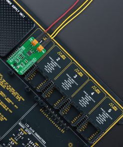
Depending on the development board you are using, you may need USB UART click, USB UART 2 Click or RS232 Click to connect to your PC, for development systems with no UART to USB interface available on the board. UART terminal is available in all MIKROE compilers.
mikroSDK
This Click board™ is supported with mikroSDK – MIKROE Software Development Kit. To ensure proper operation of mikroSDK compliant Click board™ demo applications, mikroSDK should be downloaded from the LibStock and installed for the compiler you are using.
For more information about mikroSDK, visit the official page.