DIGI I/O Click
R835.00 ex. VAT
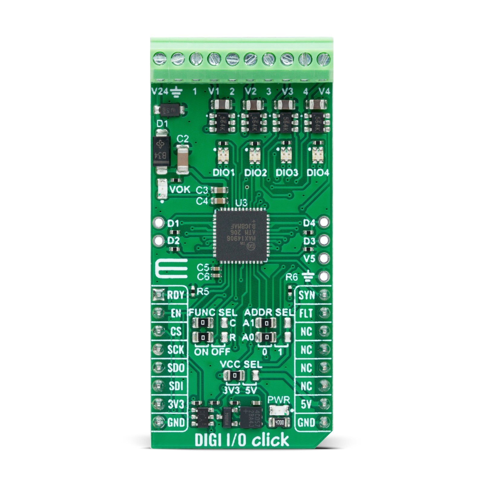
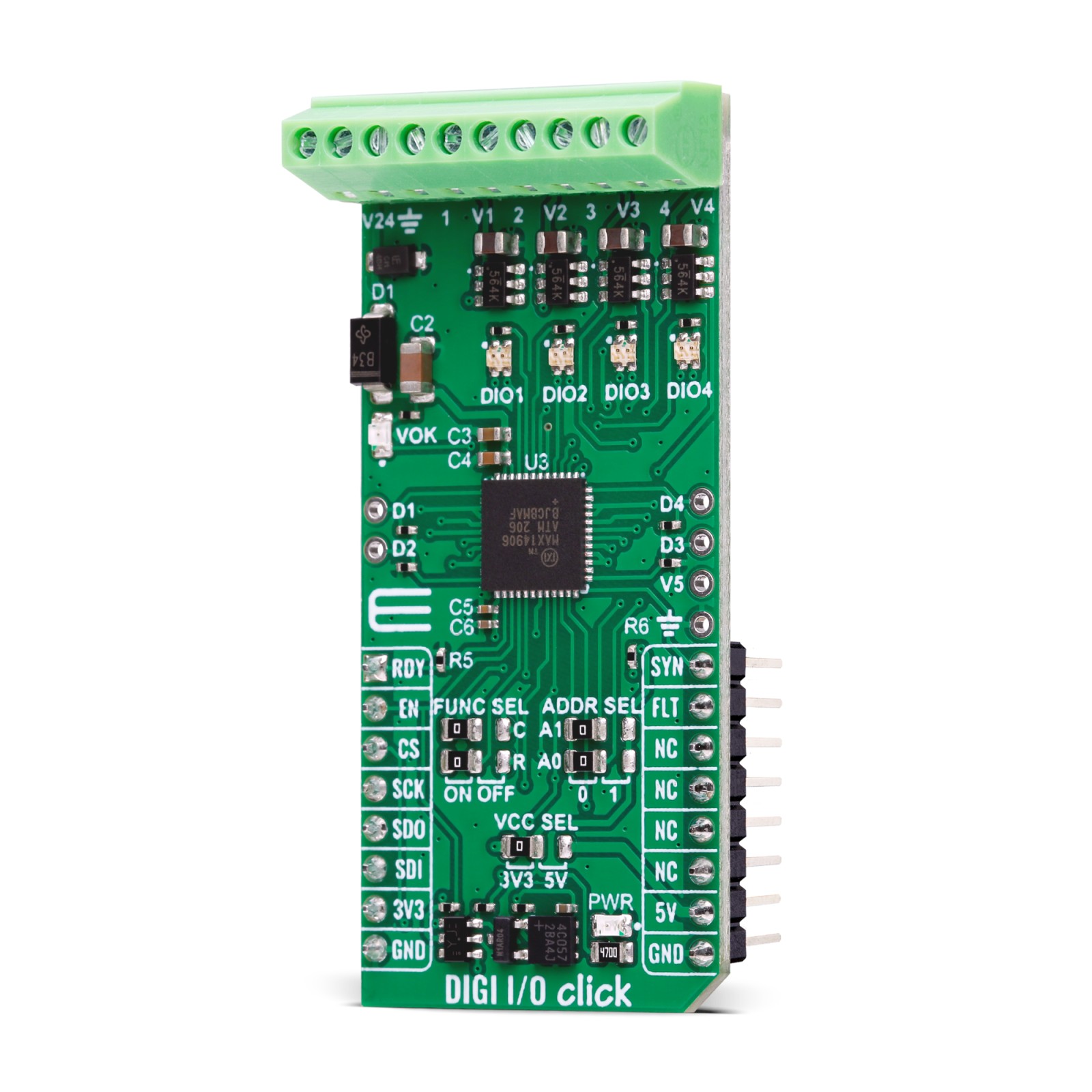
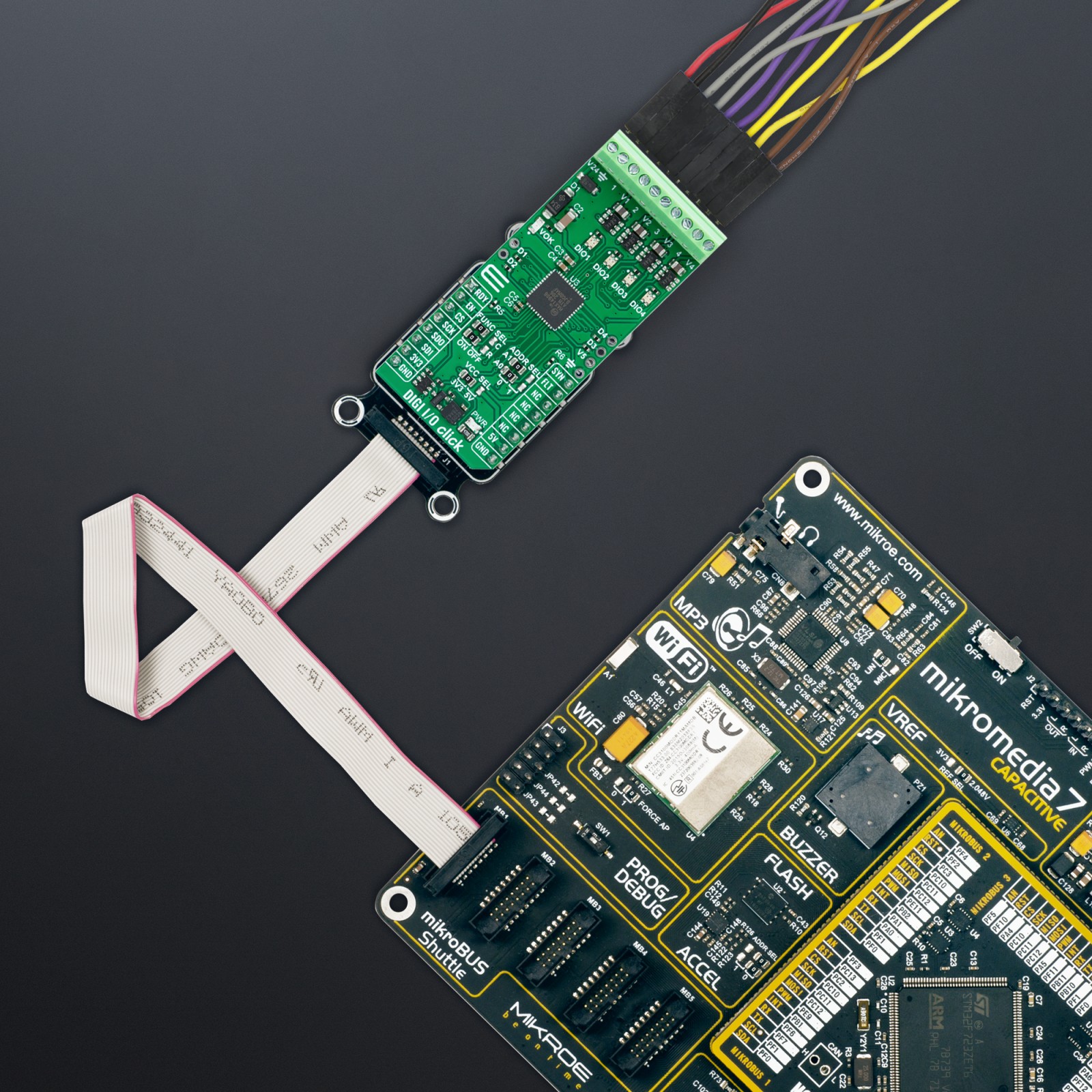
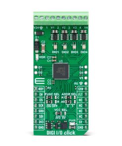
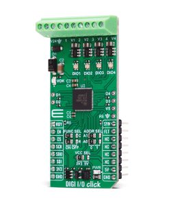
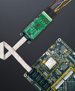
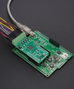
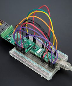
DIGI I/O Click is a compact add-on board for flexible industrial digital input and output control. This board features the MAX14906, a quad-channel industrial digital input/output IC from Analog Devices, compliant with IEC 61131-2 standard. Each channel can be individually configured as a high-side switch, push-pull driver, or digital input, supporting various operating modes with current limiting up to 1.2A and fast signal transmission. The board supports 24V operation by default, with options for individual channel power configuration, and includes built-in diagnostics like overvoltage and undervoltage detection, thermal overload, and wire-break detection. DIGI I/O Click is ideal for industrial automation, motor control systems, PLCs, and Distributed Control Systems (DCS).
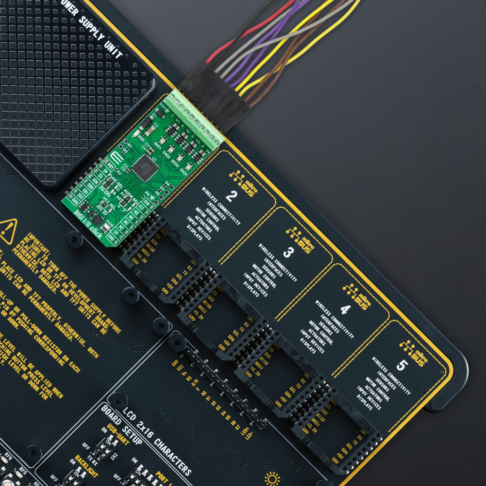
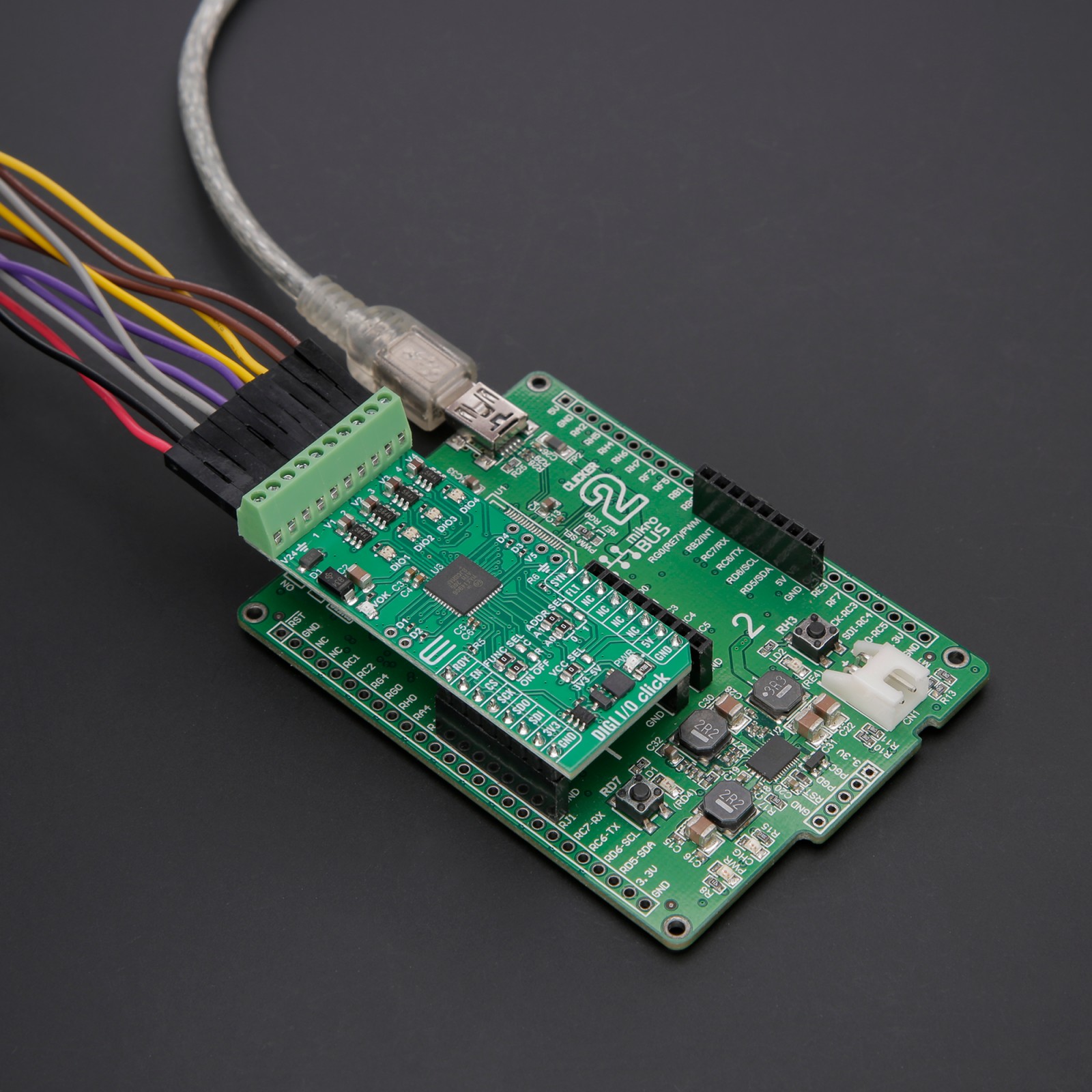
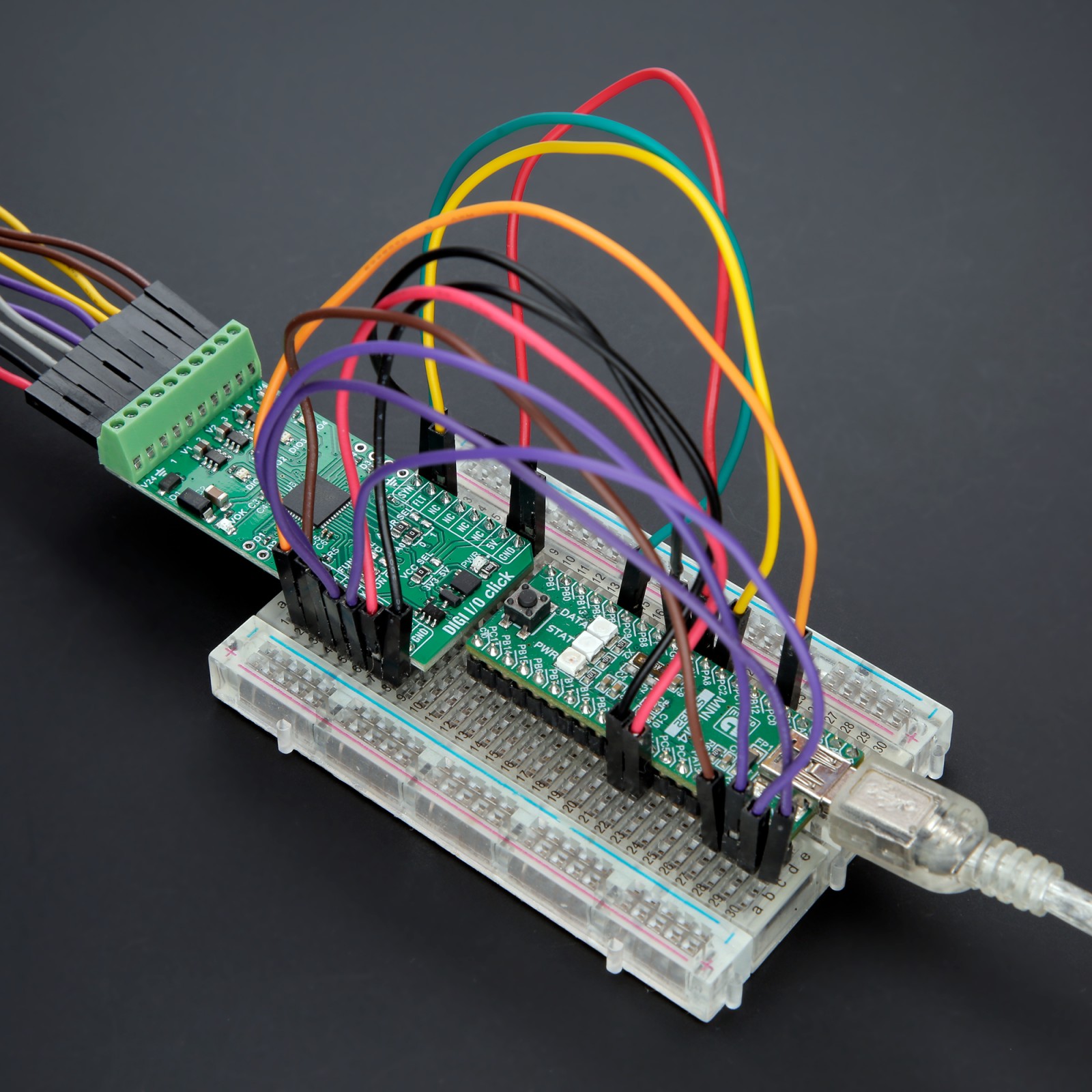
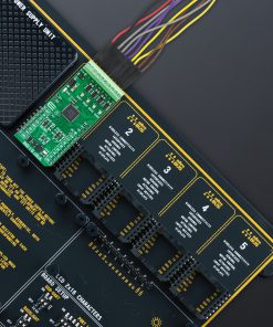
DIGI I/O Click is fully compatible with the mikroBUS™ socket and can be used on any host system supporting the mikroBUS™ standard. It comes with the mikroSDK open-source libraries, offering unparalleled flexibility for evaluation and customization. What sets this Click board™ apart is the groundbreaking ClickID feature, enabling your host system to seamlessly and automatically detect and identify this add-on board.
Stock: Lead-time applicable.
| 5+ | R793.25 |
| 10+ | R751.50 |
| 15+ | R709.75 |
| 20+ | R683.03 |
How does it work?
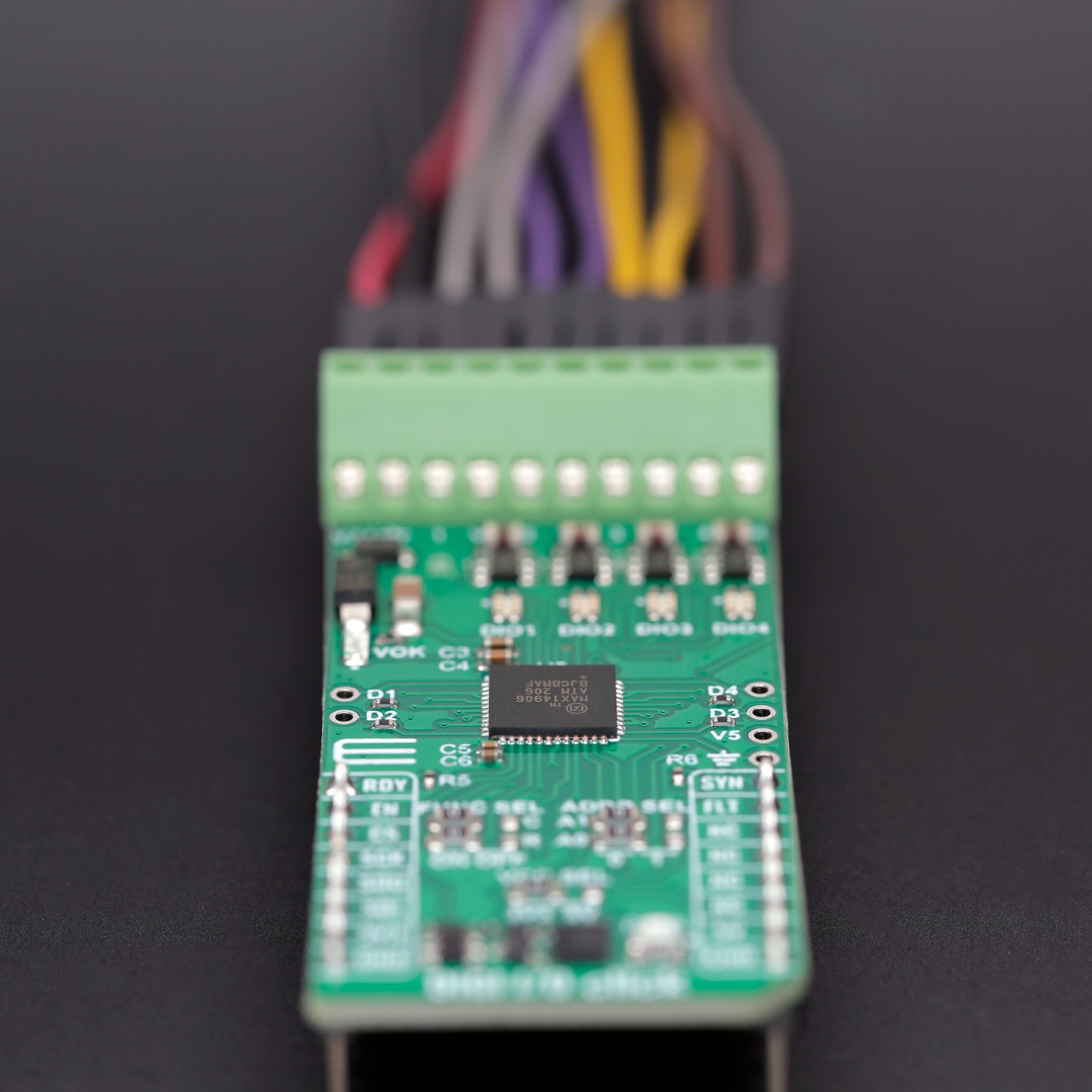
DIGI I/O Click is based on the MAX14906, a quad-channel industrial digital input/output IC from Analog Devices, designed to meet the IEC 61131-2 standards. This IC allows each of its four channels to be configured independently, making it an ideal solution for applications that require high-speed digital I/O flexibility. Each channel can function as a high-side switch, push-pull driver, or digital input that complies with Type 1, 2, or 3 standards. This Click board™ excels in environments where adaptable digital I/O functionality is critical, offering robust and reliable performance for complex industrial automation and control systems.

In output mode, the MAX14906 offers exceptional control, with high-side switch current limiting that can be adjusted between 130mA and 1.2A and an inrush current capability of up to twice the load current, ensuring reliable performance in demanding environments. The device also features an on-resistance of just 120mΩ at 25°C, allowing for efficient operation with minimal power loss. Additionally, the push-pull driver configuration enables high-speed signal transmission over cables, ensuring fast discharge of load capacitance for enhanced responsiveness. As a digital input device, the MAX14906 supports precise current sinking for various configurations, with 2.3mA for Type 1 and 3 inputs and 7mA for Type 2. This versatility makes DIGI I/O Click suitable for industrial digital input and output modules, motor control systems, Programmable Logic Controllers (PLC), and Distributed Control Systems (DCS).
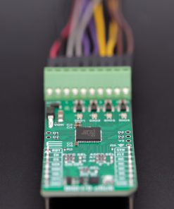
Each of the four DO/I channels (1-4 terminals at the top of the board) can be individually configured for digital output operation by setting the corresponding SetDi_ bit within the SetOUT register to 0. By default, all four channels initialize as outputs. Driving the EN pin HIGH activates the outputs for channels 1-4 while setting it LOW disables or three-states all outputs. Two DoMode bits in the ConfigDO register control the output mode for each channel, allowing selection between high-side or push-pull configurations. The Typ2Di bit in the ConfigDI register manages the input configuration mode, switching between Type 1 and 3 or Type 2 inputs. To control or read the I/O levels, users can either use the SPI interface or directly manage the four bidirectional logic pins (D1 to D4).
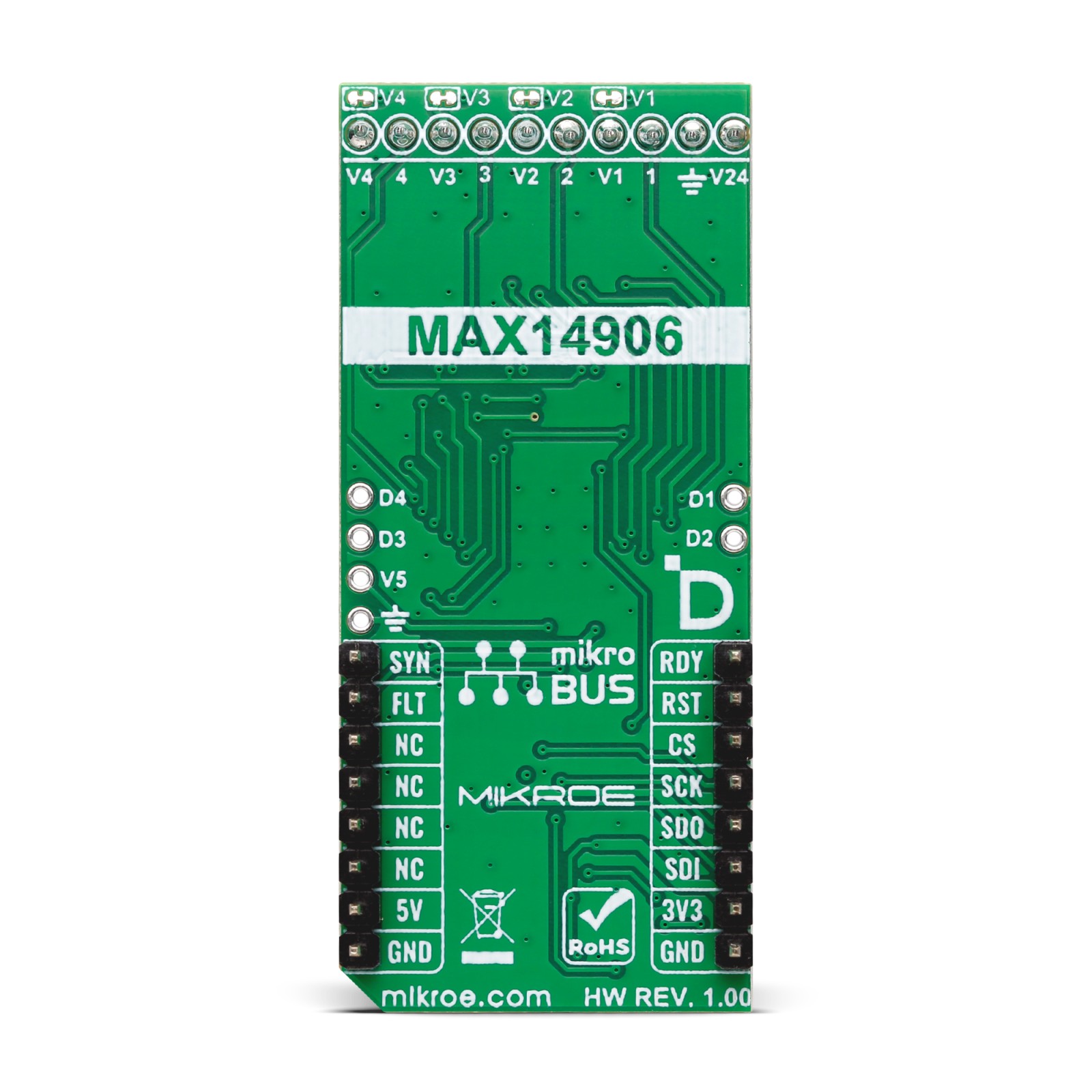
This Click board™ is designed for 24V operation, supplied through a terminal labeled V24. By default, all channels (1-4) are powered with 24V; however, each channel can be individually powered with different voltage values by connecting alternative voltages to the V1-V4 terminals. To enable this functionality, users must first cut the traces on the back of the board to disable the default power configuration. Additionally, the board includes a VOK green LED that indicates the presence of a valid external power supply.
The board communicates with the host MCU via an SPI interface with a maximum frequency of 10MHz. The SPI interface includes a built-in chip addressing decoder, enabling communication with multiple MAX14906-based boards using a shared SPI bus with a common chip select (CS) line. To support this, the board features a configurable SPI address that can be set using the ADDR SEL jumpers, allowing access to multiple MAX14906-based boards when used together. The SPI interface offers flexibility for global and per-channel configuration and diagnostics, including supply overvoltage and undervoltage detection, wire-break or open-wire detection, thermal overload protection, and current limit reporting.
In addition to the interface pins, the board uses several other control pins to ensure proper operation. The SYN pin serves as a synchronization control pin, where the terminals configured as digital outputs are updated simultaneously on the rising edge of SYN, and the output states of terminals 1-4 remain unchanged when SYN is held LOW. The RDY pin is passive LOW when the internal logic supply is above the undervoltage lockout (UVLO) threshold, indicating that the registers have adequate supply voltage. If the internal register supply drops below the UVLO threshold, the register contents are lost, and the RDY pin transitions to HIGH. Additionally, the FLT pin is asserted LOW when a diagnostic fault is detected on any of the channels. This pin can work with four LED indicators, a combination of red and green LEDs, indicating per-channel fault status and supply undervoltage conditions.
An additional feature is provided through the FUNC SEL jumper, which controls two functions. The upper C jumper serves as the CRC enable jumper, activating CRC on the SPI interface. The R jumper allows for the use of an external 5V regulator. When the R jumper is set to ON, the internal LDO regulator is disabled, and 5V must be supplied through the V5 header. If the R jumper is in the OFF position, the internal LDO remains active, and the V5 header functions as a 5V supply output.
This Click board™ can operate with either 3.3V or 5V logic voltage levels selected via the VCC SEL jumper. This way, both 3.3V and 5V capable MCUs can use the communication lines properly. Also, this Click board™ comes equipped with a library containing easy-to-use functions and an example code that can be used as a reference for further development.
Specifications
Type
Port expander
Applications
Ideal for industrial automation, motor control systems, PLCs, and Distributed Control Systems (DCS)
On-board modules
MAX14906 – quad-channel industrial digital input/output IC from Analog Devices
Key Features
Quad-channel digital input/output configuration, IEC 61131-2 compliant, adjustable high-side switch current limiting, fast signal transmission, supports 24V operation, built-in diagnostics, SPI interface, synchronization control, status indication and fault detection, and more
Interface
SPI
Feature
ClickID
Compatibility
mikroBUS™
Click board size
L (57.15 x 25.4 mm)
Input Voltage
3.3V or 5V,External
Pinout diagram
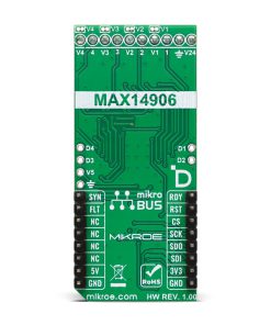
This table shows how the pinout on DIGI I/O Click corresponds to the pinout on the mikroBUS™ socket (the latter shown in the two middle columns).
Onboard settings and indicators
| Label | Name | Default | Description |
|---|---|---|---|
| LD1 | PWR | – | Power LED Indicator |
| LD2 | VOK | – | Valid External Power Supply LED Indicator |
| LD3-LD6 | DIO1-DIO4 | – | Channel Status LED Indicators |
| JP1 | VCC SEL | Left | Power Voltage Level Selection 3V3/5V: Left position 3V3, Right position 5V |
| JP2 | FUNC SEL – C | Left | CRC Enable Selection ON/OFF: Left position ON, Right position OFF |
| JP3-JP4 | ADDR SEL | Left | SPI Address Selection 0/1: Left position 0, Right position 1 |
| JP5 | FUNC SEL – R | Left | Regulator Enable Selection ON/OFF: Left position ON, Right position OFF |
| JP6-JP9 | V1-V4 | Connected | Default Power Configuration Cut Traces |
DIGI I/O Click electrical specifications
| Description | Min | Typ | Max | Unit |
|---|---|---|---|---|
| Supply Voltage | 3.3 | – | 5 | V |
| External Power Supply | – | 24 | – | V |
| High-Side Switch Current Limit | 0.130 | – | 1.2 | A |
Software Support
We provide a library for the DIGI IO Click as well as a demo application (example), developed using MIKROE compilers. The demo can run on all the main MIKROE development boards.
Package can be downloaded/installed directly from NECTO Studio Package Manager (recommended), downloaded from our LibStock™ or found on MIKROE github account.
Library Description
This library contains API for DIGI IO Click driver.
Key functions
-
digiio_write_regThis function writes data to the selected register by using SPI serial interface. -
digiio_read_regThis function reads data from the selected register by using SPI serial interface. -
digiio_sync_ioThis function synchronizes registers by toggling the SYNC pin logic state.
Example Description
This example demonstrates the use of DIGI I/O Click by setting and reading the DOI channels state.
void application_task ( void )
 {
     uint8_t set_out = 0;
     uint8_t doi_level = 0;
     digiio_sync_io ( &digiio );
     if ( DIGIIO_OK == digiio_read_reg ( &digiio, DIGIIO_REG_SET_OUT, &set_out ) )
     {
         set_out ^= ( DIGIIO_SET_OUT_HIGH_O1_MASK | DIGIIO_SET_OUT_HIGH_O2_MASK );
         if ( DIGIIO_OK == digiio_write_reg ( &digiio, DIGIIO_REG_SET_OUT, set_out ) )
         {
             digiio_sync_io ( &digiio );
         }
     }
     if ( DIGIIO_OK == digiio_read_reg ( &digiio, DIGIIO_REG_DOI_LEVEL, &doi_level ) )
     {
         if ( doi_level & DIGIIO_DOI_LEVEL_DOI1 )
         {
             log_printf ( &logger, " DOI1: HIGHrn" );
         }
         else
         {
             log_printf ( &logger, " DOI1: LOWrn" );
         }
         if ( doi_level & DIGIIO_DOI_LEVEL_DOI2 )
         {
             log_printf ( &logger, " DOI2: HIGHrn" );
         }
         else
         {
             log_printf ( &logger, " DOI2: LOWrn" );
         }
         if ( doi_level & DIGIIO_DOI_LEVEL_DOI3 )
         {
             log_printf ( &logger, " DOI3: HIGHrn" );
         }
         else
         {
             log_printf ( &logger, " DOI3: LOWrn" );
         }
         if ( doi_level & DIGIIO_DOI_LEVEL_DOI4 )
         {
             log_printf ( &logger, " DOI4: HIGHrn" );
         }
         else
         {
             log_printf ( &logger, " DOI4: LOWrn" );
         }
         log_printf ( &logger, "rn" );
     }
     Delay_ms ( 1000 );
 }
The full application code, and ready to use projects can be installed directly from NECTO Studio Package Manager (recommended), downloaded from our LibStock™ or found on MIKROE github account.
Other MIKROE Libraries used in the example:
- MikroSDK.Board
- MikroSDK.Log
- Click.DIGIIO
Additional notes and informations
Depending on the development board you are using, you may need USB UART click, USB UART 2 Click or RS232 Click to connect to your PC, for development systems with no UART to USB interface available on the board. UART terminal is available in all MIKROE compilers.
mikroSDK
This Click board™ is supported with mikroSDK – MIKROE Software Development Kit. To ensure proper operation of mikroSDK compliant Click board™ demo applications, mikroSDK should be downloaded from the LibStock and installed for the compiler you are using.
For more information about mikroSDK, visit the official page.
Resources
Downloads
| Weight | 23 g |
|---|---|
| Brand | MikroElektronika |

