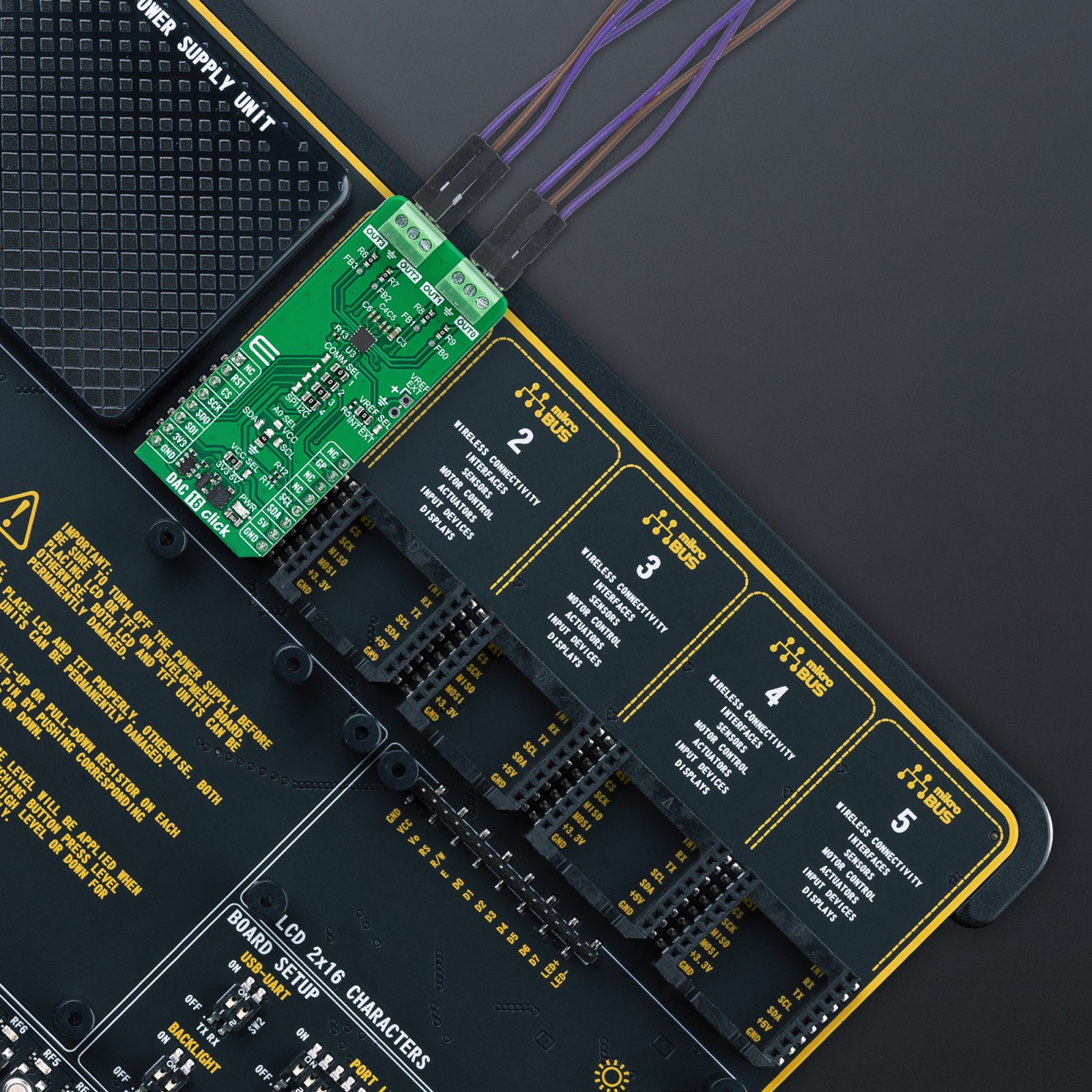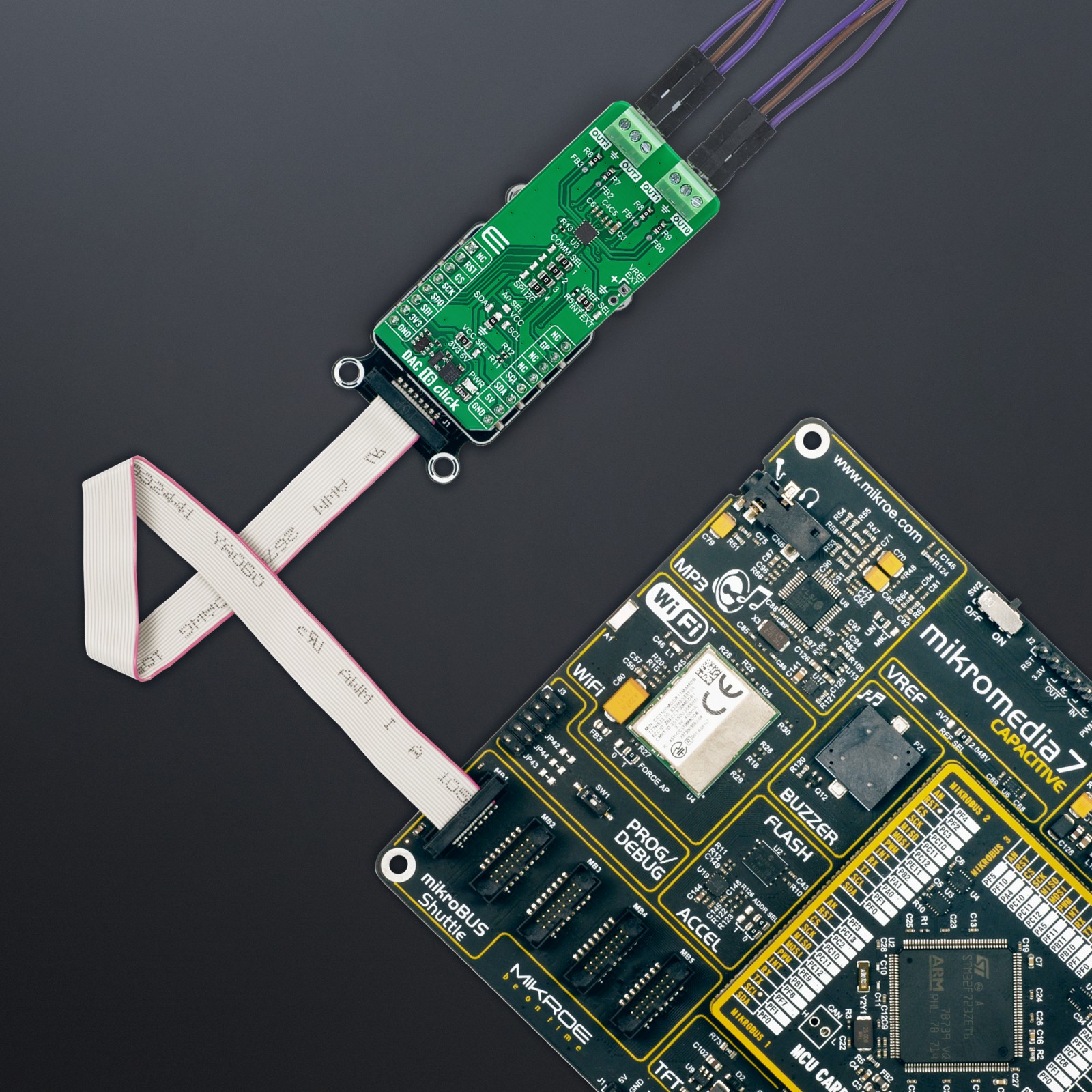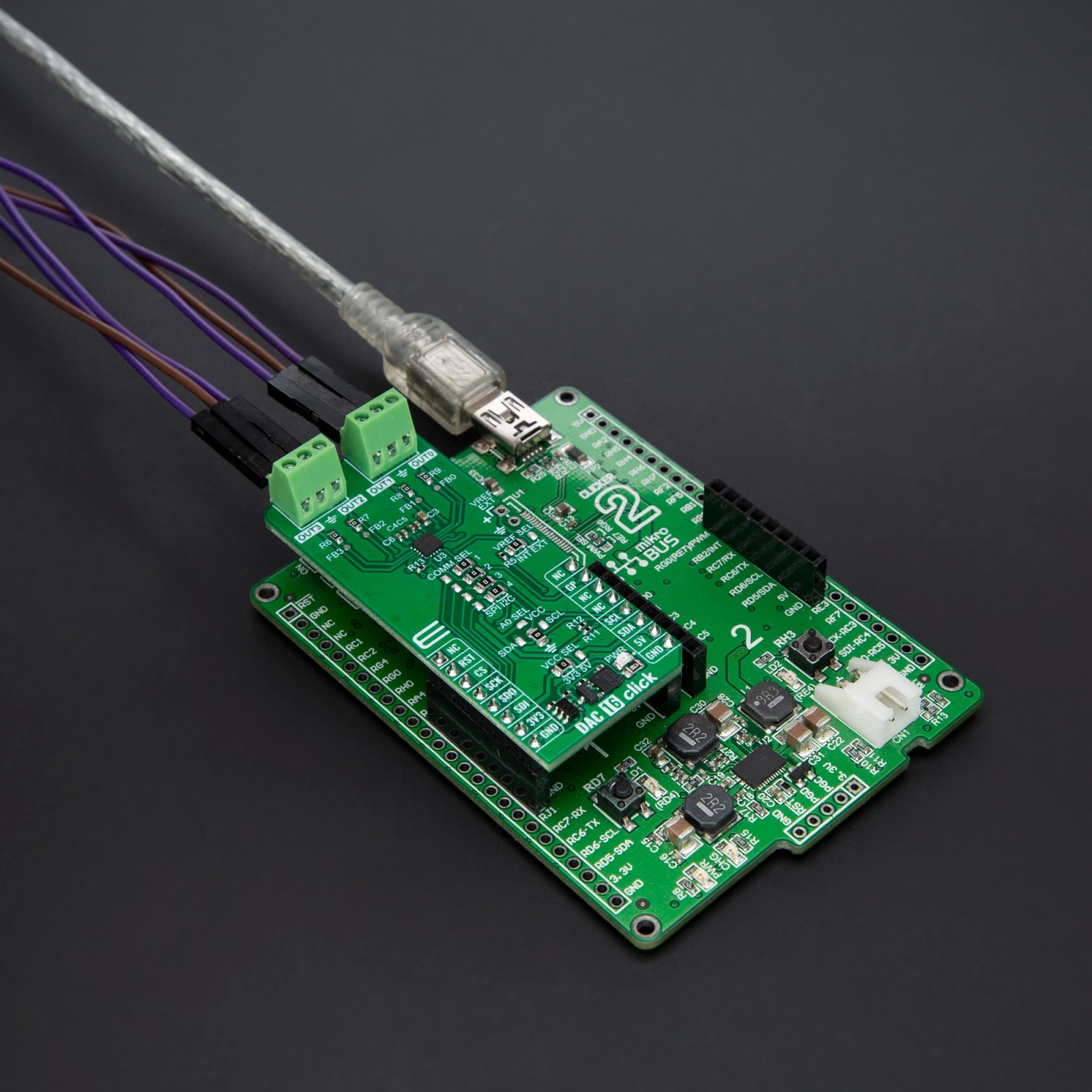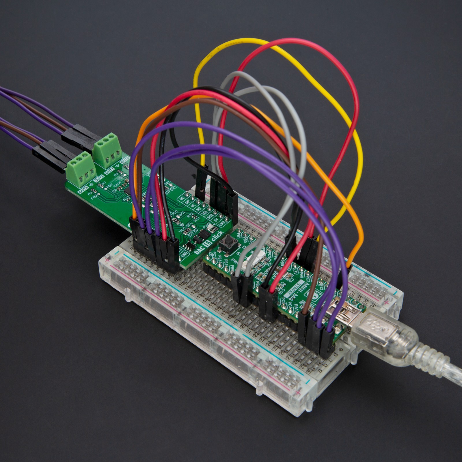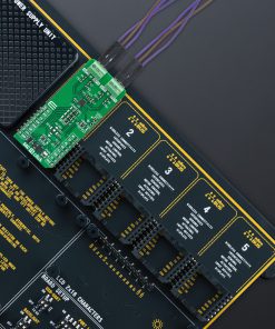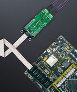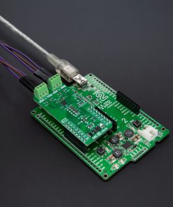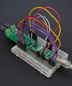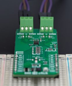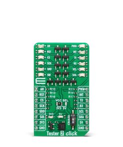
How does it work?
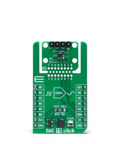
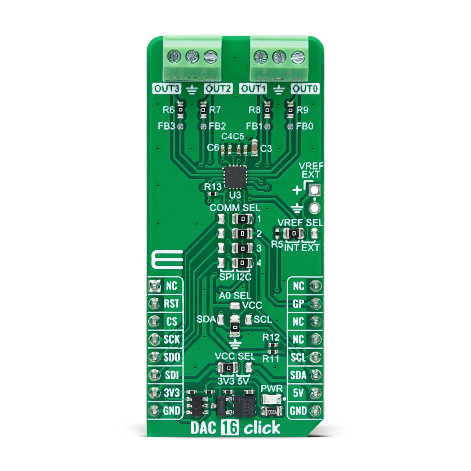
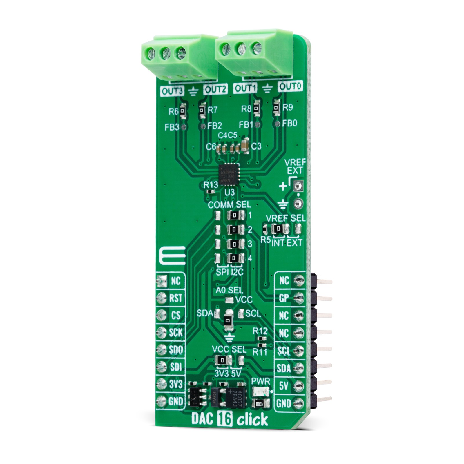
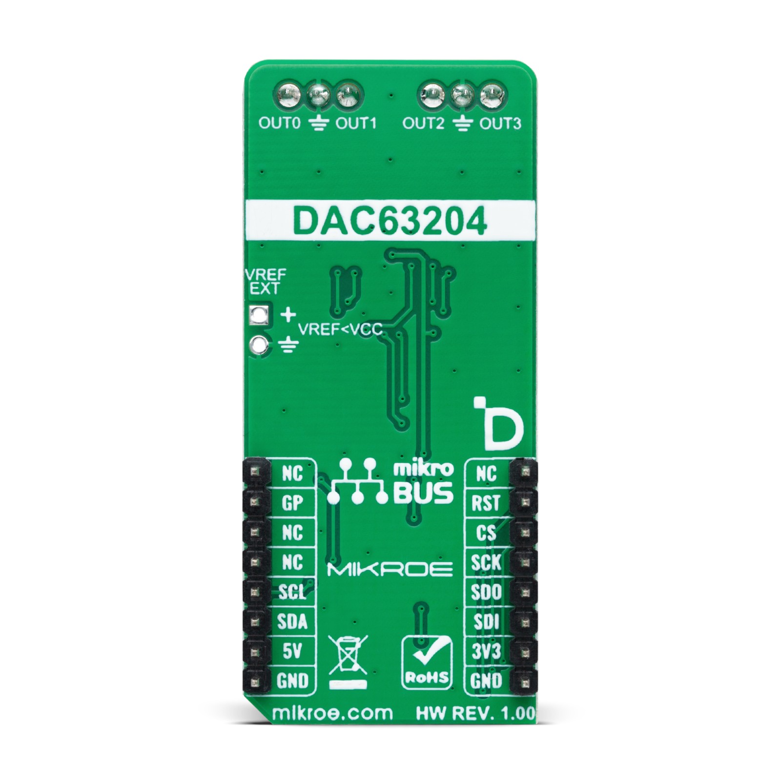
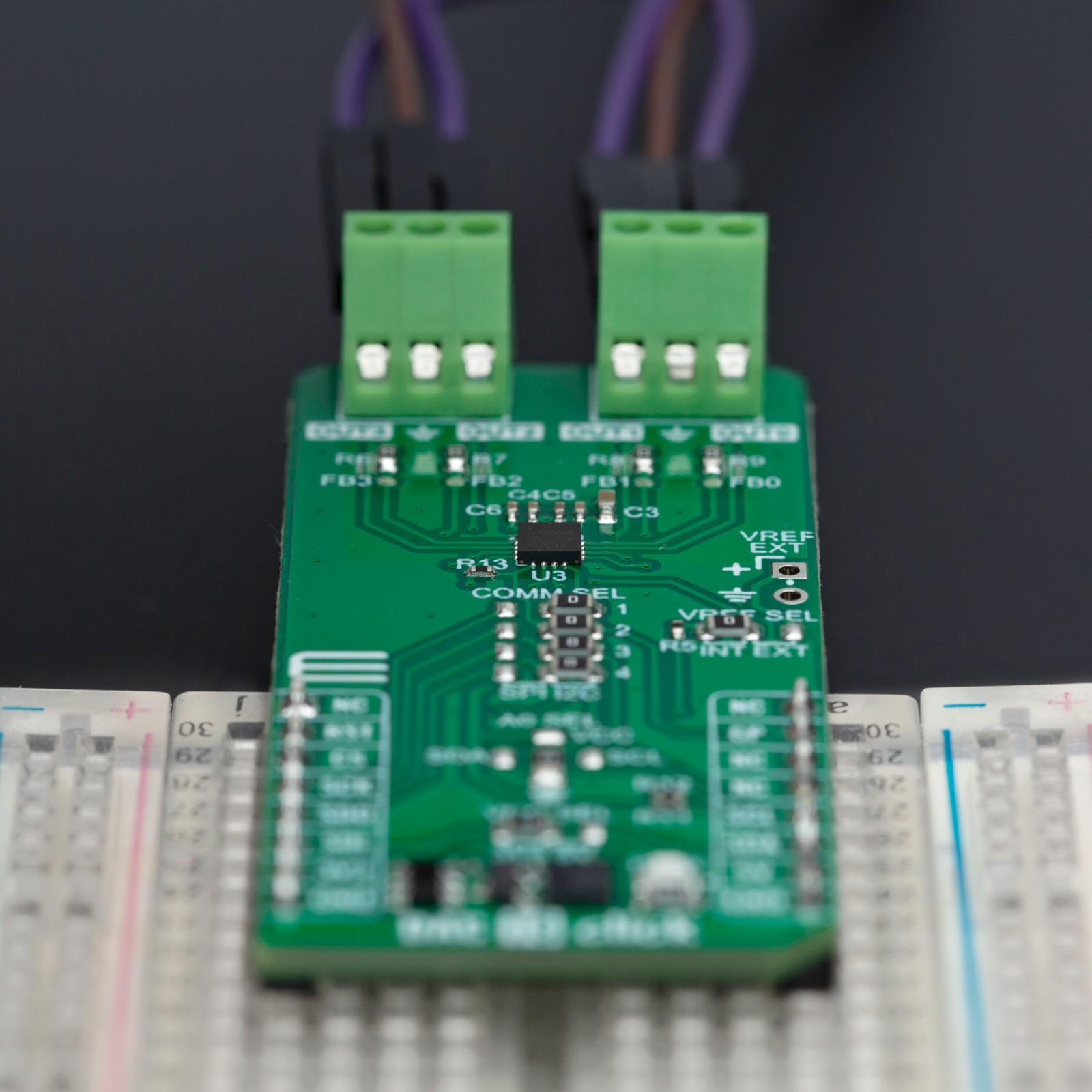
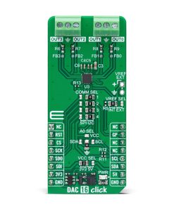
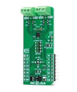
DAC 16 Click is based on the DAC63204-Q1, a highly reliable, automotive-qualified, quad-channel, buffered digital-to-analog converter (DAC) from Texas Instruments. This 12-bit DAC is versatile, providing both voltage and current outputs, making it ideal for various applications such as voltage margining and scaling, DC set-point biasing and calibration, and waveform generation. One of its key features is the Hi-Z power-down mode, which ensures that the outputs maintain a high-impedance state during power-off conditions, offering additional protection and minimizing power consumption.
The DAC63204-Q1 supports flexible configuration of its output channels (OUT0-OUT3). For voltage outputs, it provides a 1LSB differential non-linearity (DNL) and allows for adjustable gains, with options of 1x, 1.5x, 2x, 3x, and 4x. For current outputs, it offers a range of ±25μA to ±250μA, with 1LSB integral non-linearity (INL) and DNL (8-bit), making it suitable for precision applications requiring fine control over current delivery.
This DAC can operate using either an internal reference, an external reference (selectable via an unpopulated VREF EXT header), or the power supply itself as the reference. The full-scale output can range from 1.8V to 5V, depending on the reference source. Selection between the internal and external voltage reference is easily managed by positioning the VREF SEL jumper to either the INT or EXT position.
Communication with the host MCU is made through either a 4-wire SPI or I2C interface. The SPI interface supports clock frequencies up to 50MHz, while the I2C interface operates up to 1MHz. The desired communication protocol can be selected via the four COMM SEL jumpers, with the I2C interface being set as the default. Additionally, the I2C interface allows for flexible address configuration using the ADDR SEL jumper, offering four selectable I2C addresses (with 0x48 set by default).
Beyond communication, DAC 16 Click also provides a general-purpose I/O (GP) pin, which is highly configurable for various functions, such as serving as an SDO pin, LDAC, power-down (PD), status indicator, protection, fault dump, or reset. The specific function of the GP pin can be configured through the register map and programmed into non-volatile memory (NVM) for persistent settings.
This Click board™ can operate with either 3.3V or 5V logic voltage levels selected via the VCC SEL jumper. This way, both 3.3V and 5V capable MCUs can use the communication lines properly. Also, this Click board™ comes equipped with a library containing easy-to-use functions and an example code that can be used as a reference for further development.
Specifications
Type
DAC
Applications
Ideal for voltage margining, DC biasing and calibration, and waveform generation
On-board modules
DAC63204-Q1 – quad-channel, buffered digital-to-analog converter (DAC) from Texas Instruments
Key Features
12-bit quad-channel DAC, AEC-Q100 qualified, flexible output configuration (gain and current range), Hi-Z power-down modes, multiple reference options, dual communication interfaces, configurable general-purpose I/O pin, and more
Interface
I2C,SPI
Feature
ClickID
Compatibility
mikroBUS™
Click board size
L (57.15 x 25.4 mm)
Input Voltage
3.3V or 5V
Pinout diagram
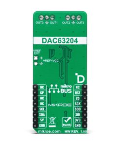
This table shows how the pinout on DAC 16 Click corresponds to the pinout on the mikroBUS™ socket (the latter shown in the two middle columns).
Onboard settings and indicators
Label | Name | Default | Description |
---|---|---|---|
LD1 | PWR | – | Power LED Indicator |
JP1 | VCC SEL | Left | Power Voltage Level Selection 3V3/5V: Left position 3V3, Right position 5V |
JP2-JP5 | COMM SEL | Right | Communication Interface Selection SPI/I2C: Left position SPI, Right position I2C |
JP6 | VREF SEL | Left | Voltage Reference Source Selection INT/EXT: Left position INT, Right position EXT |
JP7 | ADDR SEL | Lower | I2C Address Selection VCC/SDA/GND/SCL: Upper position VCC, Left position SDA, Lower position GND, Right position SCL |
DAC 16 Click electrical specifications
Description | Min | Typ | Max | Unit |
---|---|---|---|---|
Supply Voltage | 3.3 | – | 5 | V |
External Power Supply | 1.8 | – | 5 | V |
Output Current | ±25 | – | ±250 | μA |
Resolution | – | 12 | – | bit |
Software Support
We provide a library for the DAC 16 Click as well as a demo application (example), developed using MIKROE compilers. The demo can run on all the main MIKROE development boards.
Package can be downloaded/installed directly from NECTO Studio Package Manager (recommended), downloaded from our LibStock™ or found on MIKROE github account.
Library Description
This library contains API for DAC 16 Click driver.
Key functions
-
dac16_set_dac_data
This function sets the raw DAC data for the selected DAC channel. -
dac16_start_function_gen
This function starts the function generator for the selected DAC channel. -
dac16_stop_function_gen
This function stops the function generator for the selected DAC channel.
Example Description
This example demonstrates the use of DAC 16 Click board™ by changing the voltage level on the OUT0 as well as the waveform signals from a function generator on the OUT1.
void application_task ( void )
{
static uint16_t dac = 0;
static uint8_t waveform = DAC16_WAVEFORM_TRIANGULAR;
if ( DAC16_OK == dac16_set_dac_data ( &dac16, DAC16_SEL_DAC_0, dac ) )
{
log_printf( &logger, "rn OUT0: %u -> %.2f Vrn",
dac, ( float ) dac * DAC16_VDD_3V3 / DAC16_DAC_DATA_MAX );
dac += 100;
if ( dac > DAC16_DAC_DATA_MAX )
{
dac = DAC16_DAC_DATA_MIN;
}
}
err_t error_flag = dac16_stop_function_gen ( &dac16, DAC16_SEL_DAC_1 );
error_flag |= dac16_config_function_gen ( &dac16, DAC16_SEL_DAC_1, waveform,
DAC16_CODE_STEP_32_LSB, DAC16_SLEW_RATE_4_US );
error_flag |= dac16_start_function_gen ( &dac16, DAC16_SEL_DAC_1 );
if ( DAC16_OK == error_flag )
{
log_printf( &logger, " OUT1: " );
switch ( waveform )
{
case DAC16_WAVEFORM_TRIANGULAR:
{
log_printf( &logger, "triangular wave at about 1kHzrn" );
waveform = DAC16_WAVEFORM_SAWTOOTH;
break;
}
case DAC16_WAVEFORM_SAWTOOTH:
{
log_printf( &logger, "sawtooth wave at about 2kHzrn" );
waveform = DAC16_WAVEFORM_INV_SAWTOOTH;
break;
}
case DAC16_WAVEFORM_INV_SAWTOOTH:
{
log_printf( &logger, "inverse sawtooth wave at about 2kHzrn" );
waveform = DAC16_WAVEFORM_SINE;
break;
}
case DAC16_WAVEFORM_SINE:
{
log_printf( &logger, "sine wave at about 10.5kHzrn" );
waveform = DAC16_WAVEFORM_DISABLE;
break;
}
case DAC16_WAVEFORM_DISABLE:
{
log_printf( &logger, "function generator disabledrn" );
waveform = DAC16_WAVEFORM_TRIANGULAR;
break;
}
default:
{
log_printf( &logger, "unknown statern" );
break;
}
}
// OUT2 and OUT3 are set in dac16_default_cfg
log_printf( &logger, " OUT2: sine wave at about 10.5kHzrn" );
log_printf( &logger, " OUT3: sawtooth wave at about 2kHzrn" );
}
Delay_ms ( 1000 );
Delay_ms ( 1000 );
Delay_ms ( 1000 );
}
The full application code, and ready to use projects can be installed directly from NECTO Studio Package Manager (recommended), downloaded from our LibStock™ or found on MIKROE github account.
Other MIKROE Libraries used in the example:
- MikroSDK.Board
- MikroSDK.Log
- Click.DAC16
Additional notes and informations
Depending on the development board you are using, you may need USB UART click, USB UART 2 Click or RS232 Click to connect to your PC, for development systems with no UART to USB interface available on the board. UART terminal is available in all MIKROE compilers.
mikroSDK
This Click board™ is supported with mikroSDK – MIKROE Software Development Kit. To ensure proper operation of mikroSDK compliant Click board™ demo applications, mikroSDK should be downloaded from the LibStock and installed for the compiler you are using.
For more information about mikroSDK, visit the official page.