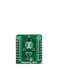
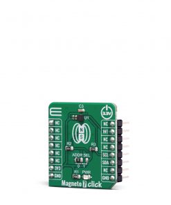
Magneto 7 Click
R355.00 ex. VAT
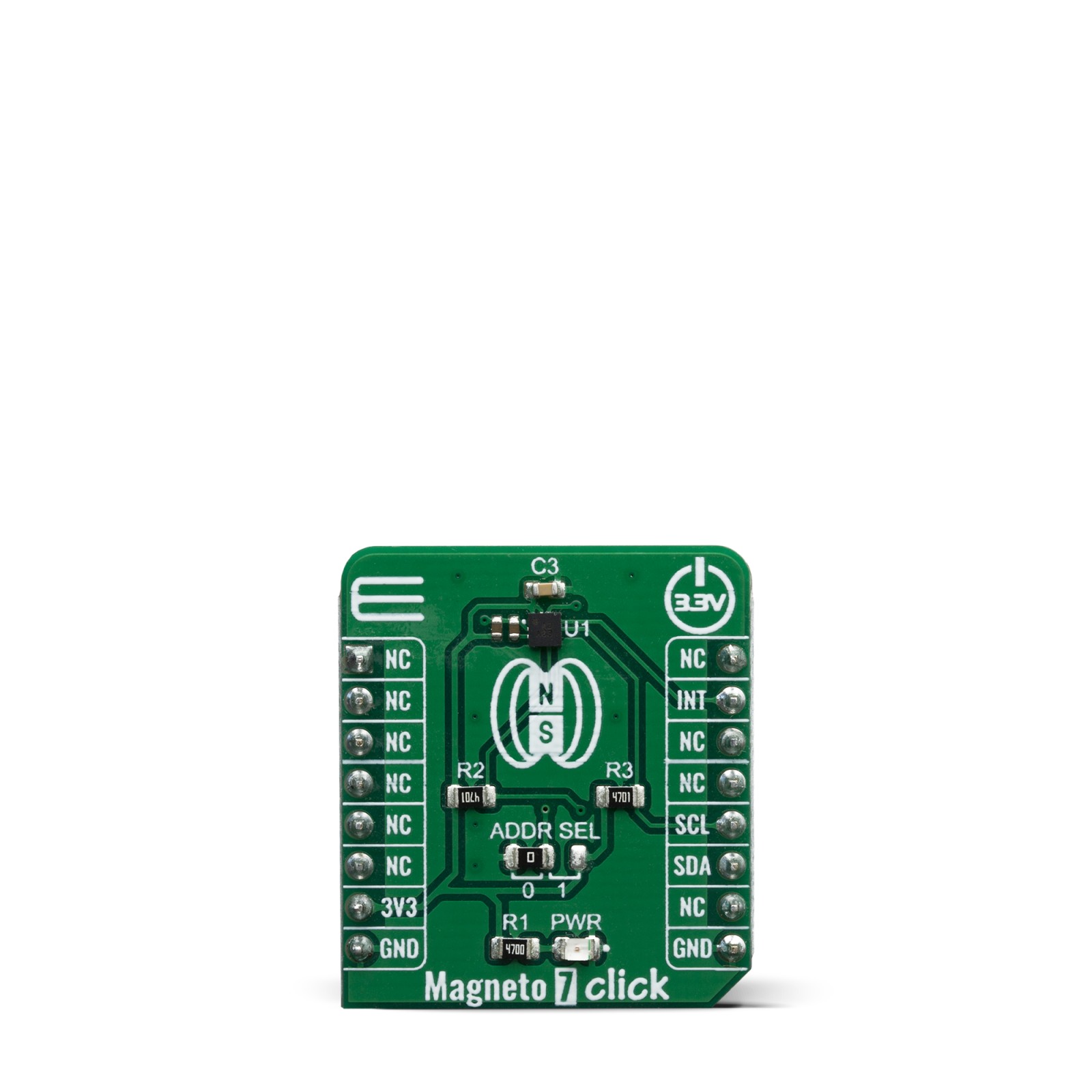
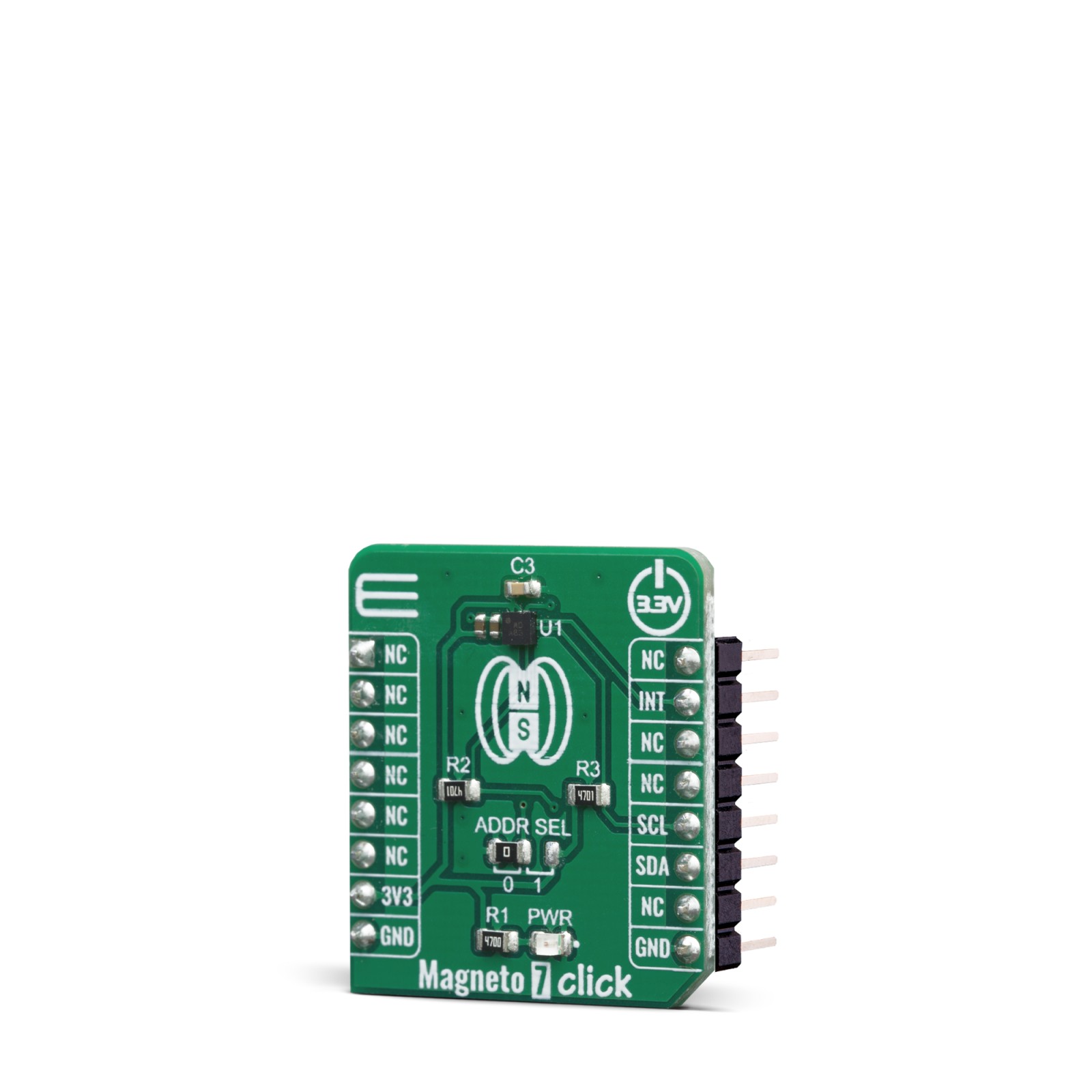
Magneto 7 Click is a high-resolution magnetic sensor Click board™ which allows contactless orientation sensing. It features the BM1422AGMV, a complete integrated solution with magneto-impedance (MI) elements, low-noise analog AD converter, and digital signal processing (DSP) sections, on the same die. Thanks to the internal DSP processing, the BM1422AGMV can output the absolute movement detection over the serial interface as a bit stream. The BM1422AGMV IC is ideal for using in various applications, such as wristwatches, smartphones, tablets, etc.
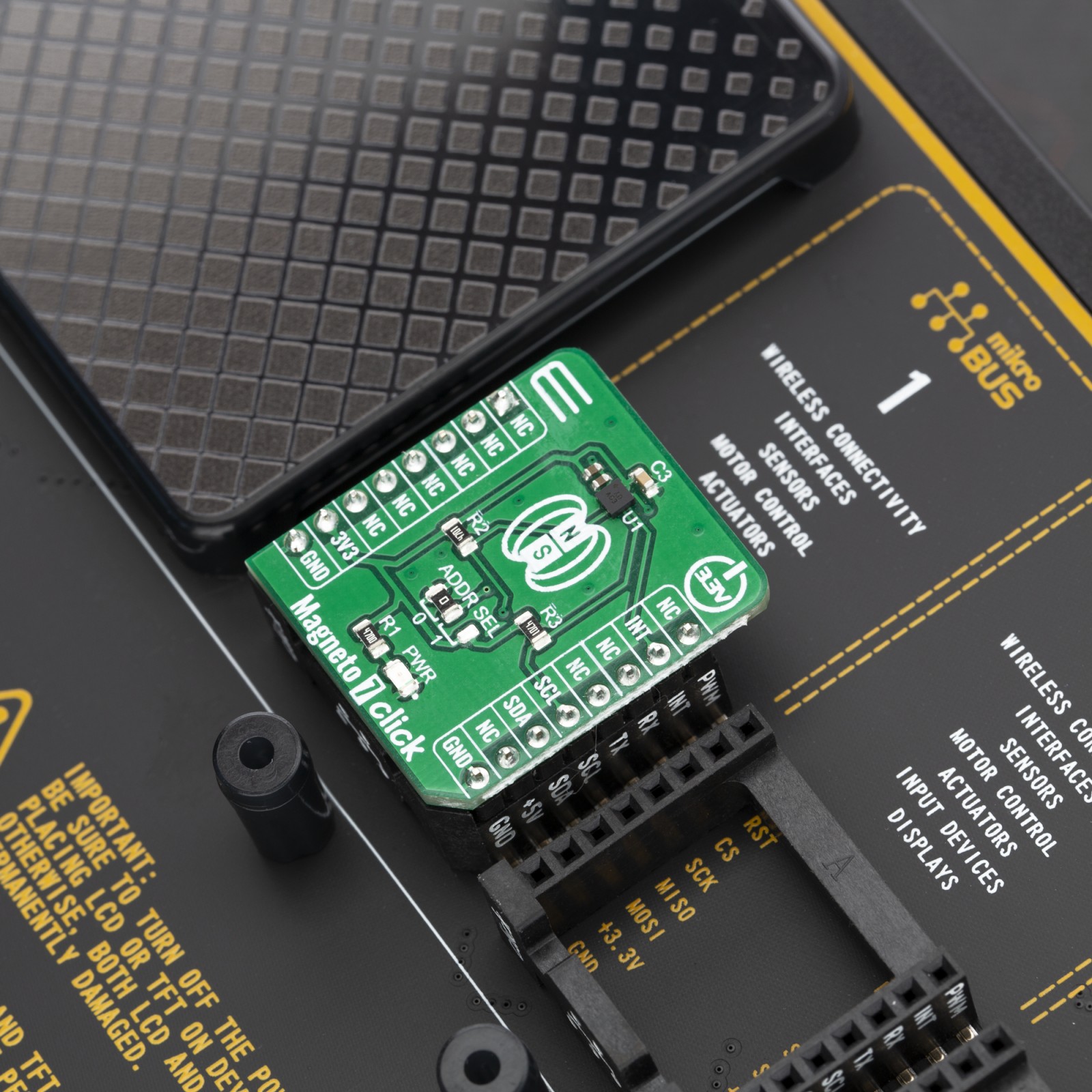
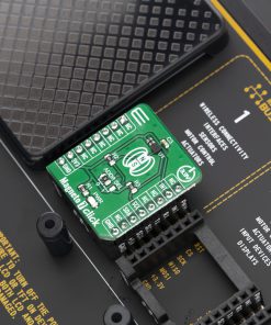
Magneto 7 click is supported by a mikroSDK compliant library, which includes functions that simplify software development. This Click board™ comes as a fully tested product, ready to be used on a system equipped with the mikroBUS™ socket.
Stock: Lead-time applicable.
| 5+ | R337.25 |
| 10+ | R319.50 |
| 15+ | R301.75 |
| 20+ | R290.39 |
Magneto 7 click is a very accurate and reliable magnetic sensor device, which features the BM1422AGMV, a 3-axis magnetic sensor IC from ROHM Semiconductor. The BM1422AGMV IC features an onboard signal processing and I2C communication, simplifying the application development and reducing the host MCU load. It is a very accurate sensor, which can sense the magnetic field with the precision of 0.042μT, with the full scale magnetic field detection of ±1200μT. Featuring onboard signal processing, fast I2C communication, low power consumption, and high precision with the low noise, this Click board™ is an ideal solution for developing portable electronic compass applications, but it is not limited only to directional measurement. It can be also used for the detection of a magnetic field, vehicle detection, and similar applications that rely on an accurate magnetic field sensing in all three axes.
How does it work?
This Click board™ uses the BM1422AGMV, a 3-axis magnetic sensor IC from ROHM Semiconductor. This sensor incorporates magneto-impedance (MI) elements to detect magnetic field and a control IC in a small package. The magneto-impedance (MI) effect is a phenomenon in which the voltage induced by a high frequency current source in a ferromagnetic wire changes with the application of an external field. Just like a global positioning system (GPS) is effective for detecting the position, a magnetic sensor is usable for detecting the orientation of the user, and therefore simplify the development of motion tracking applications.
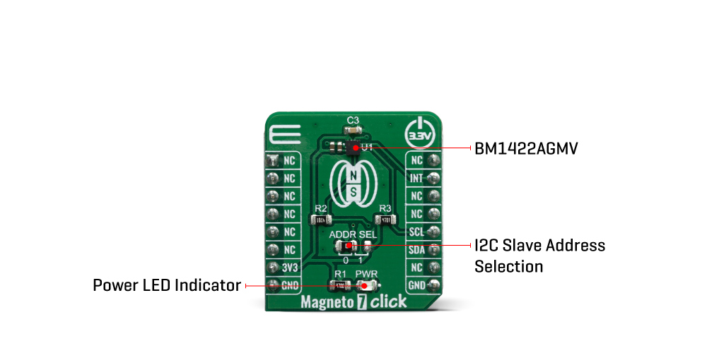
The resulting characteristics of this sensor IC, are impressive: it have measurable range of ±1200μT, a sensitivity of 0.042μT/LSB when using 14 bit ADC mode, and can be exposed to maximum 1000mT field. The Status register offers the status indication of the measured data. This, DRDY bit, is output to inform the preparation status of the measured data and is routed to the INT pin of the Click board™.
This Click Board™ uses I2C, and it is designed to be operated only with 3.3V logic level. A proper logic voltage level conversion should be performed before the Click board™ is used with MCUs with logic levels of 5V.
Specifications
Type
Magnetic
Applications
It is an ideal solution for developing portable electronic compass applications, but it can be also used for the detection of a magnetic field, vehicle detection, and similar applications that rely on an accurate magnetic field sensing in all three axes.
On-board modules
BM1422AGMV, a 3-axis magnetic sensor IC from from ROHM Semiconductor.
Key Features
Accurate sensing of the magnetic field in all three axes, on-chip processing functions, 12bit / 14bit Digital Output
Interface
I2C
Feature
No ClickID
Compatibility
mikroBUS™
Click board size
S (28.6 x 25.4 mm)
Input Voltage
3.3V
Pinout diagram
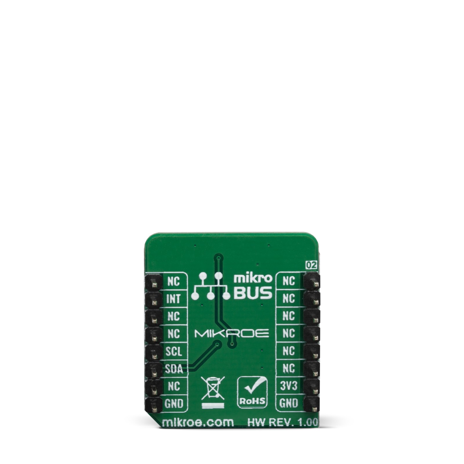
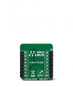
This table shows how the pinout on Magneto 7 click corresponds to the pinout on the mikroBUS™ socket (the latter shown in the two middle columns).
Onboard settings and indicators
| Label | Name | Default | Description |
|---|---|---|---|
| LD1 | PWR | – | Power LED Indicator |
| JP1 | ADDR SEL | Left | Slave I2C address LSB selection: left position 0, right position 1 |
Magneto 7 click electrical specifications
| Description | Min | Typ | Max | Unit |
|---|---|---|---|---|
| Magnetic field measurement range on each axis | -1200 | – | 1200 | μT |
| Magnetic Sensitivity | – 0.042 | – | 0.042 | μT |
| Operating Current (100SPS) | – | 0.15 | – | mA |
Software Support
We provide a library for the Magneto 7 click on our LibStock page, as well as a demo application (example), developed using MikroElektronika compilers. The demo can run on all the main MikroElektronika development boards.
Library Description
Library contains functions for getting temperature and humidity. Library contains functions for getting and setting user register. Library contains functions for changing resolution and soft reset. Library contains functions for enabling/disabling heater and OTP.
Key functions:
uint8_t magneto7_intGet( void )– returns INT pin state.void magneto7_get_data( int16_t * x_axis, int16_t * y_axis, int16_t * z_axis )– gets data register values and sorts thair content into signed 16bit values.float magneto7_convert_to_uT( int16_t raw_data, uint8_t sensor_resolution )– converts raw data by dividing raw data with 6 or 24 for 12bit or 14bit data.
Examples description
The application is composed of three sections :
- System Initialization – Initializes I2C module, LOG module and INT pin .
- Application Initialization – Initializes I2C driver and device .
- Application Task – Waits for INT pin to go LOW, gets raw data, converts it to uT and logs results.
void applicationTask( )
{
    int_status = magneto7_intGet( );

    if (int_status == 0)
    {
        magneto7_get_data( &data_x, &data_y, &data_z );

        converted_data = magneto7_convert_to_uT( data_x, _MAGNETO7_SENSOR_RES_14_BIT );
        FloatToStr( converted_data, text );
        magneto7_floatCut( );
        mikrobus_logWrite( "> X Axis : ", _LOG_TEXT );
        mikrobus_logWrite( text, _LOG_TEXT );
        mikrobus_logWrite( " [uT]", _LOG_LINE );

        converted_data = magneto7_convert_to_uT( data_y, _MAGNETO7_SENSOR_RES_14_BIT );
        FloatToStr( converted_data, text );
        magneto7_floatCut( );
        mikrobus_logWrite( "> Y Axis : ", _LOG_TEXT );
        mikrobus_logWrite( text, _LOG_TEXT );
        mikrobus_logWrite( " [uT]", _LOG_LINE );

        converted_data = magneto7_convert_to_uT( data_z, _MAGNETO7_SENSOR_RES_14_BIT );
        FloatToStr( converted_data, text );
        magneto7_floatCut( );
        mikrobus_logWrite( "> Z Axis : ", _LOG_TEXT );
        mikrobus_logWrite( text, _LOG_TEXT );
        mikrobus_logWrite( " [uT]", _LOG_LINE );

        mikrobus_logWrite( " ", _LOG_LINE );

        Delay_ms(300);
    }
}
Additional Functions :
- magneto7_floatCut() – Rounds float number converted to string to two decimals
The full application code, and ready to use projects can be found on our LibStock page.
Other Mikroe Libraries used in the example:
- I2C
- UART
- Conversions
Additional notes and informations
Depending on the development board you are using, you may need USB UART click, USB UART 2 click or RS232 click to connect to your PC, for development systems with no UART to USB interface available on the board. The terminal available in all MikroElektronika compilers, or any other terminal application of your choice, can be used to read the message.
mikroSDK
This Click board™ is supported with mikroSDK - MikroElektronika Software Development Kit. To ensure proper operation of mikroSDK compliant Click board™ demo applications, mikroSDK should be downloaded from the LibStock and installed for the compiler you are using.
For more information about mikroSDK, visit the official page.
Resources
Downloads
| Weight | 17 g |
|---|---|
| Brand | MikroElektronika |

