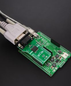
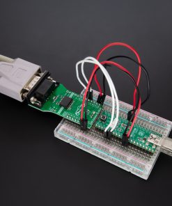
How does it work?
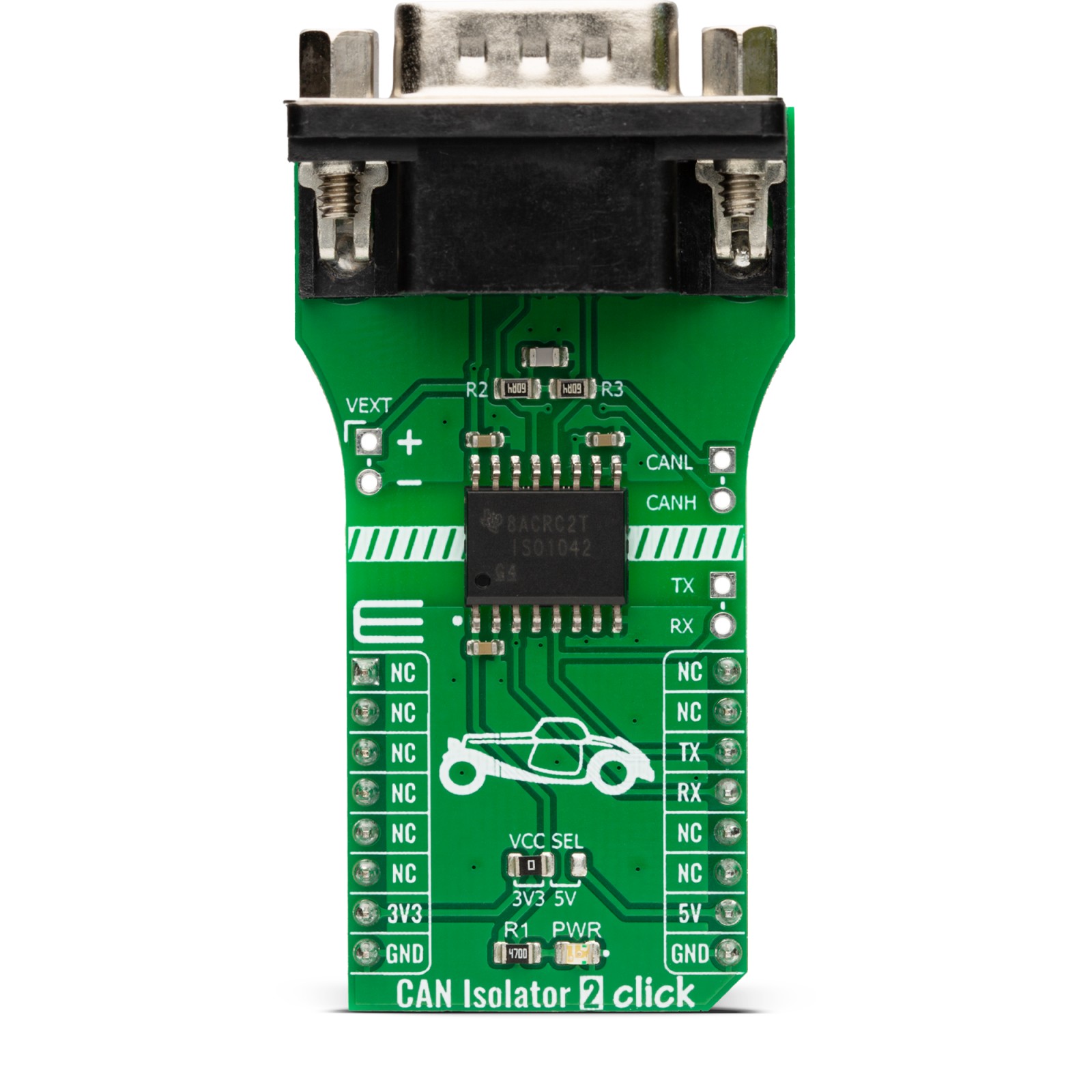
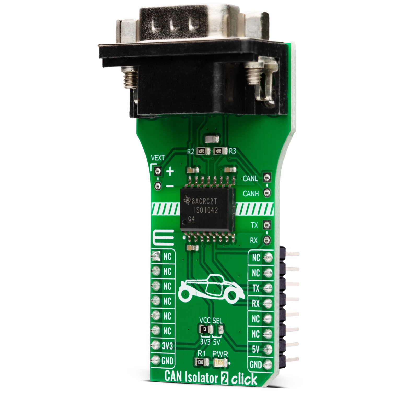
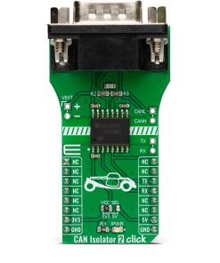
CAN Isolator 2 Click is based on the ISO1042, an isolated CAN transceiver from Texas Instruments. It has several features, such as undervoltage protection, driver Dominant Time Out (TXD DTO), HBM ESD tolerance on bus pins, and more. The transceiver has ideal passive high-impedance bus terminals when unpowered. If used in conjunction with the isolated power supplies, the CAN Isolator 2 Click can be the ideal choice for protection against high voltages and noise currents from the bus.
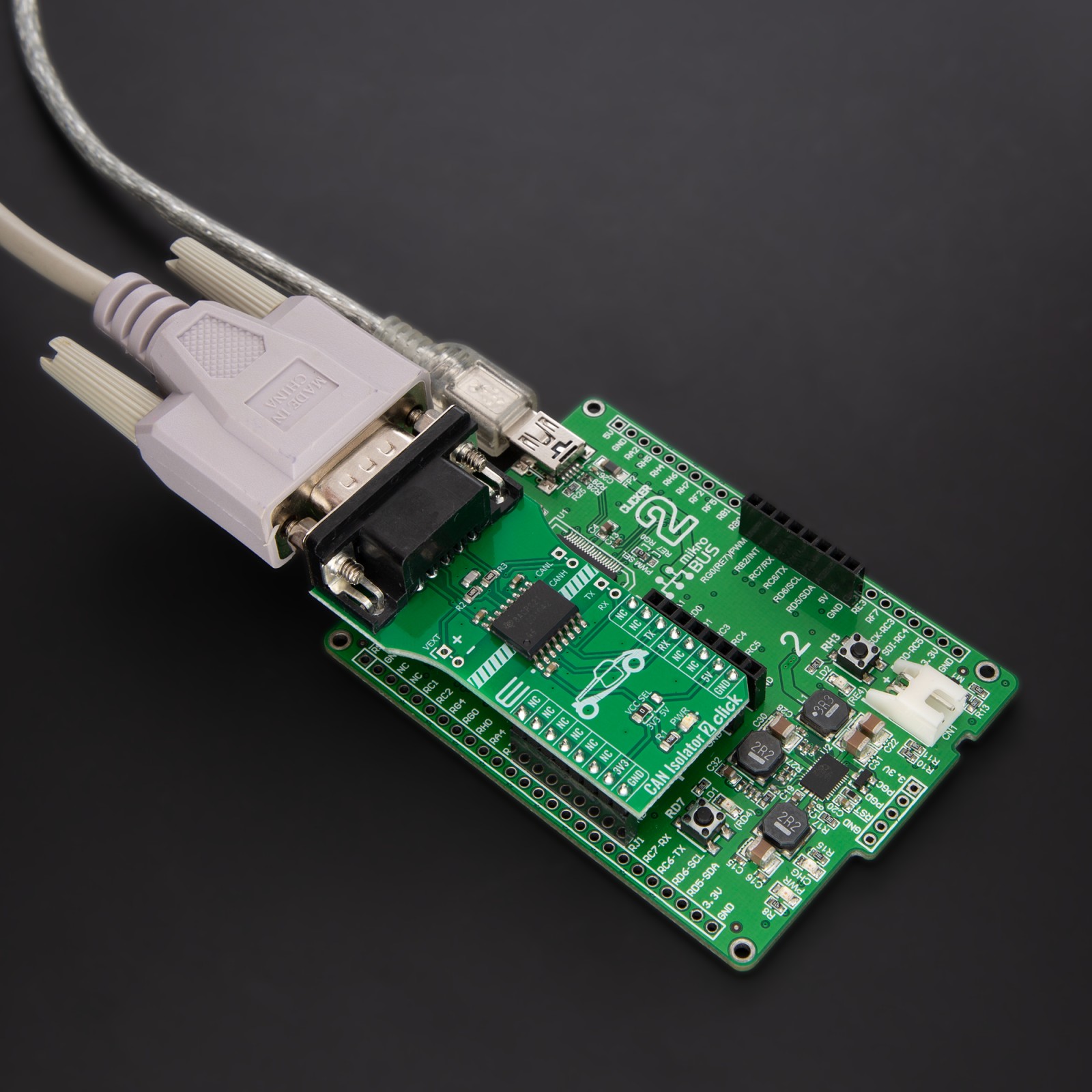
There are two states of operation on this Click board™: dominant and recessive. In a dominant state, the bus is driven differentially by a driver. In a recessive state, the host MCU of the CAN node uses the TXD pin to drive the bus and receives the data from the bus on the RXD pin. To connect ISO1042 on a CAN bus, this Click board™ features a standard DB 9-pin male connector. According to the ISO 11898-2 standard, a maximum bus length is 40m, and a maximum stub length is 0.3m, while with careful design, the cables could be longer. This transceiver has a high input impedance, thus allowing a large number of nodes on the CAN bus.
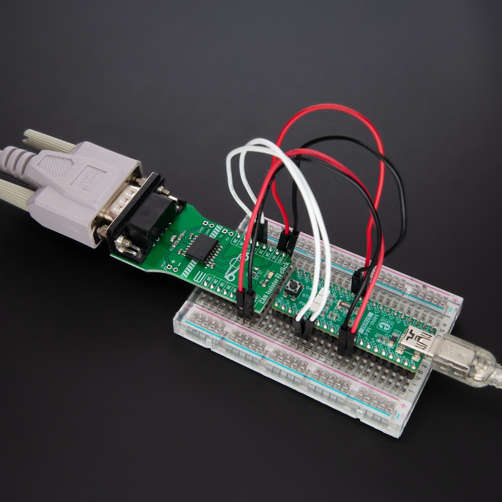
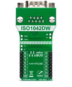
CAN Isolator 2 Click uses a standard UART interface to communicate with the host MCU, with commonly used UART RX and TX. In addition, there are few headers to interface lines directly with jumper wires. The left side of the CAN Isolator 2 Click has VEXT 2-pin header to connect the external power supply. Along with the VEXT, on the opposite side, there are CANH and CANL pins to interface the CAN bus in the same manner. Under the CAN header, there is also one TX and RX header which allows this Click board™ to be used independently of the host MCU.
This Click board™ can operate with either 3.3V or 5V logic voltage levels selected via the VCC SEL jumper. This way, both 3.3V and 5V capable MCUs can use the communication lines properly. However, the Click board™ comes equipped with a library containing easy-to-use functions and an example code that can be used, as a reference, for further development.
Specifications
Type
CAN,Isolators
Applications
Can be used for the development of solar inverters, AC and servo drives, industrial field networks, PLC and DCS communication modules, battery charging and management, and more
On-board modules
ISO1042 – isolated CAN transceiver from Texas Instruments
Key Features
The fully isolated interface between the CAN protocol controller and the physical layer bus, capable of running at data rates of up to 5Mbps, robust electromagnetic compatibility, ideal passive high impedance bus terminal when unpowered, long bus cable length, dominant and recessive states during operation, and more
Interface
UART
Feature
No ClickID
Compatibility
mikroBUS™
Click board size
L (57.15 x 25.4 mm)
Input Voltage
3.3V or 5V,External
Pinout diagram
This table shows how the pinout on CAN Isolator 2 Click corresponds to the pinout on the mikroBUS™ socket (the latter shown in the two middle columns).
Onboard settings and indicators
Label | Name | Default | Description |
---|---|---|---|
LD1 | PWR | – | Power LED Indicator |
JP1 | VCC SEL | Left | Logic Level Voltage Selection 3V3/5V: Left position 3V3, Right position 5V |
CAN Isolator 2 Click electrical specifications
Description | Min | Typ | Max | Unit |
---|---|---|---|---|
Supply Voltage | 3.3 | – | 5 | V |
Data Rate | – | – | 5 | Mbps |
Insulation Barrier | – | – | 5000 | Vrms |
Maximum Bus Length | – | – | 40 | m |
Software Support
We provide a library for the CAN Isolator 2 Click as well as a demo application (example), developed using MIKROE compilers. The demo can run on all the main MIKROE development boards.
Package can be downloaded/installed directly from NECTO Studio Package Manager (recommended), downloaded from our LibStock™ or found on Mikroe github account.
Library Description
This library contains API for CAN Isolator 2 Click driver.
Key functions
-
canisolator2_generic_write
CAN Isolator 2 data writing function. -
canisolator2_generic_read
CAN Isolator 2 data reading function. -
canisolator2_send_data
CAN Isolator 2 send data function.
Example Description
This example reads and processes data from CAN Isolator 2 clicks.
void application_task ( void ) {
#ifdef TRANSMIT
canisolator2_send_data( &canisolator2, demo_message );
log_printf( &logger, "t%s", demo_message );
Delay_ms( 2000 );
log_printf( &logger, "------------------rn" );
#endif
#ifdef RECIEVER
canisolator2_process( );
if ( app_buf_len > 0 ) {
log_printf( &logger, "%s", app_buf );
canisolator2_clear_app_buf( );
}
#endif
}
The full application code, and ready to use projects can be installed directly from NECTO Studio Package Manager (recommended), downloaded from our LibStock™ or found on Mikroe github account.
Other Mikroe Libraries used in the example:
- MikroSDK.Board
- MikroSDK.Log
- Click.CanIsolator2
Additional notes and informations
Depending on the development board you are using, you may need USB UART click, USB UART 2 Click or RS232 Click to connect to your PC, for development systems with no UART to USB interface available on the board. UART terminal is available in all MIKROE compilers.
mikroSDK
This Click board™ is supported with mikroSDK – MIKROE Software Development Kit. To ensure proper operation of mikroSDK compliant Click board™ demo applications, mikroSDK should be downloaded from the LibStock and installed for the compiler you are using.
For more information about mikroSDK, visit the official page.