How does it work?
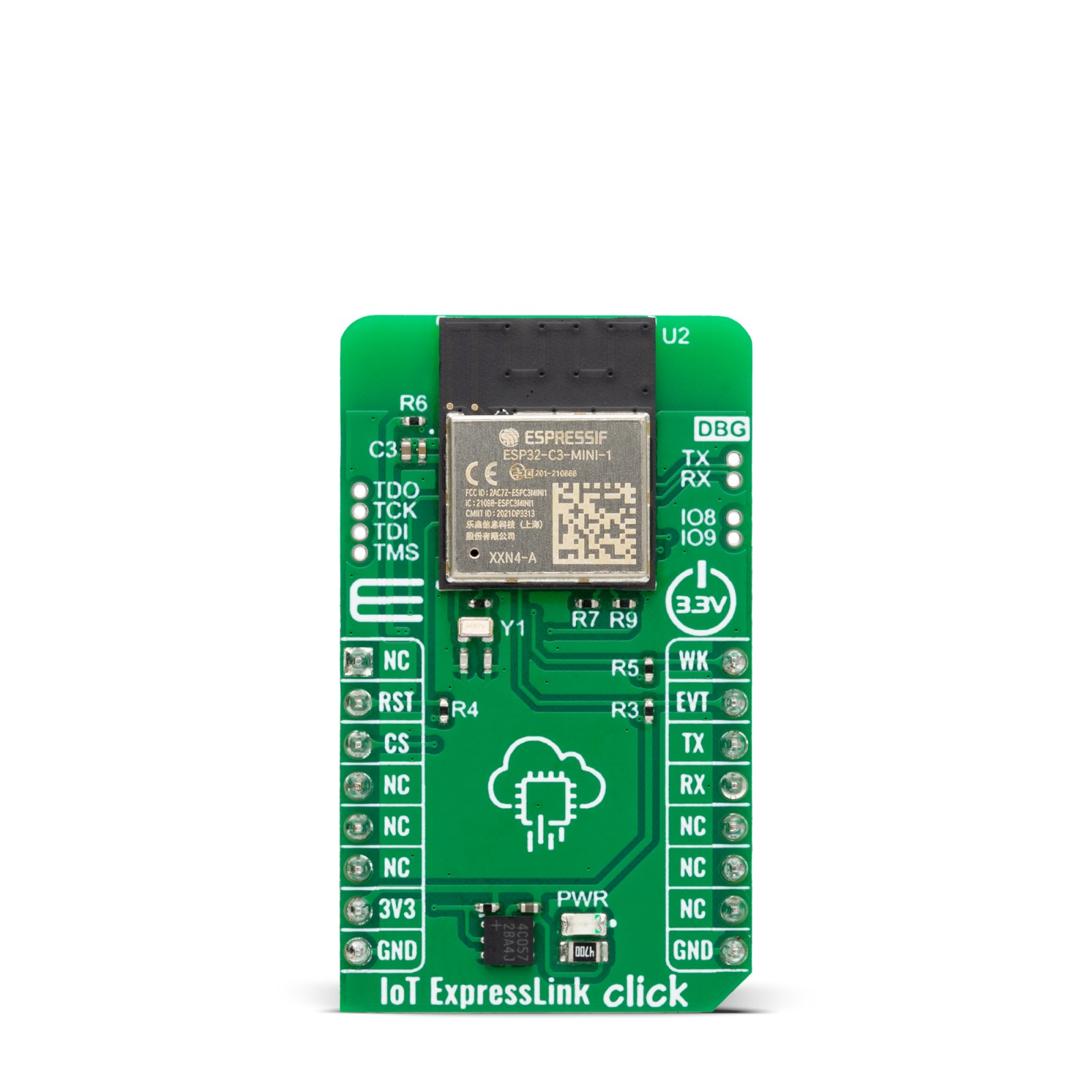
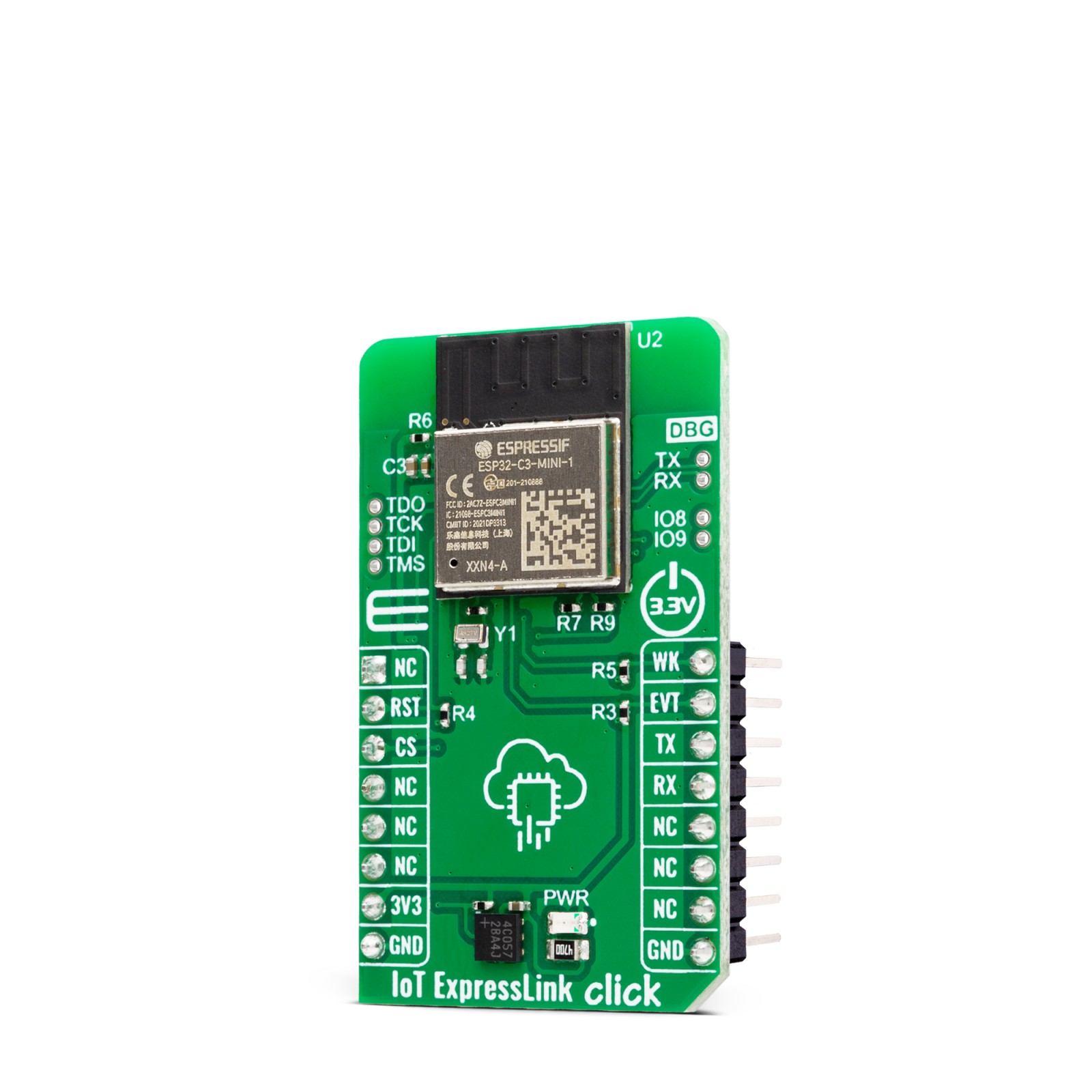
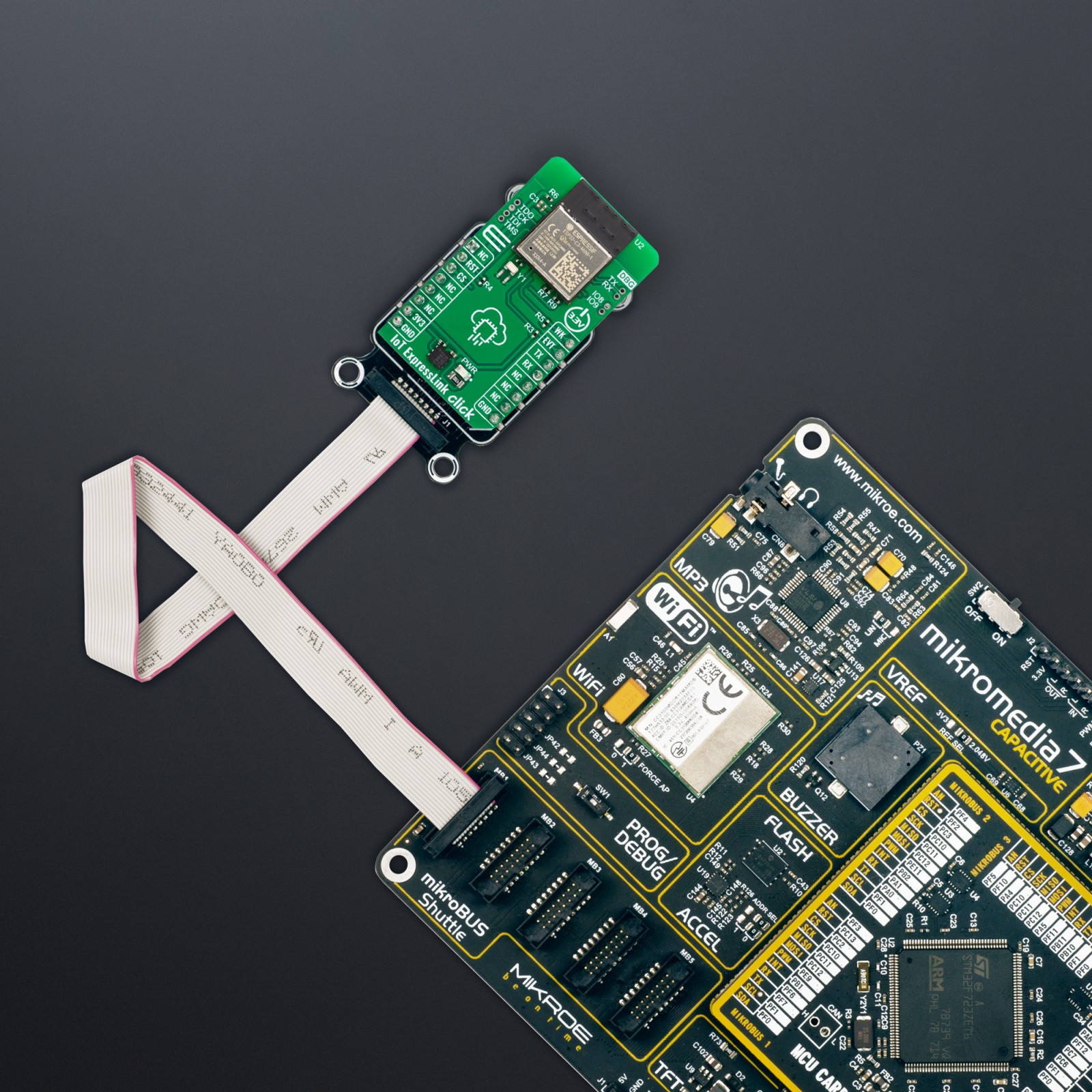
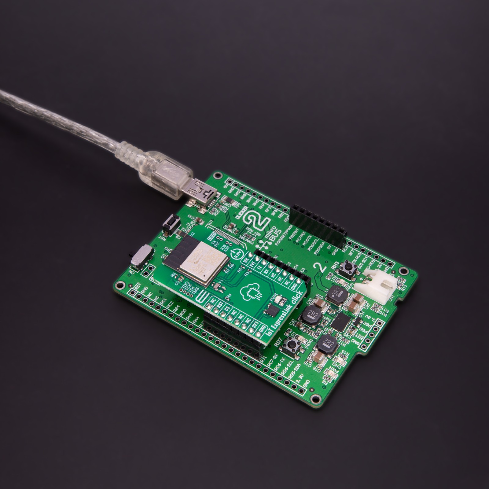
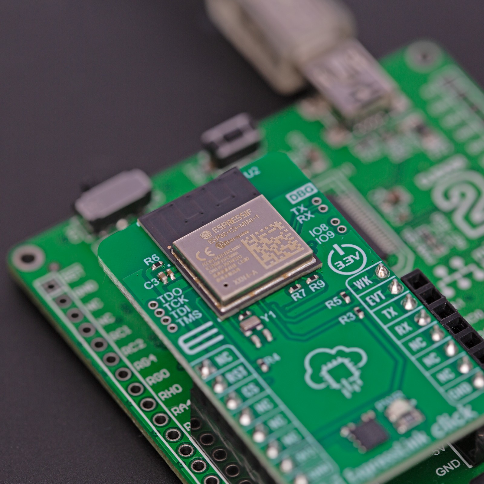
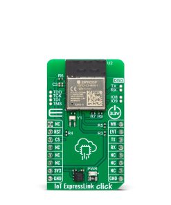
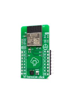
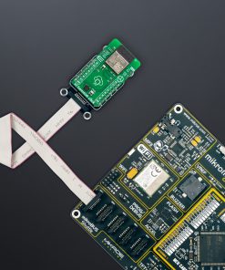
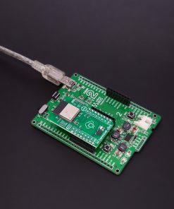
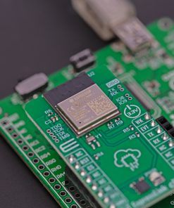
IoT ExpressLink Click is based on the ESP32-C3-MINI-1-N4-A, a 2.4GHz WiFi (802.11 b/g/n) and Bluetooth® 5 LE combo module from Espressif Systems that comes with an onboard PCB antenna and AWS IoT ExpressLink firmware (locked to the AWS). This module’s core is the ESP32C3 series of SoC RISCV single-core 32-bit microprocessor (ESP32-C3FN4), a chip with an embedded flash of 4MB and a clock speed of up to 160MHz. Since flash is packaged in the ESP32-C3FN4 chip rather than integrated into the module, the ESP32-C3-MINI-1-N4-A has a smaller package size. Thanks to its rich set of features necessary to implement IoT ExpressLink services, this Click board™ is ideal for smart homes, industrial automation, health care, consumer electronics, and generic IoT sensor hubs and data logger applications.
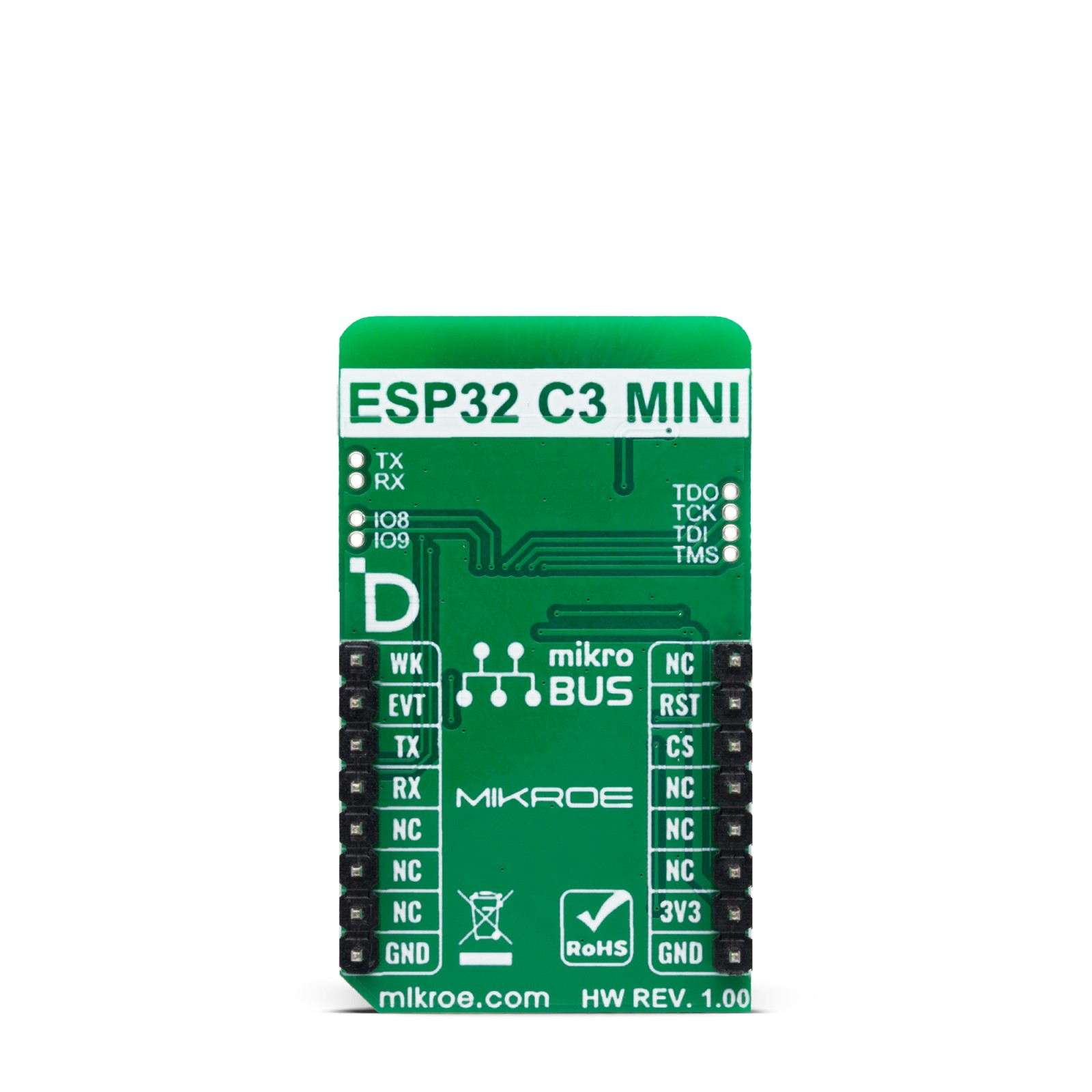
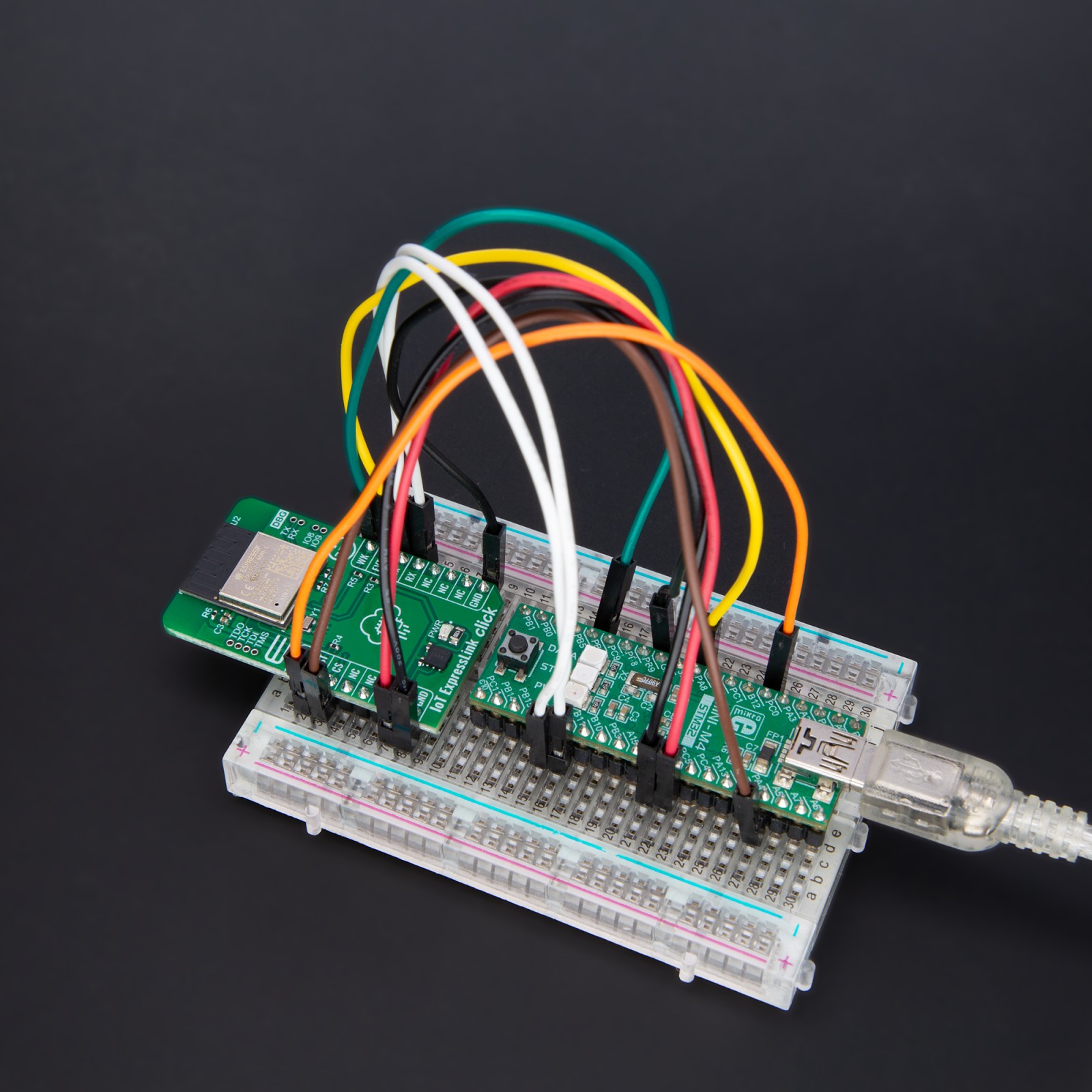
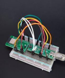
The IoT ExpressLink Click interfaces with a host MCU through UART communication, which involves sending AT commands using RX and TX pins operating at a rate of 115200bps. Besides the UART pins, this Click board™ also employs other pins of the mikroBUS™ socket to enhance its functionality. For example, the WK pin is utilized as a module wake-up pin, the EVT pin detects significant events during operation, and the device enable pin RST offers a switch operation to turn ON/OFF the module.
On the left side of the board, it is possible to find an additional unpopulated header that offers full support for debugging capabilities. With this header, the user can use a JTAG interface for debugging, available through the JTAG interface pins (TDO, TCK, TDI, and TMS). On the right side of the board, there is also a set of unpopulated headers like extra UART pins for debugging and a header with user-configurable general-purpose I/O pins.
This Click board™ can be operated only with a 3.3V logic voltage level. The board must perform appropriate logic voltage level conversion before using MCUs with different logic levels. Also, it comes equipped with a library containing functions and an example code that can be used, as a reference, for further development.
Specifications
Type
Cloud Routers,WiFi
Applications
Can be used for smart homes, industrial automation, health care, consumer electronics, and generic IoT sensor hubs and data logger applications
On-board modules
ESP32-C3-MINI-1-N4-A – WiFi and Bluetooth® 5 LE combo module from Espressif Systems
Key Features
Easily connected to IoT ExpressLink services, 2.4GHz WiFi and Bluetooth® 5 combo, 4MB flash in a single chip package, UART-based control or via demo application, additional functionality like module wake-up, JTAG interface, UART pins for debugging, GPIOs, and more
Interface
UART
Feature
ClickID
Compatibility
mikroBUS™
Click board size
M (42.9 x 25.4 mm)
Input Voltage
3.3V
Pinout diagram
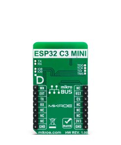
This table shows how the pinout on IoT ExpressLink Click corresponds to the pinout on the mikroBUS™ socket (the latter shown in the two middle columns).
Onboard settings and indicators
Label | Name | Default | Description |
---|---|---|---|
LD1 | PWR | – | Power LED Indicator |
J1 | – | Unpopulated | JTAG Interface for Debugging Header |
J2 | – | Unpopulated | UART Pins for Debugging Header |
J3 | – | Unpopulated | General-Purpose I/O Pins Header |
IoT ExpressLink Click electrical specifications
Description | Min | Typ | Max | Unit |
---|---|---|---|---|
Supply Voltage | – | 3.3 | – | V |
Frequency Range | – | 2.4 | – | GHz |
Data Rate | – | – | 150 | Mbps |
Software Support
We provide a library for the IoT ExpressLink Click as well as a demo application (example), developed using MIKROE compilers. The demo can run on all the main MIKROE development boards.
Package can be downloaded/installed directly from NECTO Studio Package Manager (recommended), downloaded from our LibStock™ or found on Mikroe github account.
Library Description
This library contains API for IoT ExpressLink Click driver.
Key functions
-
iotexpresslink_reset_device
This function resets device by toggling the RST pin state. -
iotexpresslink_send_cmd
This function send command string by using UART serial interface.
Example Description
This example demonstrates the use of IoT ExpressLink click board by bridging the USB UART to mikroBUS UART which allows the click board to establish a connection with the IoT ExpressLink over the Quick Connect demo application without an AWS account.
void application_task ( void )
{
app_buf_len = uart_read( &logger.uart, app_buf, PROCESS_BUFFER_SIZE );
if ( app_buf_len > 0 )
{
uart_write ( &iotexpresslink.uart, app_buf, app_buf_len );
iotexpresslink_clear_app_buf( );
}
app_buf_len = uart_read( &iotexpresslink.uart, app_buf, PROCESS_BUFFER_SIZE );
if ( app_buf_len > 0 )
{
uart_write ( &logger.uart, app_buf, app_buf_len );
iotexpresslink_clear_app_buf( );
}
}
The full application code, and ready to use projects can be installed directly from NECTO Studio Package Manager (recommended), downloaded from our LibStock™ or found on Mikroe github account.
Other Mikroe Libraries used in the example:
- MikroSDK.Board
- MikroSDK.Log
- Click.IoTExpressLink
Additional notes and informations
Depending on the development board you are using, you may need USB UART click, USB UART 2 Click or RS232 Click to connect to your PC, for development systems with no UART to USB interface available on the board. UART terminal is available in all MIKROE compilers.
mikroSDK
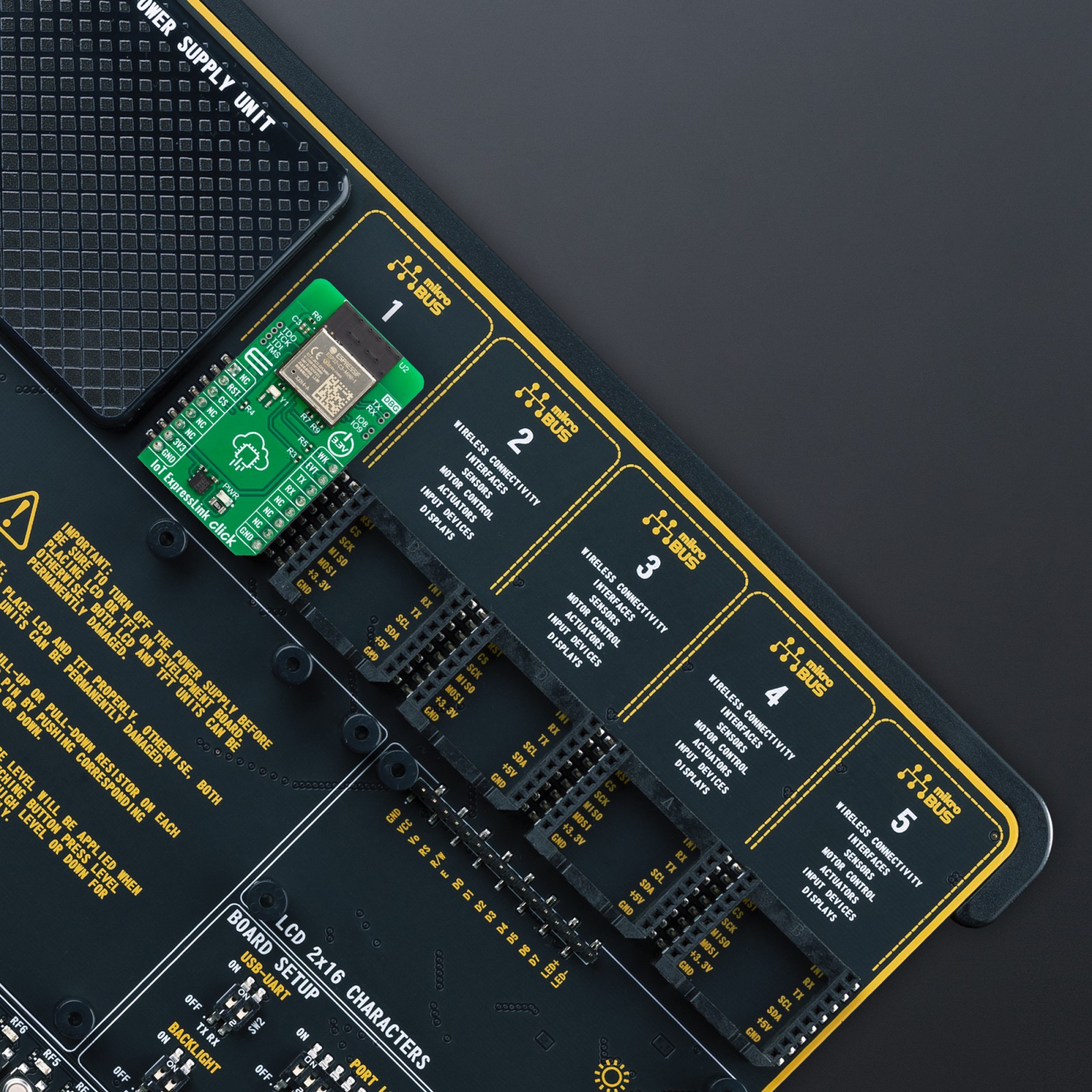
This Click board™ is supported with mikroSDK – MIKROE Software Development Kit. To ensure proper operation of mikroSDK compliant Click board™ demo applications, mikroSDK should be downloaded from the LibStock and installed for the compiler you are using.
For more information about mikroSDK, visit the official page.