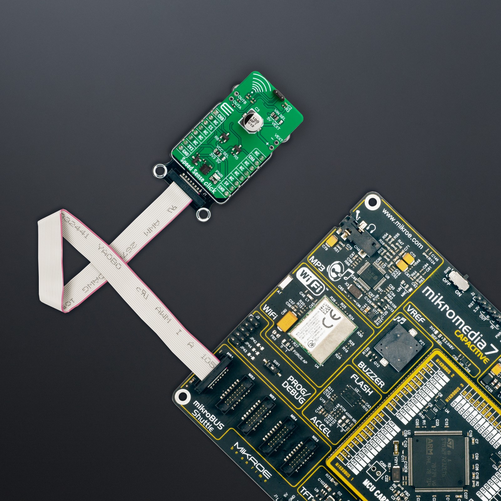
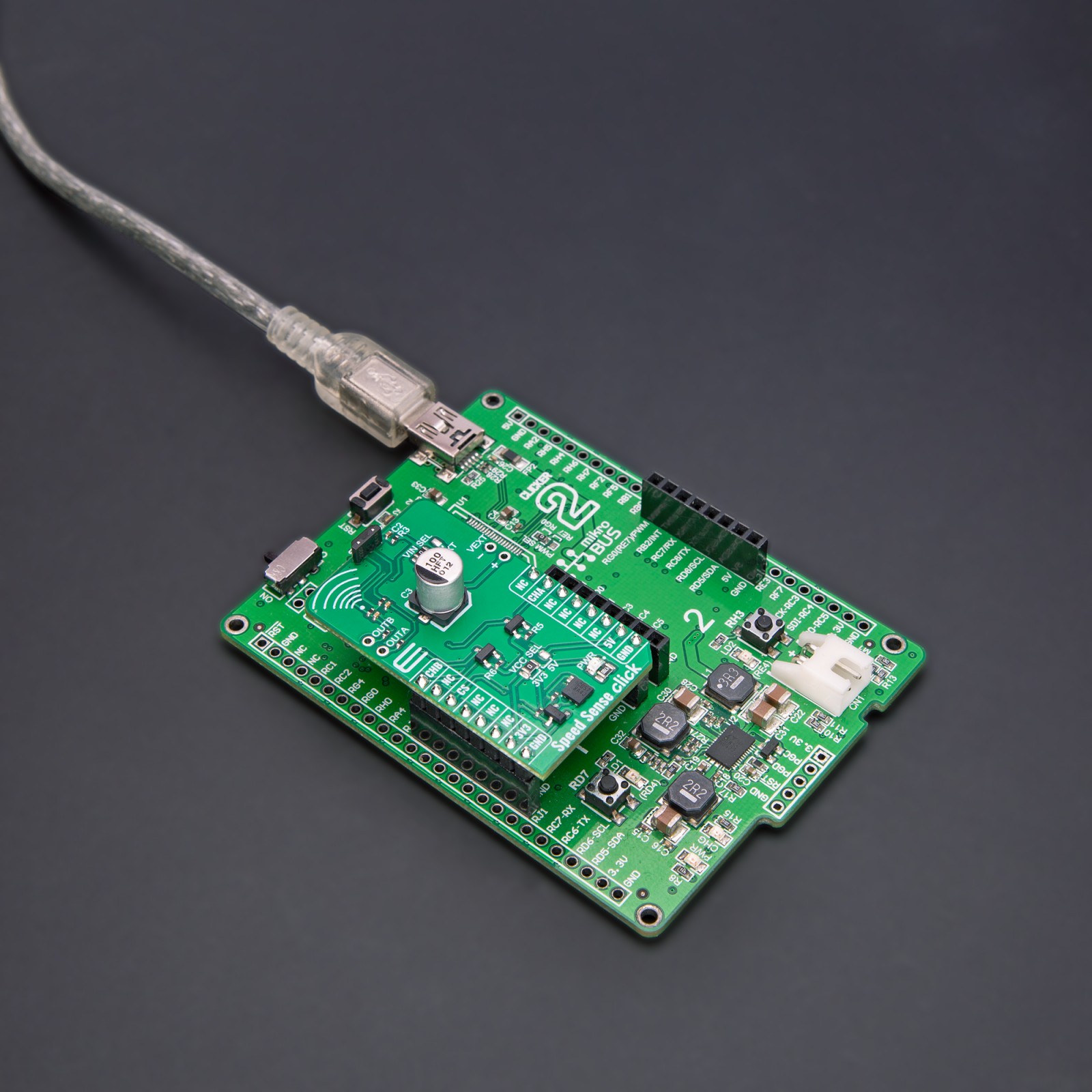
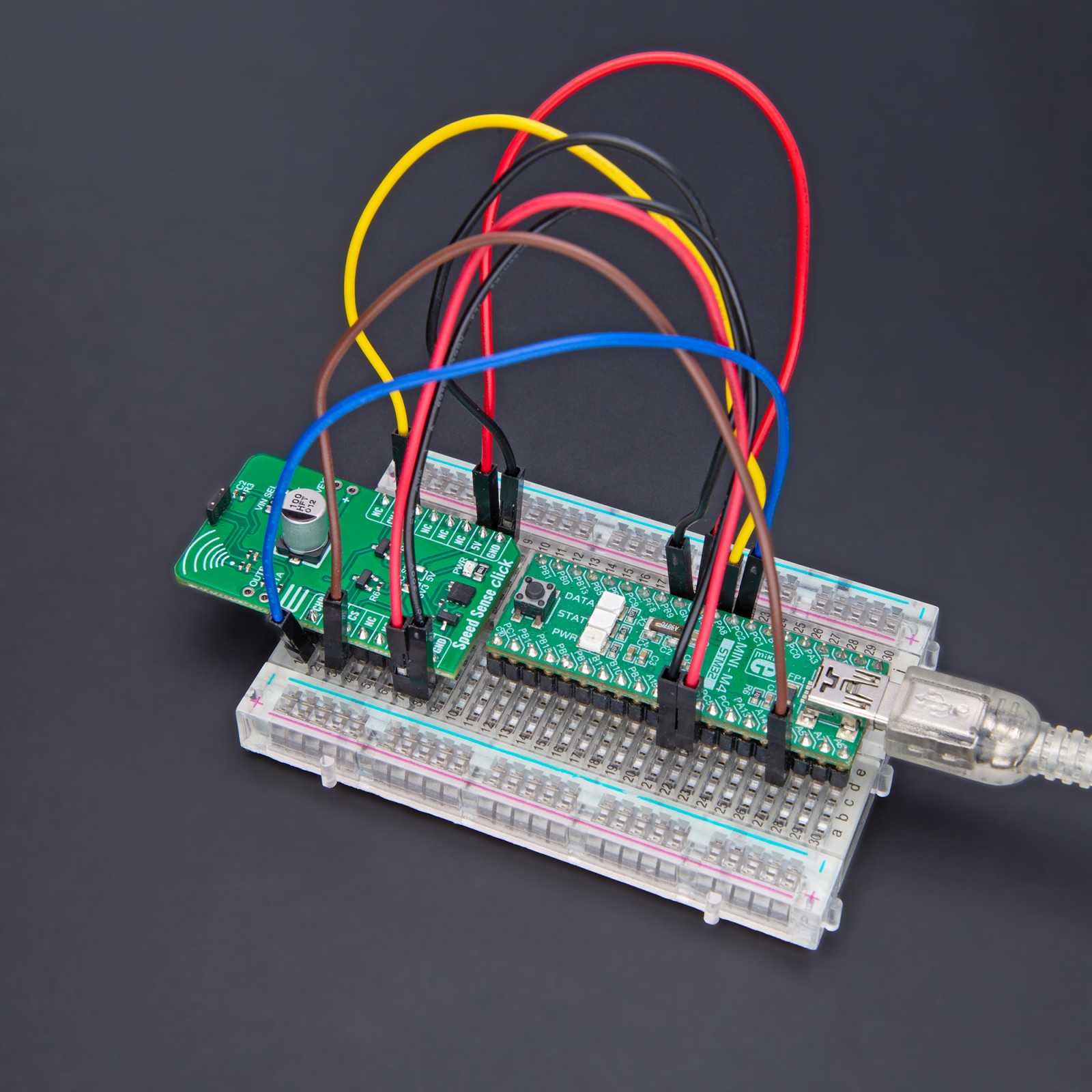
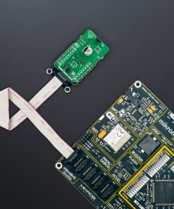
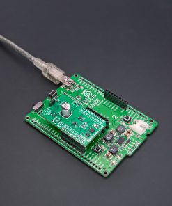
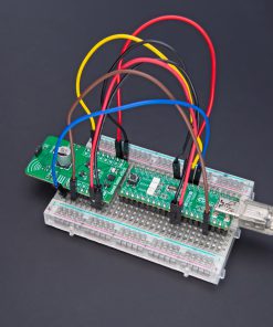
How does it work?
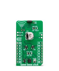
Speed Sense Click is based on the A17501, a dual output differential speed and direction sensor from Allegro Microsystems. The sensor consists of three Hall elements incorporated in such a way as to create two independent differential channels. The differential signals are used to produce a highly accurate speed output and, if desired, provide information on the direction of rotation. The advanced self-calibration technique with the digital tracking of the signal results in accurate switch points over the air gap, speed, and temperature. The sensor is immune to common external magnetic disturbance and is ideally suited for asynchronous electric motor applications.
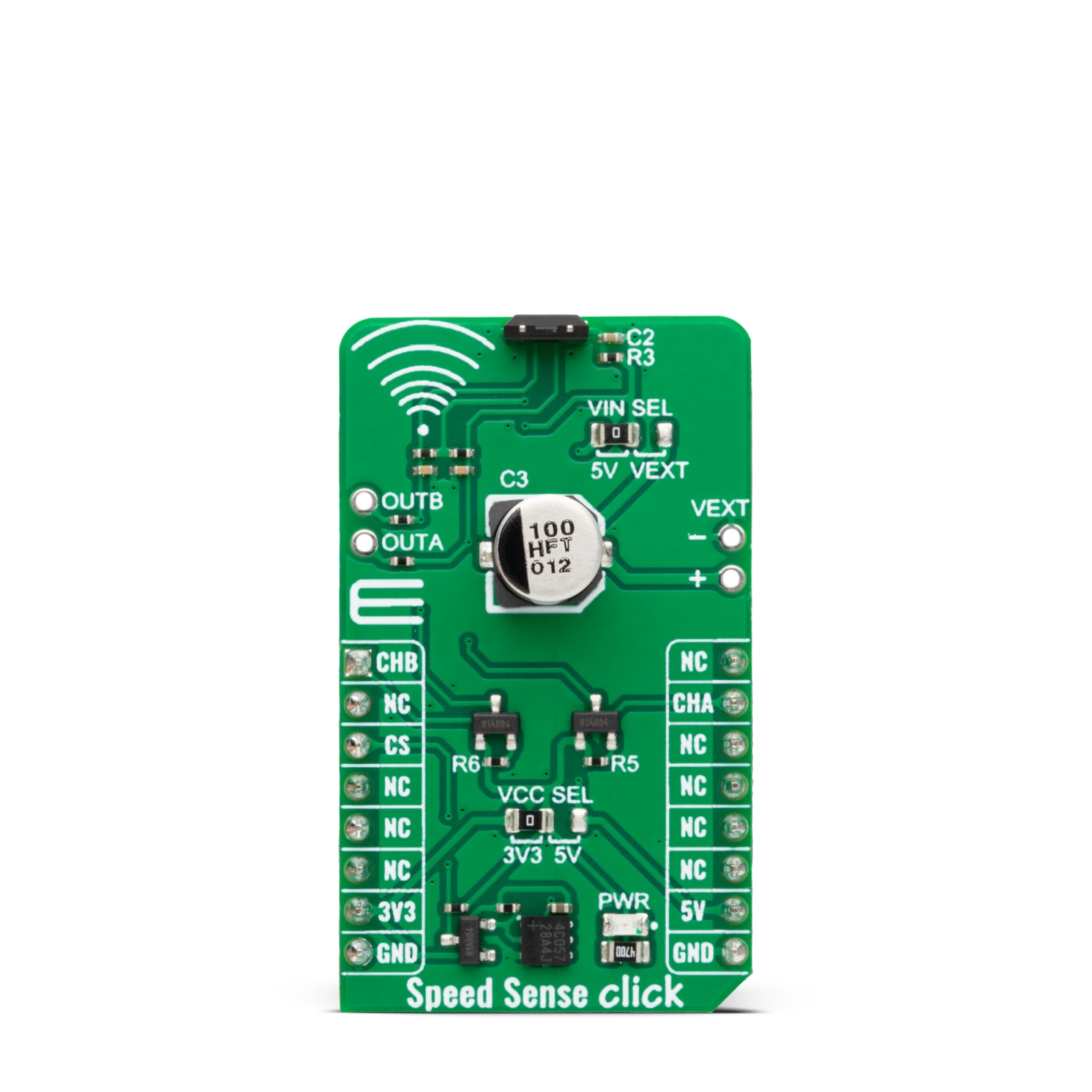
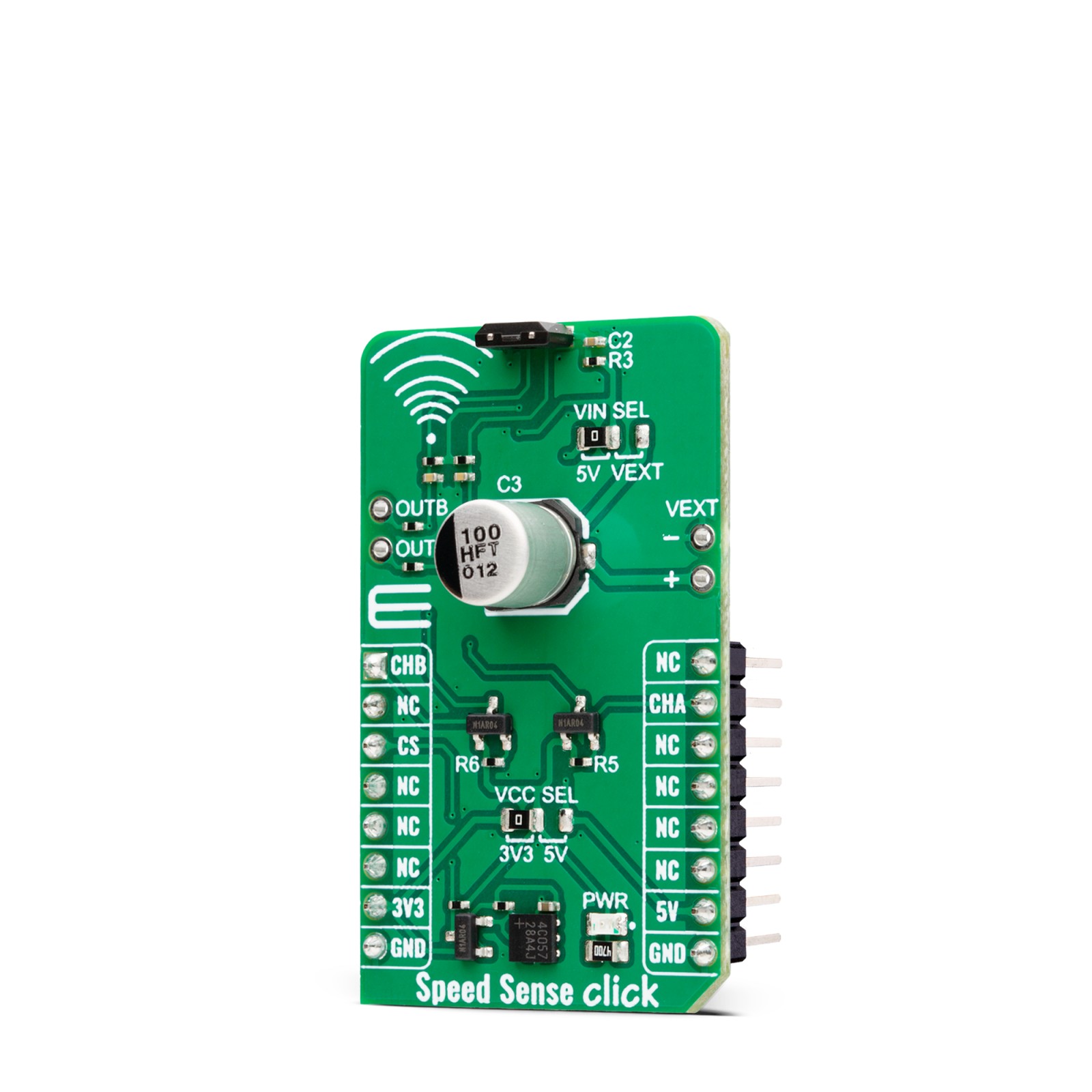
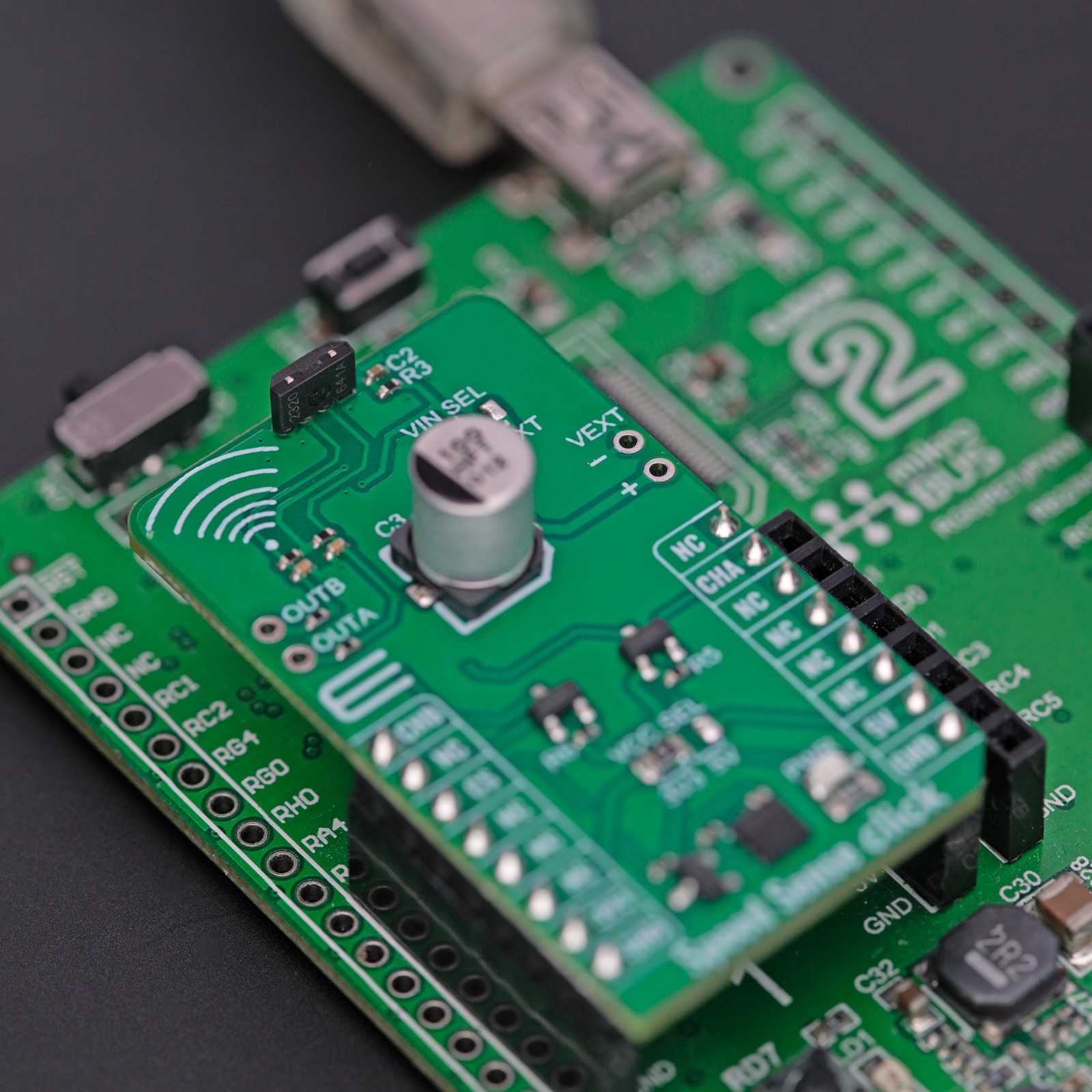
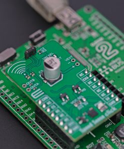
When properly back-biased, the sensor is intended for use with ring magnets or ferromagnetic targets. It poses a temperature-compensated amplifier, as well as a full-range ADC. Besides operating on 5V from the mikroBUS™ socket power rail, you can also add an external power supply over the VEXT connector from 4 up to 24V. The selection can be made over the VIN SEL.
Speed Sense Click uses general-purpose IOs to interrupt the host MCU when detecting the magnet on a spinning wheel. The output channel pins are labeled CHA and CHB. There is also an external header with these channels for connecting an external device (relay, LED, and more).
This Click board™ can operate with either 3.3V or 5V logic voltage levels selected via the VCC SEL jumper. This way, both 3.3V and 5V capable MCUs can use the communication lines properly. Also, this Click board™ comes equipped with a library containing easy-to-use functions and an example code that can be used as a reference for further development.
Specifications
Type
Motion
Applications
Can be used for the development of rotational position-sensing devices based on a ring magnet target design which is common in automotive and industrial electric motor applications
On-board modules
A17501 – dual output differential speed and direction sensor from Allegro Microsystems
Key Features
A high-speed switching bandwidth, two independent output channels, immune to common external magnetic disturbance, ideally suited for asynchronous electric motor applications, integrated EEPROM enables factory traceability throughout the product life cycle and more
Interface
GPIO
Feature
ClickID
Compatibility
mikroBUS™
Click board size
M (42.9 x 25.4 mm)
Input Voltage
3.3V or 5V,External
Pinout diagram
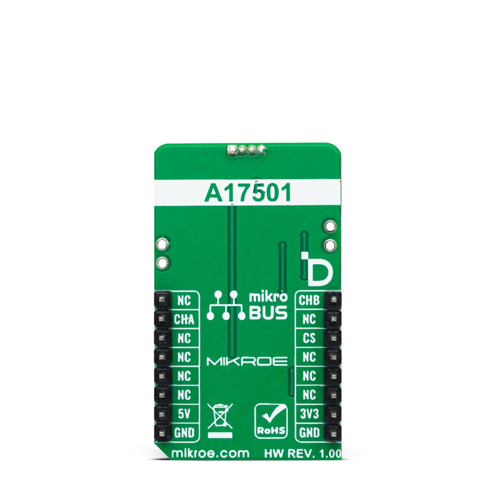
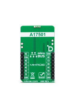
This table shows how the pinout on Speed Sense Click corresponds to the pinout on the mikroBUS™ socket (the latter shown in the two middle columns).
Onboard settings and indicators
Label | Name | Default | Description |
---|---|---|---|
LD1 | PWR | – | Power LED Indicator |
JP1 | VCC SEL | Left | Logic Level Voltage Selection 3V3/5V: Left position 3V3, Right position 5V |
JP2 | VIN SEL | Left | Power Supply Selection 5V/VEXT: Left position 5V, Right position VEXT |
Speed Sense Click electrical specifications
Description | Min | Typ | Max | Unit |
---|---|---|---|---|
Supply Voltage | 3.3 | – | 5 | V |
External Power Supply | 4 | – | 24 | V |
Operating Frequency | 0 | – | 40 | kHz |
Operating Magnetic Input Peak | -1150 | – | 1150 | G |
Software Support
We provide a library for the Speed Sense Click as well as a demo application (example), developed using MIKROE compilers. The demo can run on all the main MIKROE development boards.
Package can be downloaded/installed directly from NECTO Studio Package Manager(recommended), downloaded from our LibStock™ or found on Mikroe github account.
Library Description
This library contains API for Speed Sense Click driver.
Key functions
-
speedsense_get_speed
This function reads the state of the CHA pin used for speed output protocols. -
speedsense_get_direction
This function reads the state of the CHB pin used for direction output protocols.
Example Description
This library contains the API for the Speed Sense Click driver for the speed and direction signal state detection for every magnetic pole pair.
void application_task ( void )
{
uint8_t direction = 0, speed = 0;
speed = speedsense_get_speed( &speedsense );
direction = speedsense_get_direction( &speedsense );
if ( start_measure & speed )
{
signal_duration = time_cnt - start_timer;
start_timer = time_cnt;
if ( SPEEDSENSE_DIR_STATE_FWD == direction )
{
log_printf( &logger, " Direction: Forwardrn" );
}
else
{
log_printf( &logger, " Direction: Reversern" );
}
log_printf( &logger, " Speed: %.2f rpmrn", SPEEDSENSE_CALC_RMP / signal_duration );
log_printf( &logger, " Duration: %lu msrn", signal_duration );
log_printf( &logger, " Time: %lu msrn", time_cnt );
log_printf( &logger, "-----------------------rn" );
start_measure = SPEEDSENSE_STOP_MEASURE;
}
else if ( ( !start_measure ) & ( !speed ) )
{
start_measure = SPEEDSENSE_START_NEW_MEASURE;
}
time_cnt++;
Delay_ms( 1 );
}
The full application code, and ready to use projects can be installed directly from NECTO Studio Package Manager(recommended), downloaded from our LibStock™ or found on Mikroe github account.
Other Mikroe Libraries used in the example:
- MikroSDK.Board
- MikroSDK.Log
- Click.SpeedSense
Additional notes and informations
Depending on the development board you are using, you may need USB UART click, USB UART 2 Click or RS232 Click to connect to your PC, for development systems with no UART to USB interface available on the board. UART terminal is available in all MIKROE compilers.
mikroSDK
This Click board™ is supported with mikroSDK – MIKROE Software Development Kit. To ensure proper operation of mikroSDK compliant Click board™ demo applications, mikroSDK should be downloaded from the LibStock and installed for the compiler you are using.
For more information about mikroSDK, visit the official page.