How does it work?
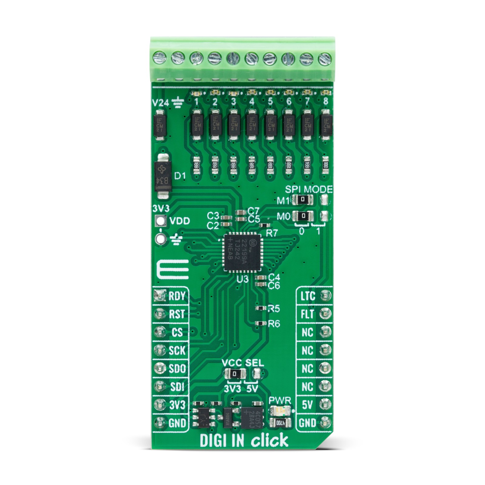
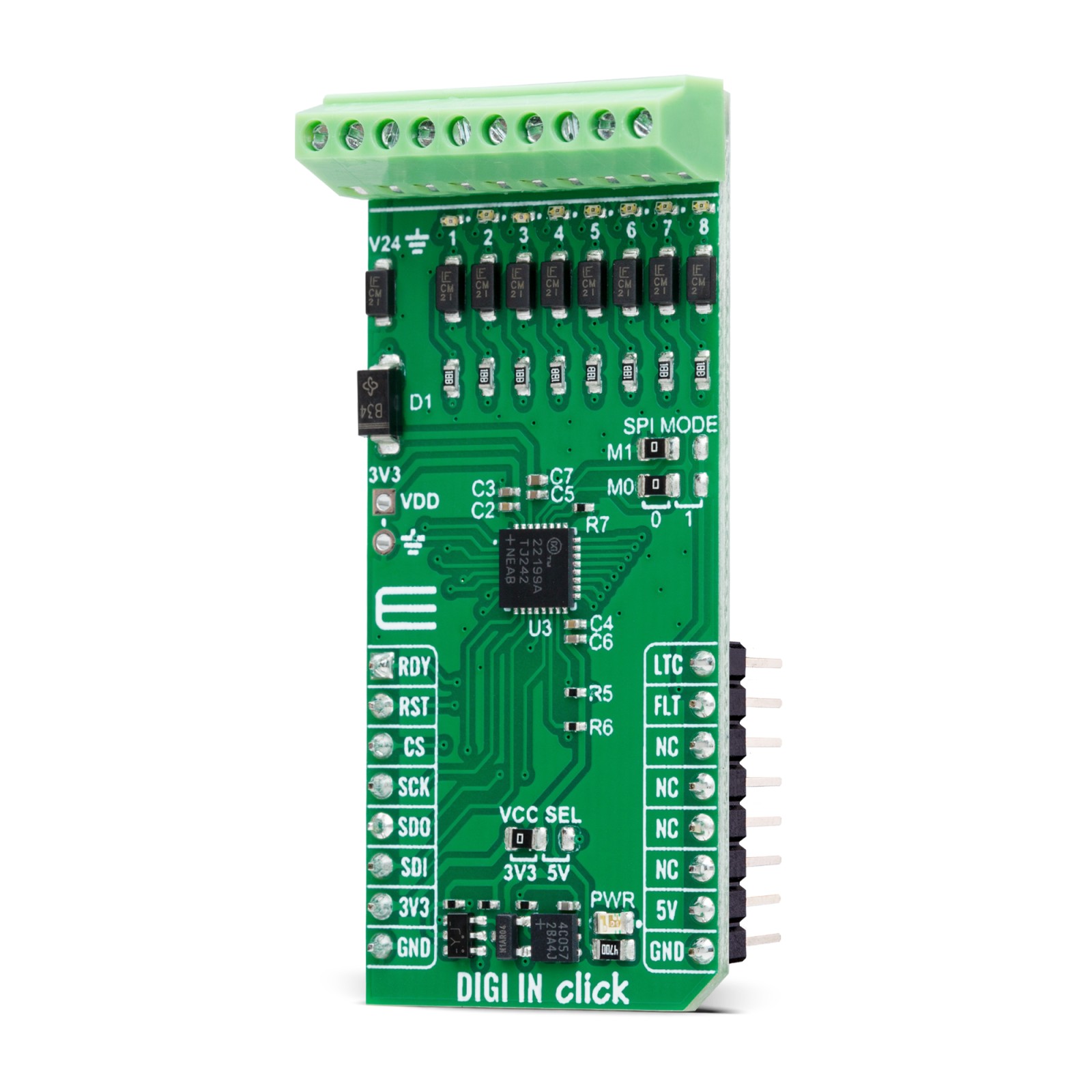
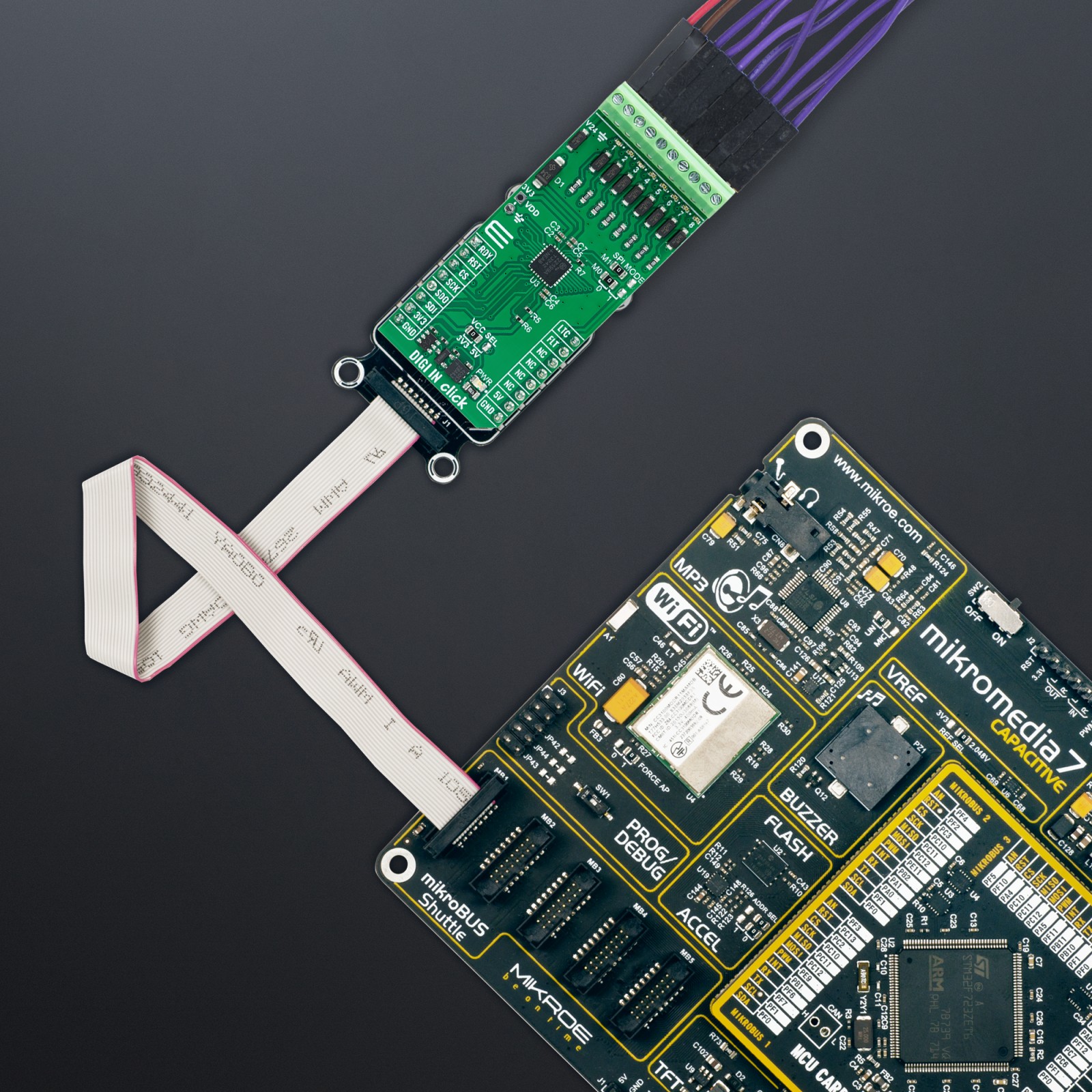
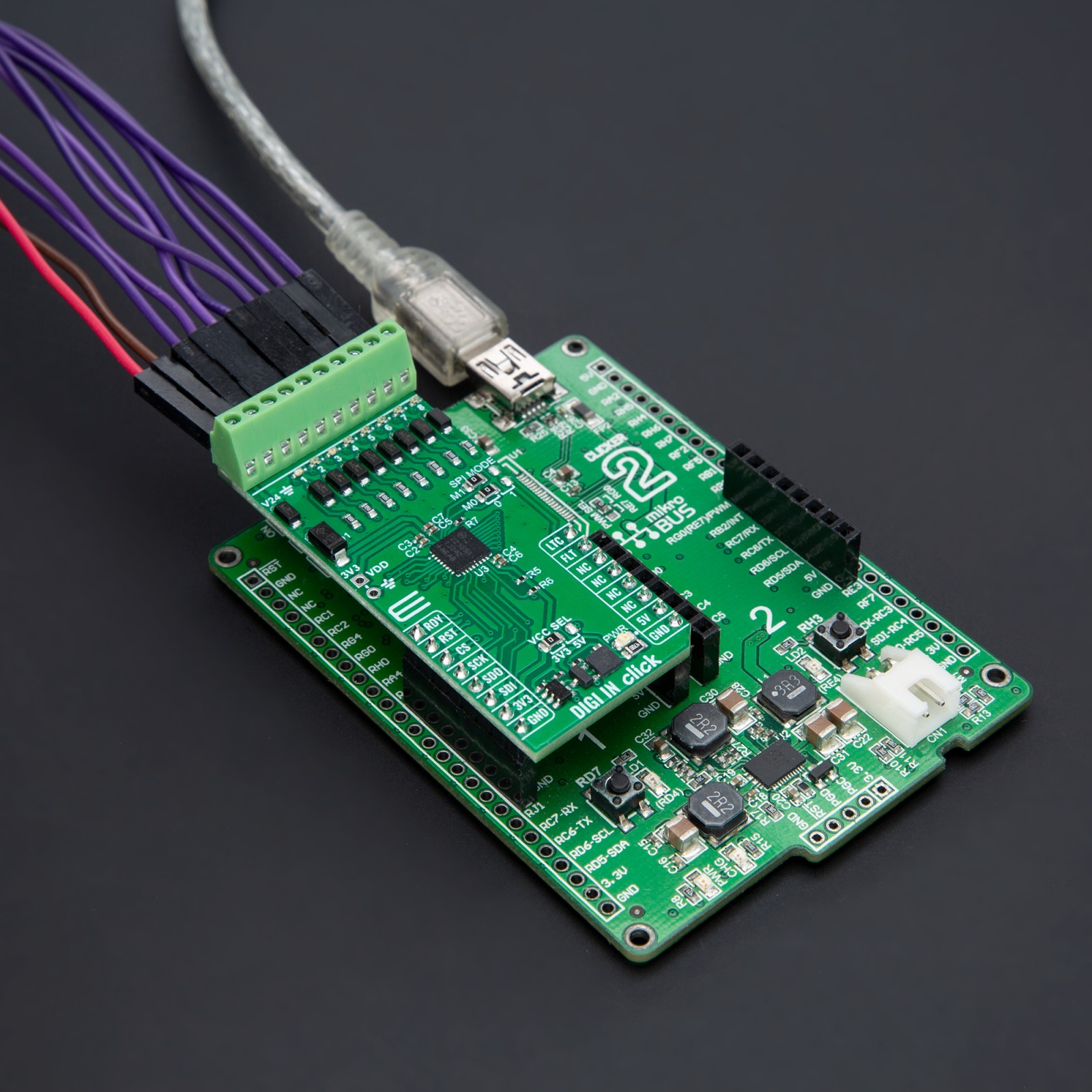
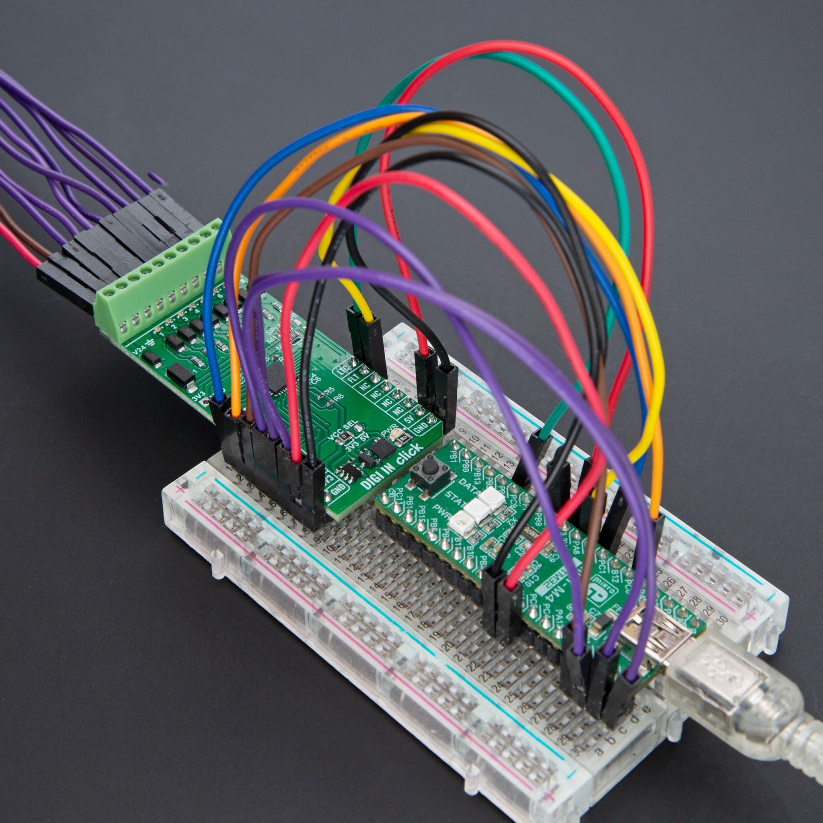
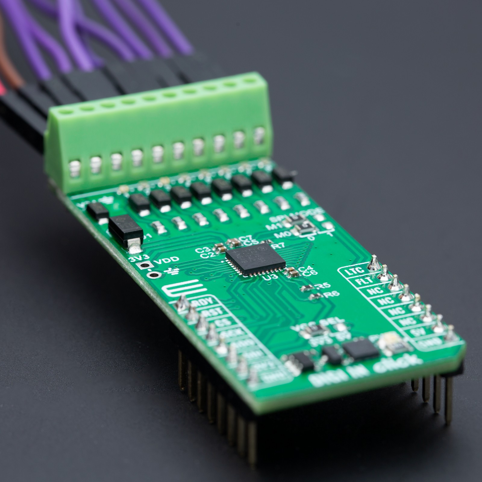
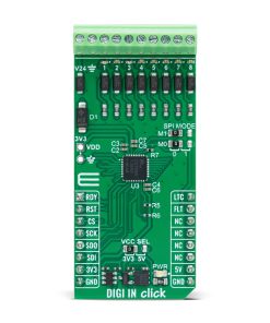
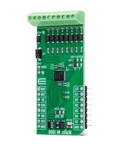
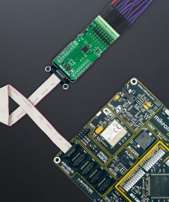
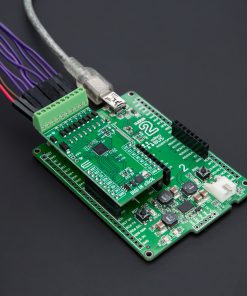
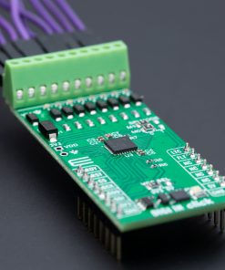
DIGI IN Click is based on the MAX22199, an octal industrial digital input module from Analog Devices. The MAX22199 complies with the IEC 61131-2 standard for industrial digital input devices. It efficiently converts eight 7-24V current-sinking industrial inputs into a serialized output compatible with SPI, supporting both 3V and 5V logic systems. It can function as eight Type 1 / Type 3 digital inputs or four Type 2 digital inputs. The eight yellow LEDs numbered 1 through 8, provide immediate visual feedback on the status of the digital input channels, whether active or not. This Click board™ is designed for various applications, including programmable logic controllers, distributed control systems, motor control applications, and building automation systems.
To ensure reliability in the demanding conditions of industrial environments, the MAX22199 incorporates a customizable glitch filter for each input, with noise filters that can be independently set to any of eight durations ranging from 50µs to 20ms or completely bypassed. The device’s connectivity is facilitated through a 4-pin SPI interface and an LTC latch input, allowing synchronized data sampling across multiple devices. In addition, the MAX22199 is equipped with several diagnostic features, including protection against thermal overload, alarms for under voltage and missing voltage conditions on the 24V supply, and detection mechanisms for SPI and CRC communication errors. These errors can trigger an interrupt signal via the FLT pin. Besides these pins, the mikroBUS™ socket also includes a READY (RDY) pin, which signals when the MAX22199 is operational by transitioning to a LOW state.
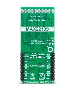
An additional feature of the board is the provision of SPI MODE jumpers, which offer control over the SPI Mode settings from 0 to 3. Adjusting the M1 jumper to position 1 activates the SPI daisy-chain mode, whereas setting the M0 jumper to position 1 turns off the CRC error detection feature. The device is powered by a single 7V to 24V supply connected to the V24 terminal. It also includes an integrated LDO regulator that not only powers the MAX22199 but also provides a 3.3V output capable of delivering up to 25mA to external circuits. It should be noted that if this pin is used as a supply of the MAX22199, no power supply should be connected to the V24 terminal.
This Click board™ can operate with either 3.3V or 5V logic voltage levels selected via the VCC SEL jumper. This way, both 3.3V and 5V capable MCUs can use the communication lines properly. Also, this Click board™ comes equipped with a library containing easy-to-use functions and an example code that can be used as a reference for further development.
Specifications
Type
Port expander
Applications
Ideal for programmable logic controllers, distributed control systems, motor control, and building automation
On-board modules
MAX22199 – octal industrial digital input from Analog Devices
Key Features
IEC 61131-2 compliant, 7-24V current-sinking industrial inputs, Type 1/Type 3 digital inputs or four Type 2 digital inputs, diagnostics, programmable glitch filter, integrated LDO capable of 3.3V/25mA output, SPI mode control, and more
Interface
SPI
Feature
ClickID
Compatibility
mikroBUS™
Click board size
L (57.15 x 25.4 mm)
Input Voltage
3.3V or 5V,External
Pinout diagram
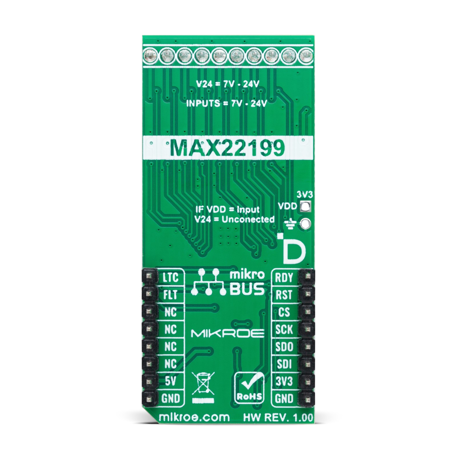
This table shows how the pinout on DIGI IN Click corresponds to the pinout on the mikroBUS™ socket (the latter shown in the two middle columns).
Onboard settings and indicators
Label | Name | Default | Description |
---|---|---|---|
LD1 | PWR | – | Power LED Indicator |
LD2-LD9 | 1-8 | – | Active Channel LED Indicators |
JP1 | VCC SEL | Left | Power Voltage Level Selection 3V3/5V: Left position 3V3, Right position 5V |
JP3-JP4 | SPI MODE | Left | SPI Mode Selection 0/1: Left position 0, Right position 1 |
DIGI IN Click electrical specifications
Description | Min | Typ | Max | Unit |
---|---|---|---|---|
Supply Voltage | 3.3 | – | 5 | V |
External Supply Voltage | 7 | – | 24 | V |
Software Support
We provide a library for the DIGI IN Click as well as a demo application (example), developed using MIKROE compilers. The demo can run on all the main MIKROE development boards.
Package can be downloaded/installed directly from NECTO Studio Package Manager(recommended), downloaded from our LibStock™ or found on Mikroe github account.
Library Description
This library contains API for DIGI IN Click driver.
Key functions
-
digiin_write_reg
This function is used to write data into the selected register by using SPI serial interface. -
digiin_read_reg
This function reads a data byte from the selected register by using SPI serial interface. -
digiin_pulse_latch
This function is used to generate LATCH pulse for capturing channel data.
Example Description
This example demonstrates the use of DIGI IN Click board™ by reading and displaying the state of the channels.
void application_task ( void )
{
uint8_t channel_data = 0;
digiin_pulse_latch( &digiin );
if ( DIGIIN_OK == digiin_read_reg( &digiin, DIGIIN_REG_DISTATE, &channel_data ) )
{
if ( channel_data & DIGIIN_CHANNEL_1_MASK )
{
log_printf( &logger, "Channel 1 State: HIGH rn" );
}
else
{
log_printf( &logger, "Channel 1 State: LOW rn" );
}
if ( channel_data & DIGIIN_CHANNEL_2_MASK )
{
log_printf( &logger, "Channel 2 State: HIGH rn" );
}
else
{
log_printf( &logger, "Channel 2 State: LOW rn" );
}
if ( channel_data & DIGIIN_CHANNEL_3_MASK )
{
log_printf( &logger, "Channel 3 State: HIGH rn" );
}
else
{
log_printf( &logger, "Channel 3 State: LOW rn" );
}
if ( channel_data & DIGIIN_CHANNEL_4_MASK )
{
log_printf( &logger, "Channel 4 State: HIGH rn" );
}
else
{
log_printf( &logger, "Channel 4 State: LOW rn" );
}
if ( channel_data & DIGIIN_CHANNEL_5_MASK )
{
log_printf( &logger, "Channel 5 State: HIGH rn" );
}
else
{
log_printf( &logger, "Channel 5 State: LOW rn" );
}
if ( channel_data & DIGIIN_CHANNEL_6_MASK )
{
log_printf( &logger, "Channel 6 State: HIGH rn" );
}
else
{
log_printf( &logger, "Channel 6 State: LOW rn" );
}
if ( channel_data & DIGIIN_CHANNEL_7_MASK )
{
log_printf( &logger, "Channel 7 State: HIGH rn" );
}
else
{
log_printf( &logger, "Channel 7 State: LOW rn" );
}
if ( channel_data & DIGIIN_CHANNEL_8_MASK )
{
log_printf( &logger, "Channel 8 State: HIGH rn" );
}
else
{
log_printf( &logger, "Channel 8 State: LOW rn" );
}
log_printf( &logger, "- - - - - - - - - - - - - -rn" );
}
else
{
log_error( &logger, " Read error." );
}
if ( DIGIIN_PIN_STATE_HIGH == digiin_get_flt_pin( &digiin ) )
{
uint8_t flt_data = 0;
digiin_read_reg( &digiin, DIGIIN_REG_FAULT1, &flt_data );
log_printf( &logger, "Fault1 data: 0x%.2X rn", ( uint16_t ) flt_data );
digiin_read_reg( &digiin, DIGIIN_REG_FAULT2, &flt_data );
log_printf( &logger, "Fault2 data: 0x%.2X rn", ( uint16_t ) flt_data );
log_printf( &logger, "- - - - - - - - - - - - - -rn" );
}
Delay_ms( 1000 );
}
The full application code, and ready to use projects can be installed directly from NECTO Studio Package Manager(recommended), downloaded from our LibStock™ or found on Mikroe github account.
Other Mikroe Libraries used in the example:
- MikroSDK.Board
- MikroSDK.Log
- Click.DIGIIN
Additional notes and informations
Depending on the development board you are using, you may need USB UART click, USB UART 2 Click or RS232 Click to connect to your PC, for development systems with no UART to USB interface available on the board. UART terminal is available in all MIKROE compilers.
mikroSDK
This Click board™ is supported with mikroSDK – MIKROE Software Development Kit. To ensure proper operation of mikroSDK compliant Click board™ demo applications, mikroSDK should be downloaded from the LibStock and installed for the compiler you are using.
For more information about mikroSDK, visit the official page.