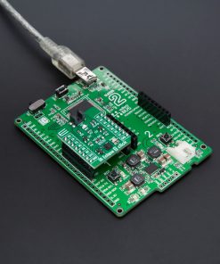
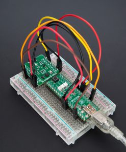
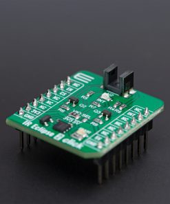
How does it work?
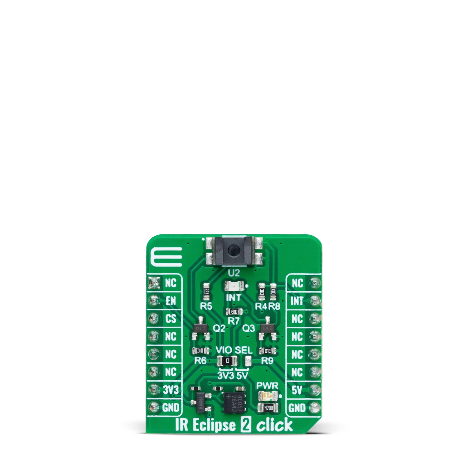
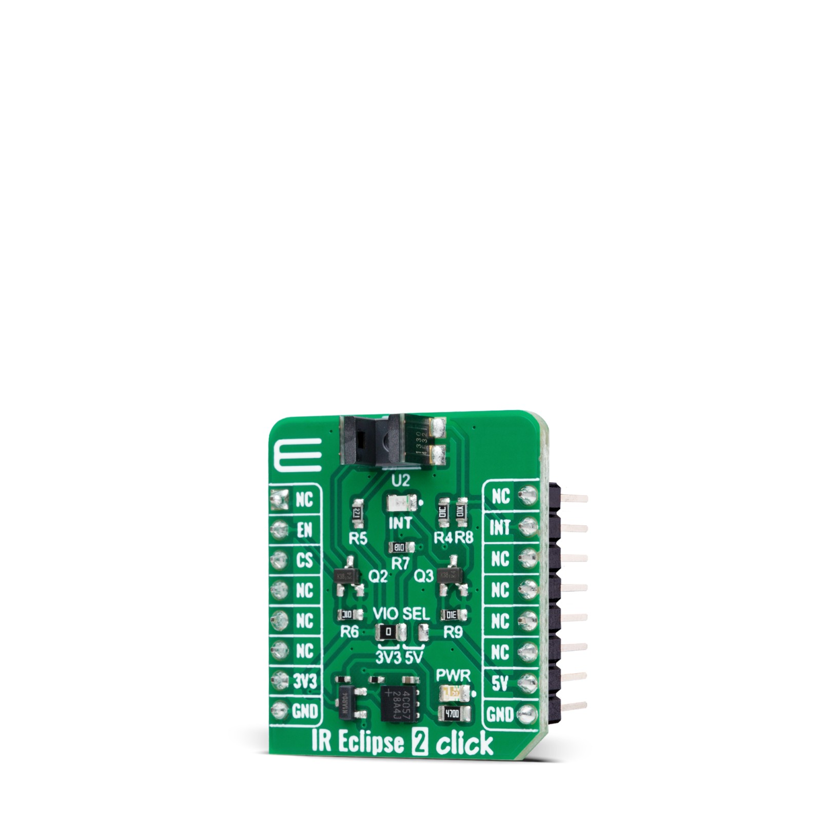
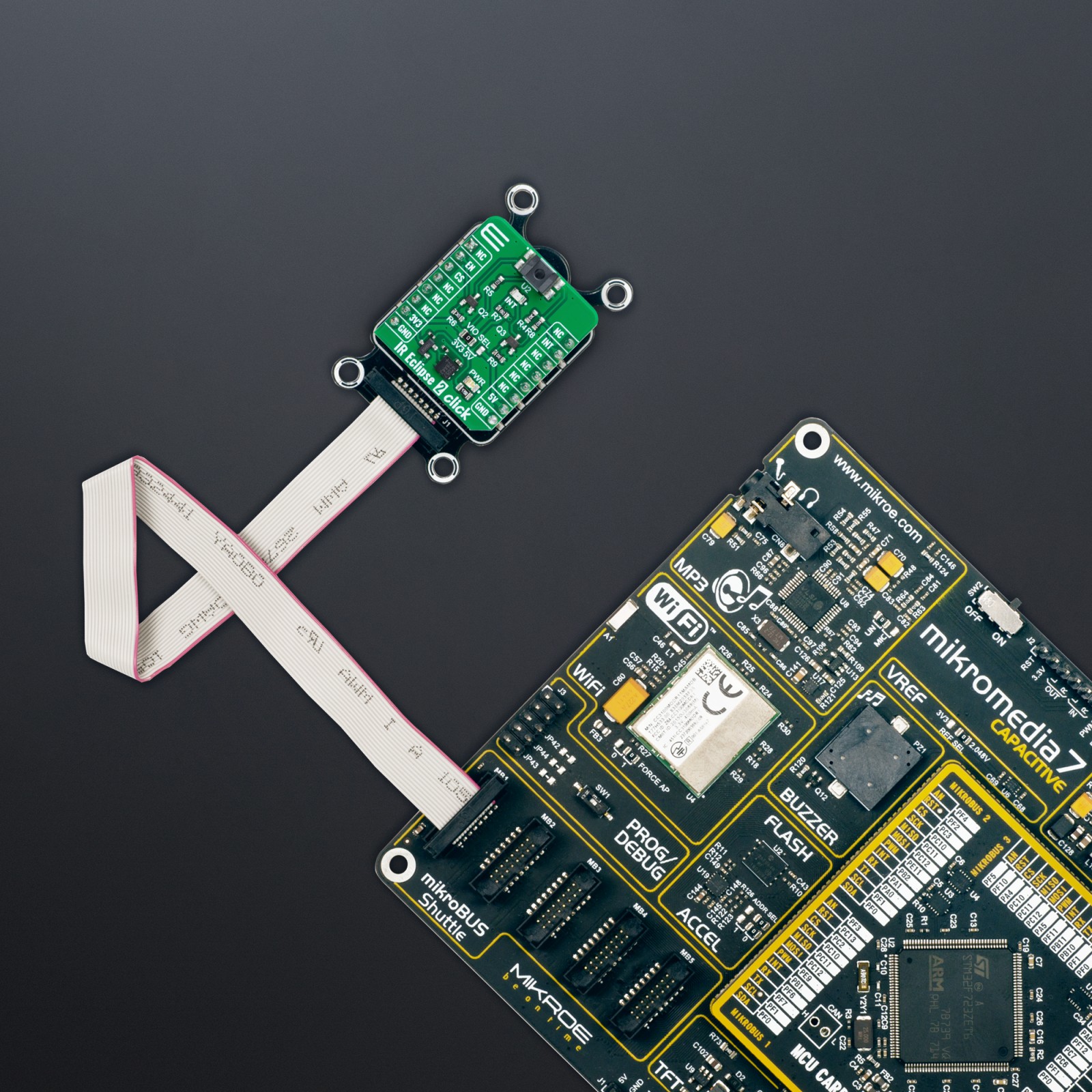
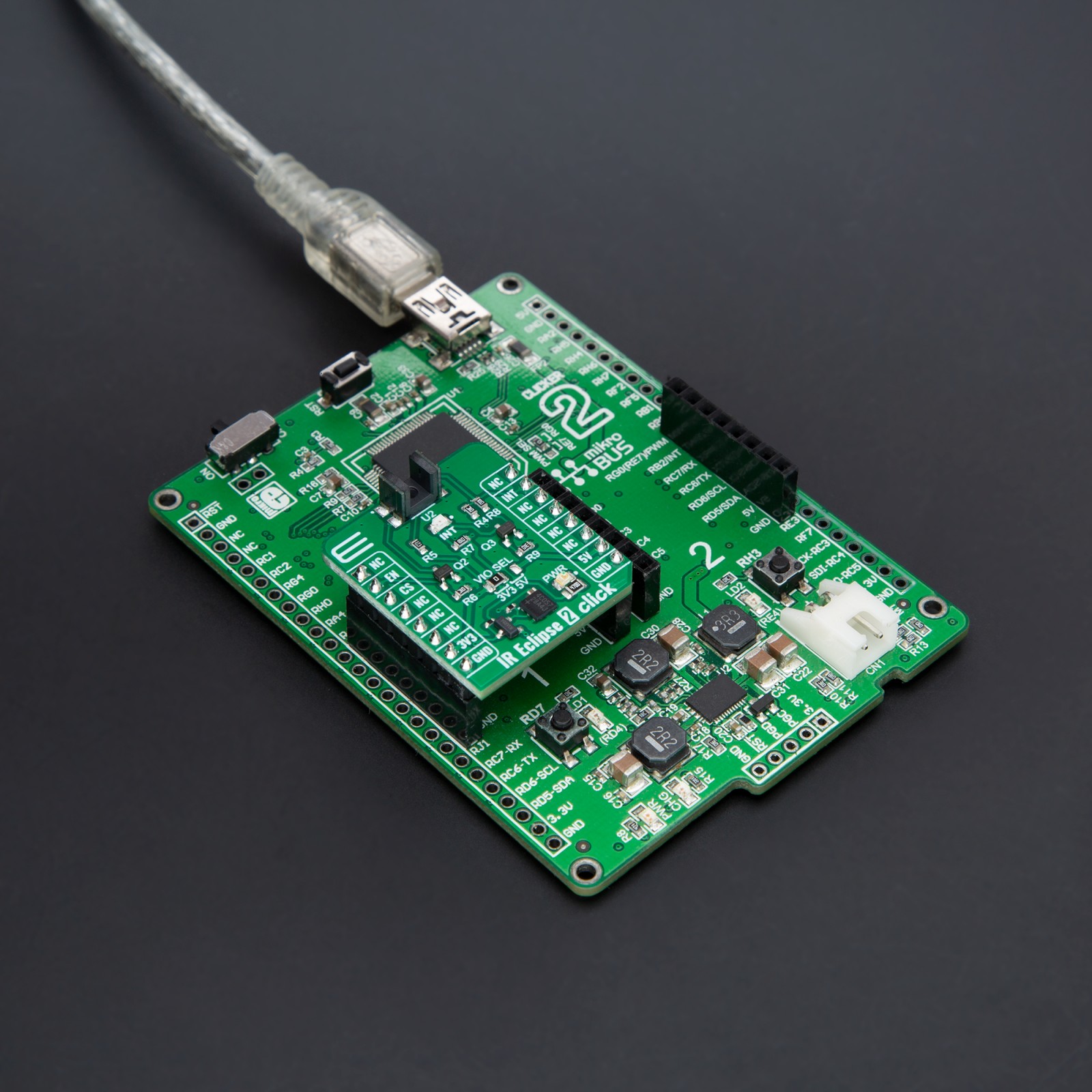
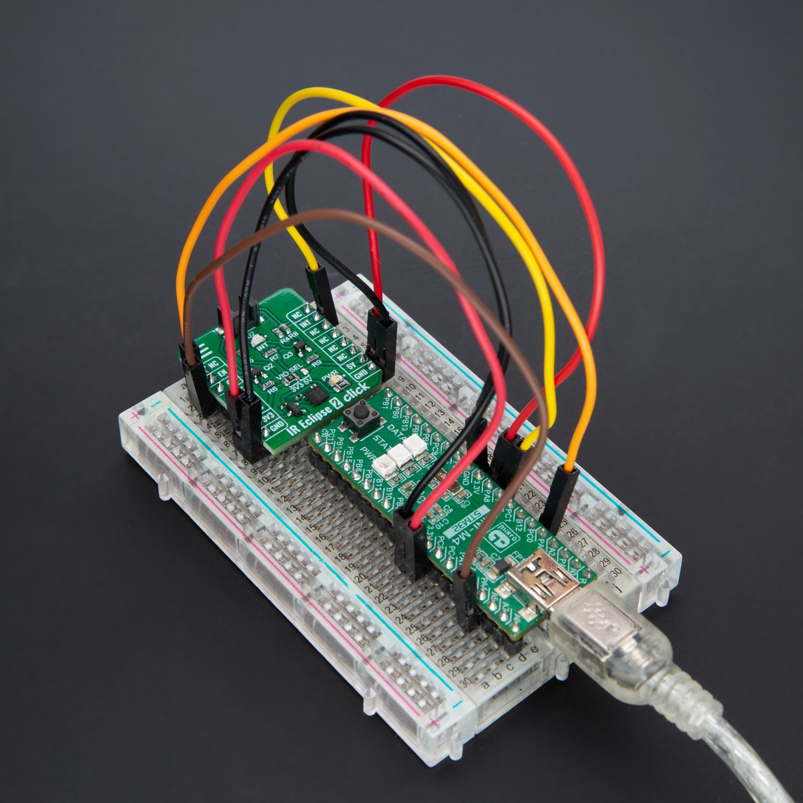
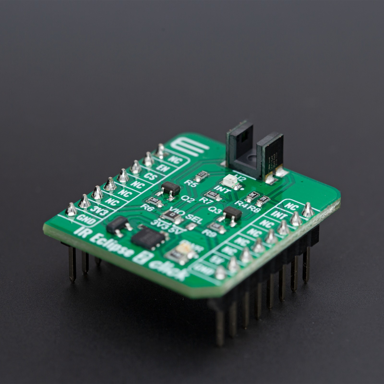
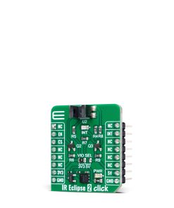
IR Eclipse 2 Click is based on the EE-SX1330, a transmissive photomicrosensor with a phototransistor output from OMRON. It consists of one infrared transmitter and receiver facing each other and spaced apart by a 3mm slit. The sensor activates when an object in the gap, like a piece of paper, eclipses the transmitter beam. The object intercepts the optical beam of the emitter, thus reducing the amount of the optical energy reaching the detector. Some smaller objects do not fully intercept the optical beam emitted by LED; therefore, some parts of the beam come to the detector and allow current flow from the phototransistor (considered noise).
The IR Eclipse 2 Click communicates with the host MCU using only the INT and EN pins of the mikroBUS™ socket. The EN pin provides a standard device enable feature, while the INT pin provides information to the MCU about the presence of an object in the gap and the sensor’s activity. Also, the INT LED serves as a visual indicator of the activated sensor (object detection indicator).
This Click board™ can operate with either 3.3V or 5V logic voltage levels selected via the VIO SEL jumper. This way, both 3.3V and 5V capable MCUs can use the communication lines properly. Also, this Click board™ comes equipped with a library containing easy-to-use functions and an example code that can be used as a reference for further development.
Specifications
Type
Optical
Applications
Can be used for printers, laser-level line tools, and other applications requiring photo interrupter ability, detecting a moving part, or even a rotation speed
On-board modules
EE-SX1330 – transmissive photomicrosensor with a phototransistor output from OMRON
Key Features
Photo interrupter ability for any application, up to 3mm detection space, detection through digital signal, device enable feature, object detection LED indicator, board compatible with both 3.3V and 5V capable MCUs, and more
Interface
GPIO
Feature
ClickID
Compatibility
mikroBUS™
Click board size
S (28.6 x 25.4 mm)
Input Voltage
3.3V or 5V
Pinout diagram
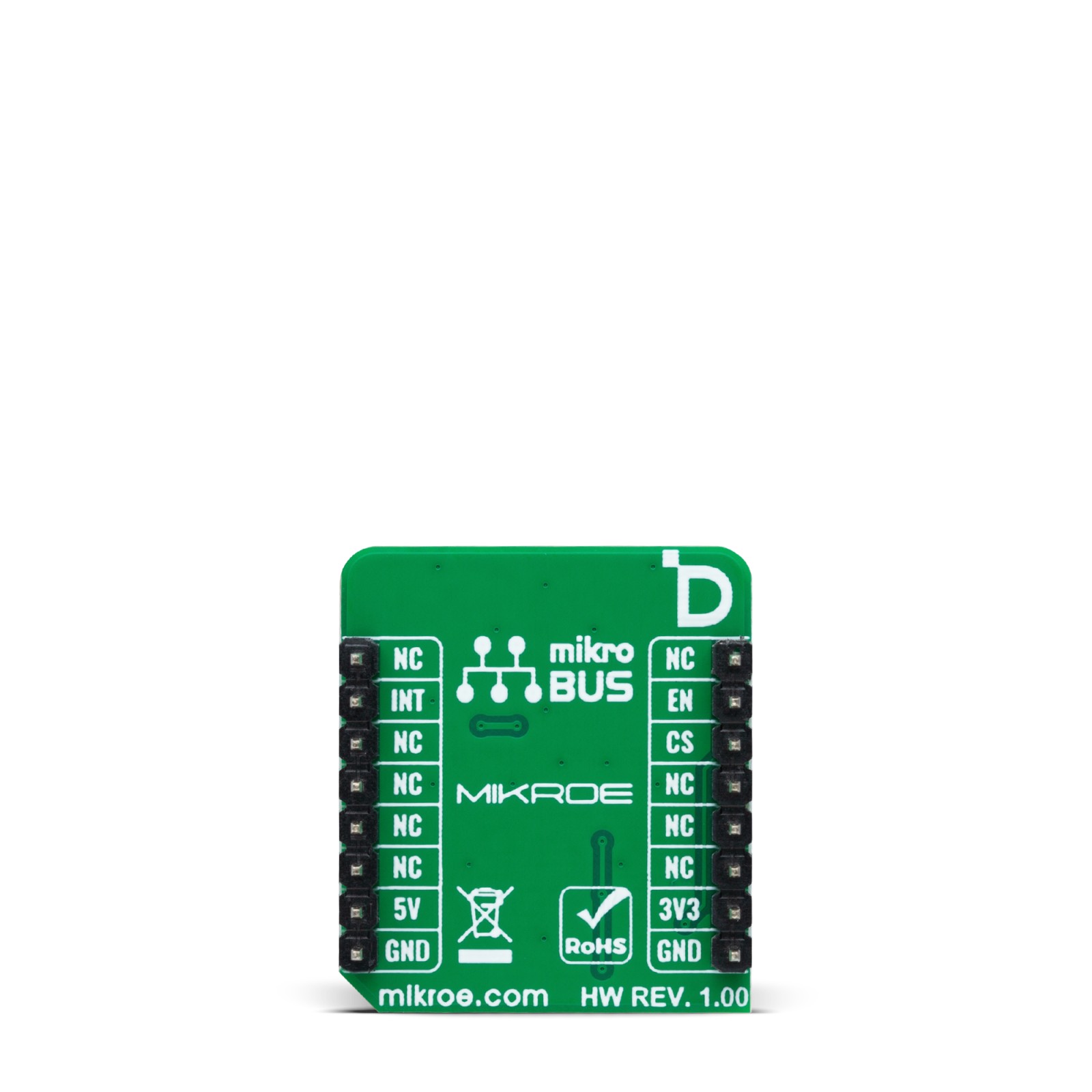
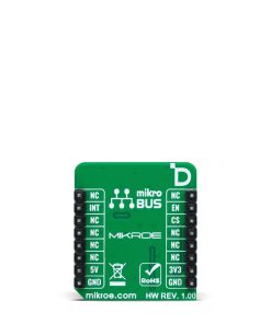
This table shows how the pinout on IR Eclipse 2 Click corresponds to the pinout on the mikroBUS™ socket (the latter shown in the two middle columns).
Onboard settings and indicators
Label | Name | Default | Description |
---|---|---|---|
LD1 | PWR | – | Power LED Indicator |
LD2 | INT | – | Object Detection LED Indicator |
JP1 | VIO SEL | Left | Logic Voltage Level Selection 3V3/5V: Left position 3V3, Right position 5V |
IR Eclipse 2 Click electrical specifications
Description | Min | Typ | Max | Unit |
---|---|---|---|---|
Supply Voltage | 3.3 | – | 5 | V |
Sensing Slot Width | – | 3 | – | mm |
Detector Wavelength | – | 940 | – | nm |
Software Support
We provide a library for the IR Eclipse 2 Click as well as a demo application (example), developed using MIKROE compilers. The demo can run on all the main MIKROE development boards.
Package can be downloaded/installed directly from NECTO Studio Package Manager(recommended), downloaded from our LibStock™ or found on Mikroe github account.
Library Description
This library contains API for IR Eclipse 2 Click driver.
Key functions
-
ireclipse2_get_state
This function detecting eclipse states. -
ireclipse2_enable
This function enables the transmitter of the photo-microsensor. -
ireclipse2_disable
This function disables the transmitter of the photo-microsensor.
Example Description
This example demonstrates the use of the IR Eclipse 2 Click board by detecting eclipse states.
void application_task ( void )
{
ecls_state = ireclipse2_get_state( &ireclipse2 );
if ( cmp_state != ecls_state )
{
if ( IRECLIPSE2_STATE_ECLIPSE == ecls_state )
{
log_printf( &logger, " Counter: %un", cnt );
cnt++;
}
cmp_state = ecls_state;
}
}
The full application code, and ready to use projects can be installed directly from NECTO Studio Package Manager(recommended), downloaded from our LibStock™ or found on Mikroe github account.
Other Mikroe Libraries used in the example:
- MikroSDK.Board
- MikroSDK.Log
- Click.IREclipse2
Additional notes and informations
Depending on the development board you are using, you may need USB UART click, USB UART 2 Click or RS232 Click to connect to your PC, for development systems with no UART to USB interface available on the board. UART terminal is available in all MIKROE compilers.
mikroSDK
This Click board™ is supported with mikroSDK – MIKROE Software Development Kit. To ensure proper operation of mikroSDK compliant Click board™ demo applications, mikroSDK should be downloaded from the LibStock and installed for the compiler you are using.
For more information about mikroSDK, visit the official page.