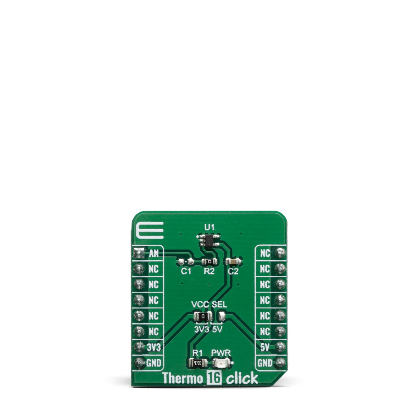
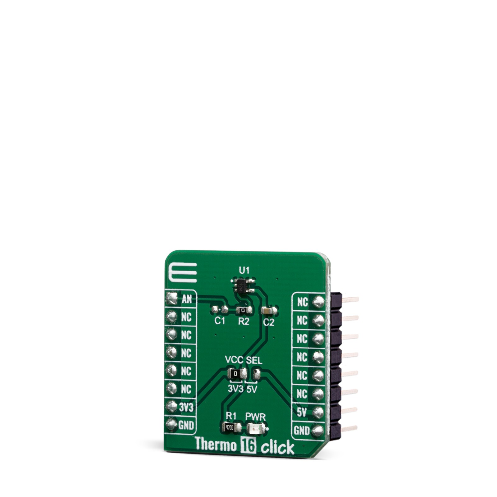
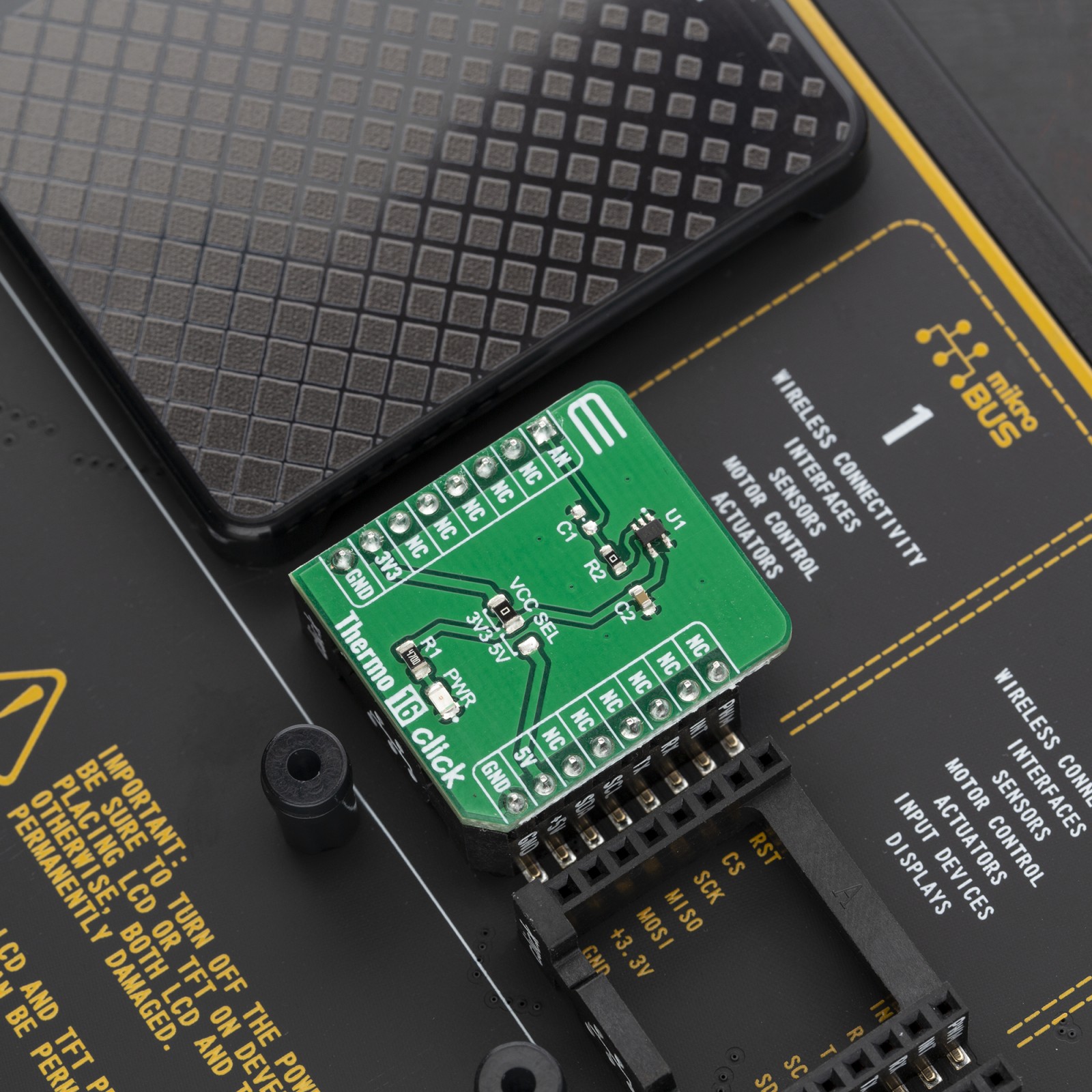
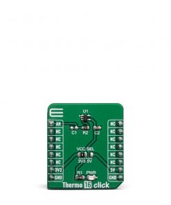
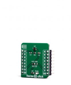
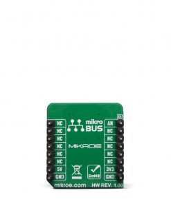
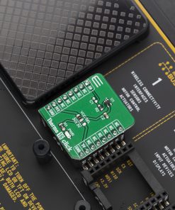
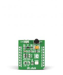
The Click board™ is specially designed so it retains the specified characteristics of the sensor IC. Equipped with this sophisticated, accurate and simple to use sensor IC, it can be used for measuring and monitoring the temperature in a whole range of applications, such as the PC case and other internal components temperature monitoring, office equipment, automotive infotainment and entertainment systems thermal monitoring, general purpose thermal measurement, and similar digital thermal measurement applications, that require a precise thermal measurement.
How does it work?
The active temperature sensing component on Thermo 16 click is the TMP235, a high accuracy temperature sensor IC Texas Instruments. The Click board™ itself has a reasonably small number of components because most of the measurement circuitry is already integrated on the TMP235 sensor. This sensor has many features that make it a perfect solution for small designs such as the Ambient 7 Click board™, and one of these features is certainly its high level of integration.
The TMP23X devices are a family of precision CMOS integrated-circuit linear analog temperature sensors with an output voltage proportional to temperature engineers can use in multiple analog temperature sensing applications. The TMP235 temperature sensor have an accuracy from 0°C to 70°C of ±1.25°C and provides a positive slope output of 10 mV/°C over the full –40°C to +150°C temperature range.
It is worth to mention that the TMP235 has extremely low power consumption – 9 μA (Typical). This makes Thermo 16 click a perfect solution for the development of the IoT, wearable and portable applications, logging devices, industrial and health-related time metering applications, and all the other applications that require an accurate temperature measurement for their operation.
An analog signal from the thermal sensor, from Vout pin is routed to the AN pin of the mikroBUS™ socket. On the path from the sensor to the mikroBUS™ socket, R2 and C1 are forming the RC filter. R2 is 0 ohm by default, but the user can increase the resistance in order to find a perfect match for desired purpose. Note that higher resistance may help filter any noise in signal, but may also increase the sensor response time, so when tuning the RC filter, it is crucial to find the ideal balance between these two.
The TMP235 operates at power supply range from 2.3 V to 5.5 V. Thus, Thermo 16 click has the power supply selection jumper onboard, named VCC SEL. That way, the user can switch between 3.3V and 5V for sensor power supply.
Specifications
Type
Temperature & humidity
Applications
PC case and other internal components temperature monitoring, office equipment, automotive infotainment and entertainment systems thermal monitoring, general purpose thermal measurement, and similar
On-board modules
TMP235, High-Accuracy Analog Output Temperature Sensors
Key Features
Analog signal output, low power consumption, compact sensor size
Interface
Analog
Feature
No ClickID
Compatibility
mikroBUS™
Click board size
S (28.6 x 25.4 mm)
Input Voltage
3.3V or 5V
Pinout diagram
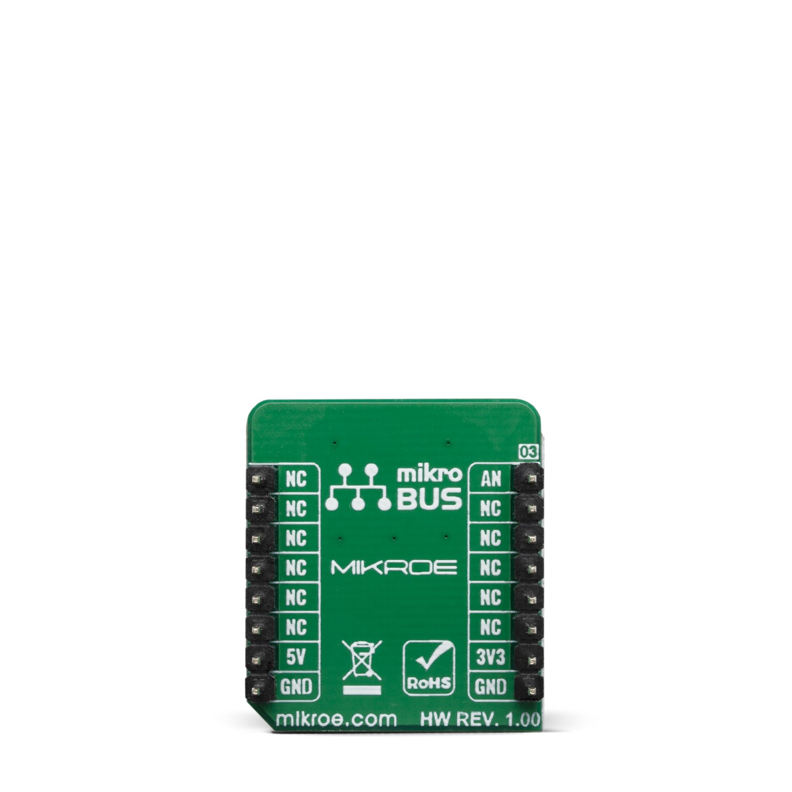
This table shows how the pinout on Thermo 16 click corresponds to the pinout on the mikroBUS™ socket (the latter shown in the two middle columns).
Onboard settings and indicators
Label | Name | Default | Description |
---|---|---|---|
JP1 | VCC SEL | Left | Power supply voltage selection: left position 3V3, right position 5V |
LD1 | PWR | – | Power LED indicator |
Thermo 16 click maximum ratings
Description | Min | Typ | Max | Unit |
---|---|---|---|---|
Temperature Range (accuracy ±1˚C) | 0 | – | 70 | °C |
Temperature Range (accuracy ±2˚C) | -40 | – | +150 | °C |
Supply voltage | 2.3 | – | 5.5 | V |
Operating current | – | – | 17 | μA |
Software Support
We provide a library for the Thermo 16 Click on our LibStock page, as well as a demo application (example), developed using MikroElektronika compilers. The demo can run on all the main MikroElektronika development boards.
Library Description
The library includes function for read Temperature data and function for system(board) configuration. The user also has the function for ADC init and read ADC data.
Key functions:
float thermo16_getTemperature(uint32_t adcValue, uint8_t tempIn)
– Get Temperature data.void thermo16_systemConfig(T_THERMO16_SYS_CONFIG *config)
– System (board) config.uint32_t thermo16_adcRead()
– Get ADC data.
Examples description
The application is composed of three sections :
- System Initialization – Sets AN pin as INPUT.
- Application Initialization – Initializes GPIO driver init, system configuration and ADC init.
- Application Task – Reads the ADC value and converts ADC data to the Temperature data. This temp data logs on the USBUART every 1500ms.
void applicationTask() { uint32_t ADC_value; float Temperature; char demoText[ 50 ]; ADC_value = thermo16_adcRead(); Temperature = thermo16_getTemperature(ADC_value, _THERMO16_TEMP_IN_CELSIUS); FloatToStr(Temperature, demoText); mikrobus_logWrite(" Temperature: ", _LOG_TEXT); mikrobus_logWrite(demoText, _LOG_LINE); mikrobus_logWrite( " ------------------------ ", _LOG_LINE); Delay_ms( 1500 ); }
The full application code, and ready to use projects can be found on our LibStock page.
Other mikroE Libraries used in the example:
- ADC
- UART
- Conversions
Additional notes and informations
Depending on the development board you are using, you may need USB UART click, USB UART 2 click or RS232 click to connect to your PC, for development systems with no UART to USB interface available on the board. The terminal available in all MikroElektronika compilers, or any other terminal application of your choice, can be used to read the message.
mikroSDK
This Click board™ is supported with mikroSDK – MikroElektronika Software Development Kit. To ensure proper operation of mikroSDK compliant Click board™ demo applications, mikroSDK should be downloaded from the LibStock and installed for the compiler you are using.
For more information about mikroSDK, visit the official page.