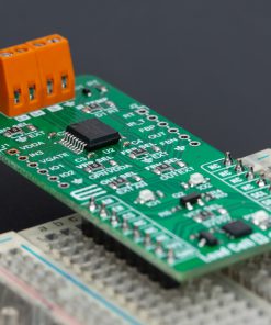
How does it work?
Load Cell 8 Click is based on the ZSC31050, an advanced differential sensor signal conditioner from Renesas. The ZSC31050 provides precise amplification and sensor-specific corrections for bridge and temperature sensor signals. Featuring a 16-bit RISC MCU, it runs a polynomial correction algorithm to digitally compensate for sensor offset, sensitivity, temperature changes, and non-linearity. It supports a wide range of resistive bridge sensors with signal spans from 1mV/V to 275mV/V, making it ideal for industrial, medical, and consumer applications. This IC is made for sensors that measure pressure, force, and position, among others.
The ZSC31050 integrates both analog and digital pathways, where the analog section is configured differentially to enhance noise rejection. This setup enables the amplification of both positive and negative signals within the common mode range. The differential signal undergoes initial amplification by a programmable gain amplifier (PGA), followed by multiplexing (MUX) that channels signals from various sources to the ADC for digital conversion. Using a standard I2C interface, Load Cell 8 Click communicates with the host MCU in order to program a set of calibration coefficients into an on-chip EEPROM. It supports communication frequencies up to 400kHz and uses an EN pin of the mikroBUS™ socket as a IC enabling function.
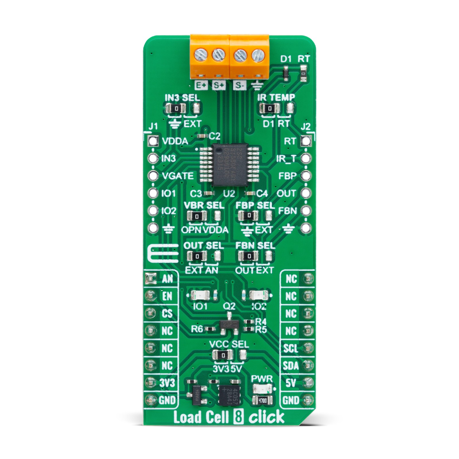
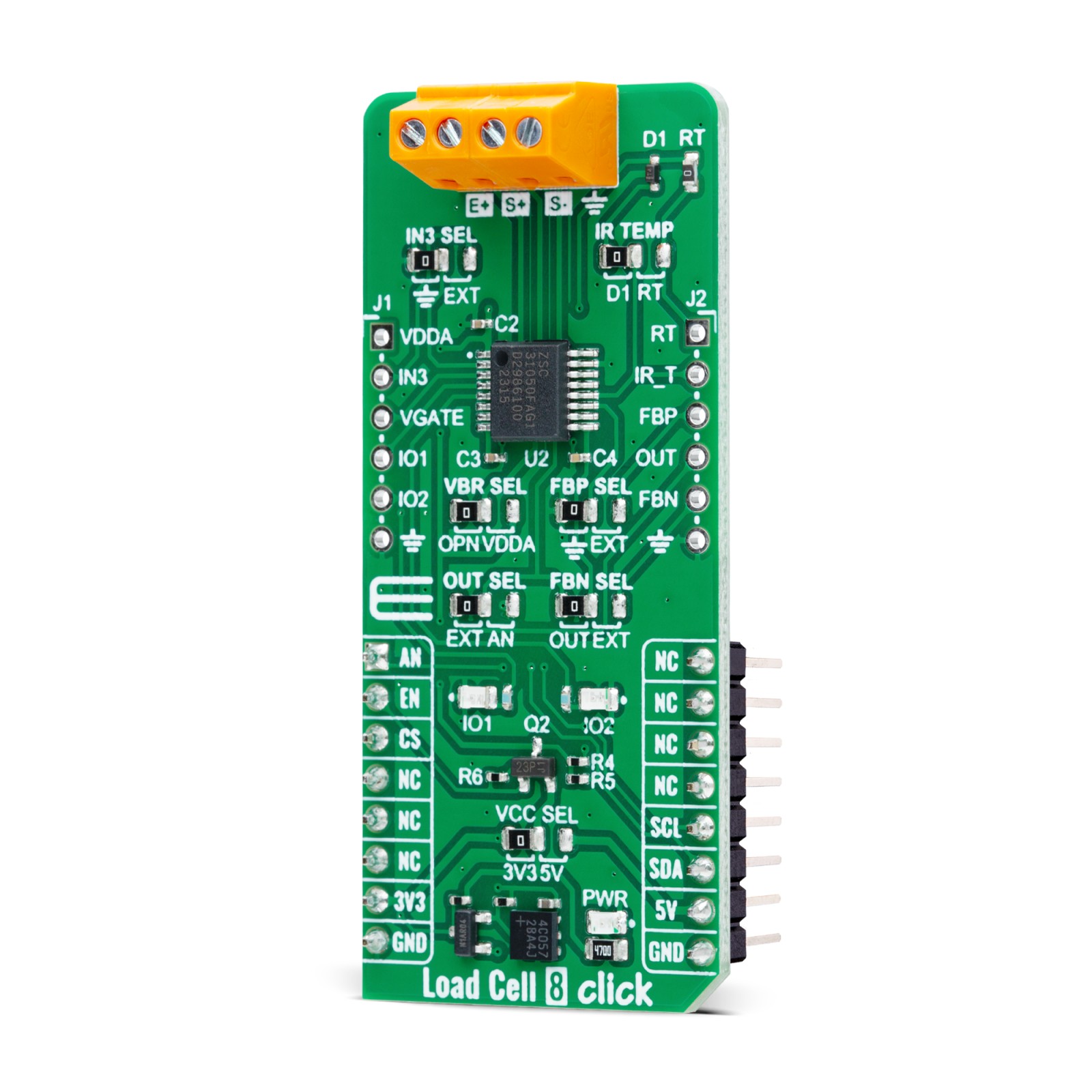
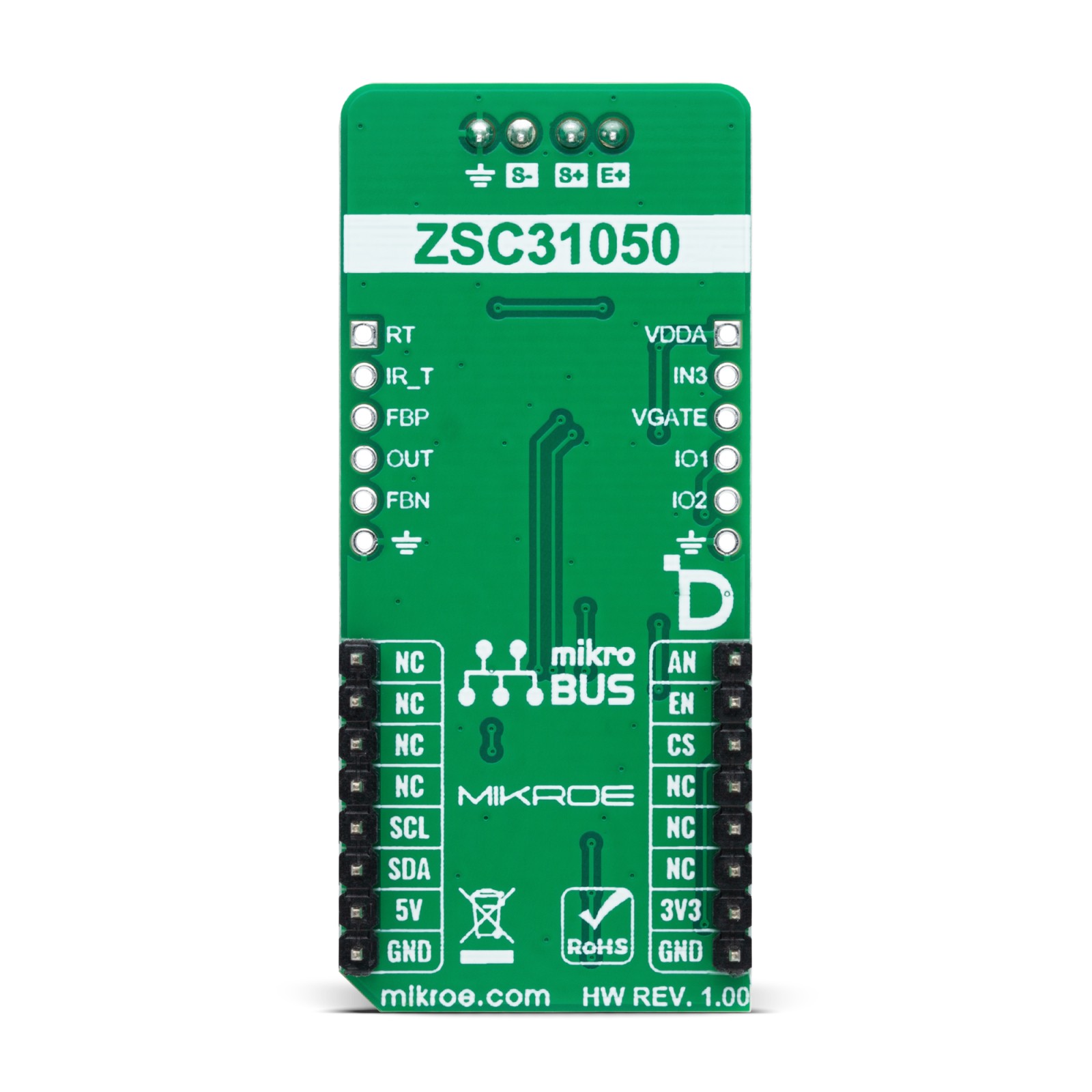
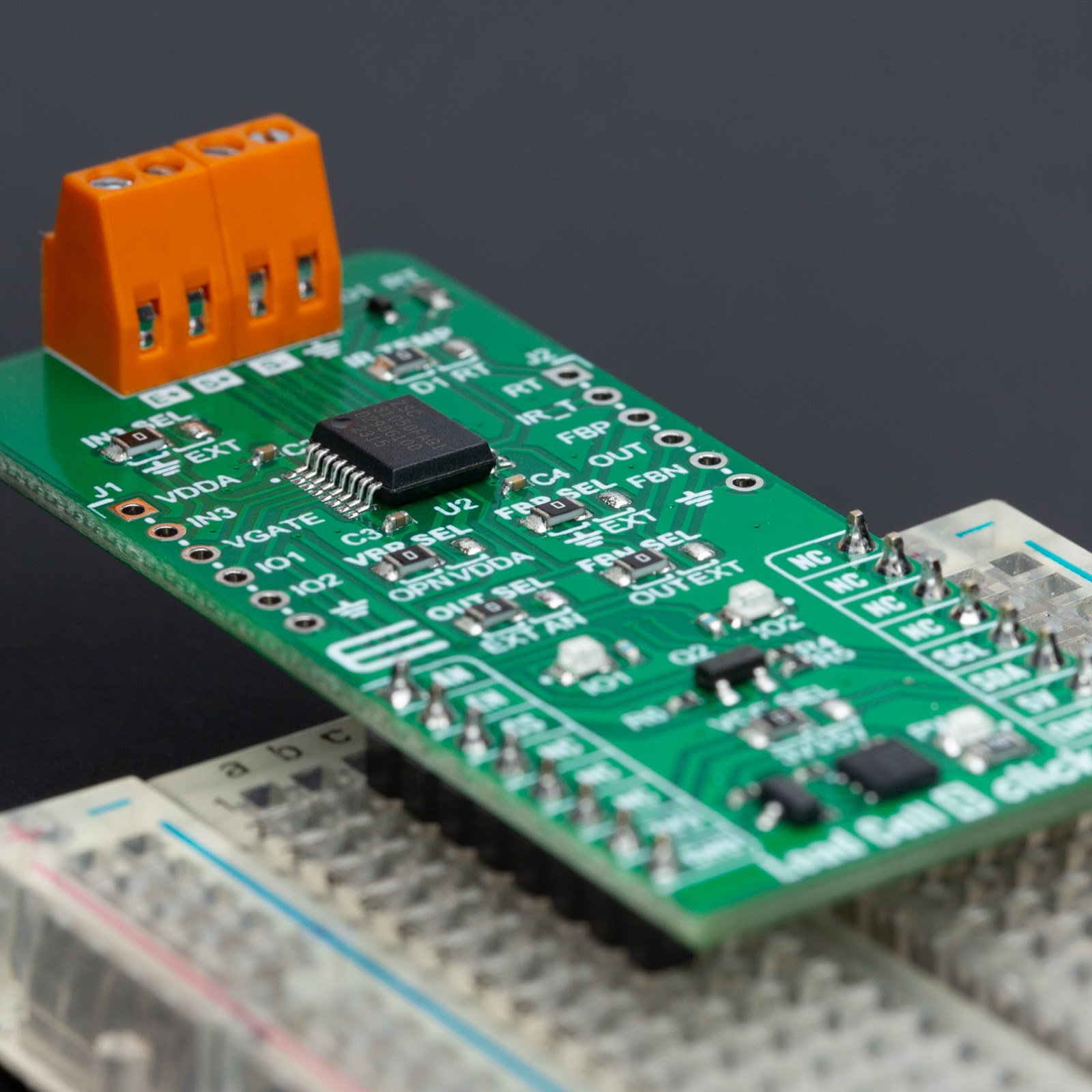
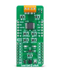
Load Cell 8 Click offers diverse output modes such as analog voltage, current loop (4 to 20 mA), and PWM. The route of the output signal is selectable via the OUT SEL jumper, directing it through either the AN pin on the mikroBUS™ socket or the OUT pin on the unpopulated J2 header for external applications. Other jumpers include VBR SEL for selecting the ADC’s external reference voltage, which is recommended for ratiometric bridges when set to VDDA position, and IN3 SEL, which allows for the use of the IN3 pin for external voltage mode operations, external clocking, or as a ratiometric signal measurement point.
This Click board™ can also interface with temperature sensors via the IR TEMP jumper, which selects the input for temperature-related measurements essential for calibration and correction processes. Selection is made between an internal sensor in the form of a D1 diode or an external using an external resistor for temperature measurement that needs to be populated on RT. It also includes configurable IO1 and IO2 LEDs for indicating alarm statuses and unpopulated headers, J1 and J2, with various signals, some as duplicates from already used signals of the ZSC31050 and some for use as external ones.
This Click board™ can operate with either 3.3V or 5V logic voltage levels selected via the VCC SEL jumper. This way, both 3.3V and 5V capable MCUs can use the communication lines properly. Also, this Click board™ comes equipped with a library containing easy-to-use functions and an example code that can be used as a reference for further development.
Specifications
Type
Force
Applications
Ideal or measuring pressure, force, torque, and position in monitoring and control systems
On-board modules
ZSC31050 – advanced differential sensor signal conditioner from Renesas
Key Features
Digital compensation of sensor offset, sensitivity, temperature drift, and non-linearity, accommodates nearly all bridge sensors via PGA and programmable ADC, sensor connections check and aging detection, temperature compensation, output options, and more
Interface
Analog,I2C
Feature
ClickID
Compatibility
mikroBUS™
Click board size
L (57.15 x 25.4 mm)
Input Voltage
3.3V or 5V
Pinout diagram
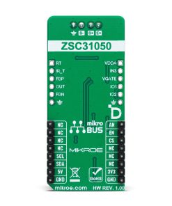
This table shows how the pinout on Load Cell 8 Click corresponds to the pinout on the mikroBUS™ socket (the latter shown in the two middle columns).
Onboard settings and indicators
Label | Name | Default | Description |
---|---|---|---|
LD1 | PWR | – | Power LED Indicator |
LD2-LD3 | IO1-IO2 | – | User-Configurable Alarm LED Indicators |
JP1 | VCC SEL | Left | Logic Voltage Level Selection 3V3/5V: Left position 3V3, Right position 5V |
JP2 | VBR SEL | Left | ADC External Reference Voltage Selection OPN/VDDA: Left position OPN, Right position VDDA |
JP3 | OUT SEL | Left | Output Signal Route Selection EXT/AN: Left position EXT, Right position AN |
JP4 | IR TEMP | Left | Temperature Sensor Selection D1/RT: Left position D1, Right position RT |
JP5 | FBN SEL | Left | Negative Feedback Output Stage Selection OUT/EXT: Left position OUT, Right position EXT |
JP6 | IN3 SEL | Left | External Resistive Temp. Sesnor / Clock Input GND/EXT: Left position GND, Right position EXT |
JP7 | FBP SEL | Left | Positive Feedback Output Stage Selection GND/EXT: Left position GND, Right position EXT |
Load Cell 8 Click electrical specifications
Description | Min | Typ | Max | Unit |
---|---|---|---|---|
Receiver inputs voltage range | 3.3 | – | 5 | V |
Bridge Sensor Signal Range | 1 | – | 275 | mV/V |
Software Support
We provide a library for the Load Cell 8 Click as well as a demo application (example), developed using MIKROE compilers. The demo can run on all the main MIKROE development boards.
Package can be downloaded/installed directly from NECTO Studio Package Manager(recommended), downloaded from our LibStock™ or found on Mikroe github account.
Library Description
This library contains API for Load Cell 8 Click driver.
Key functions
-
loadcell8_read_raw_adc
This function reads raw ADC value by using I2C serial interface. -
loadcell8_tare_scale
This function calculates the cell_data which is the raw ADC readings of the empty container by using I2C serial interface. -
loadcell8_calibration_weight
This function calibrates the weight by calculating the cell_data for the input calibration weight by using I2C serial interface.
Example Description
This example demonstrates the use of Load Cell 8 click by measuring the weight in grams of the goods from the load cell sensor connected to the click board.
void application_task ( void )
{
float weight_g = 0;
if ( LOADCELL8_OK == loadcell8_get_weight( &loadcell8, &cell_data, &weight_g ) )
{
log_printf( &logger, " Weight : %.2f g rn", weight_g );
}
Delay_ms( 100 );
}
The full application code, and ready to use projects can be installed directly from NECTO Studio Package Manager(recommended), downloaded from our LibStock™ or found on Mikroe github account.
Other Mikroe Libraries used in the example:
- MikroSDK.Board
- MikroSDK.Log
- Click.LoadCell8
Additional notes and informations
Depending on the development board you are using, you may need USB UART click, USB UART 2 Click or RS232 Click to connect to your PC, for development systems with no UART to USB interface available on the board. UART terminal is available in all MIKROE compilers.
mikroSDK
This Click board™ is supported with mikroSDK – MIKROE Software Development Kit. To ensure proper operation of mikroSDK compliant Click board™ demo applications, mikroSDK should be downloaded from the LibStock and installed for the compiler you are using.
For more information about mikroSDK, visit the official page.