DTMF Click
R940.00 ex. VAT
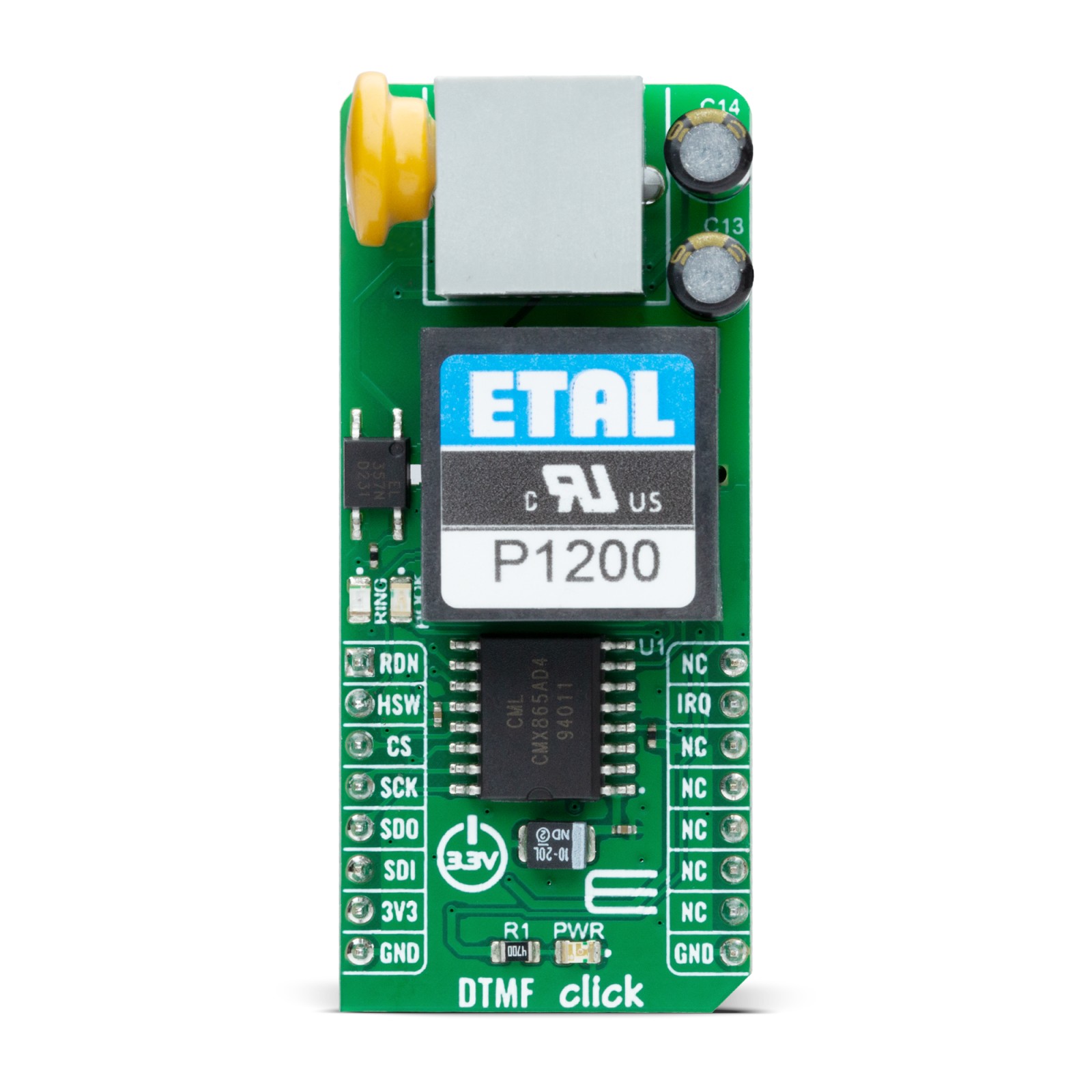
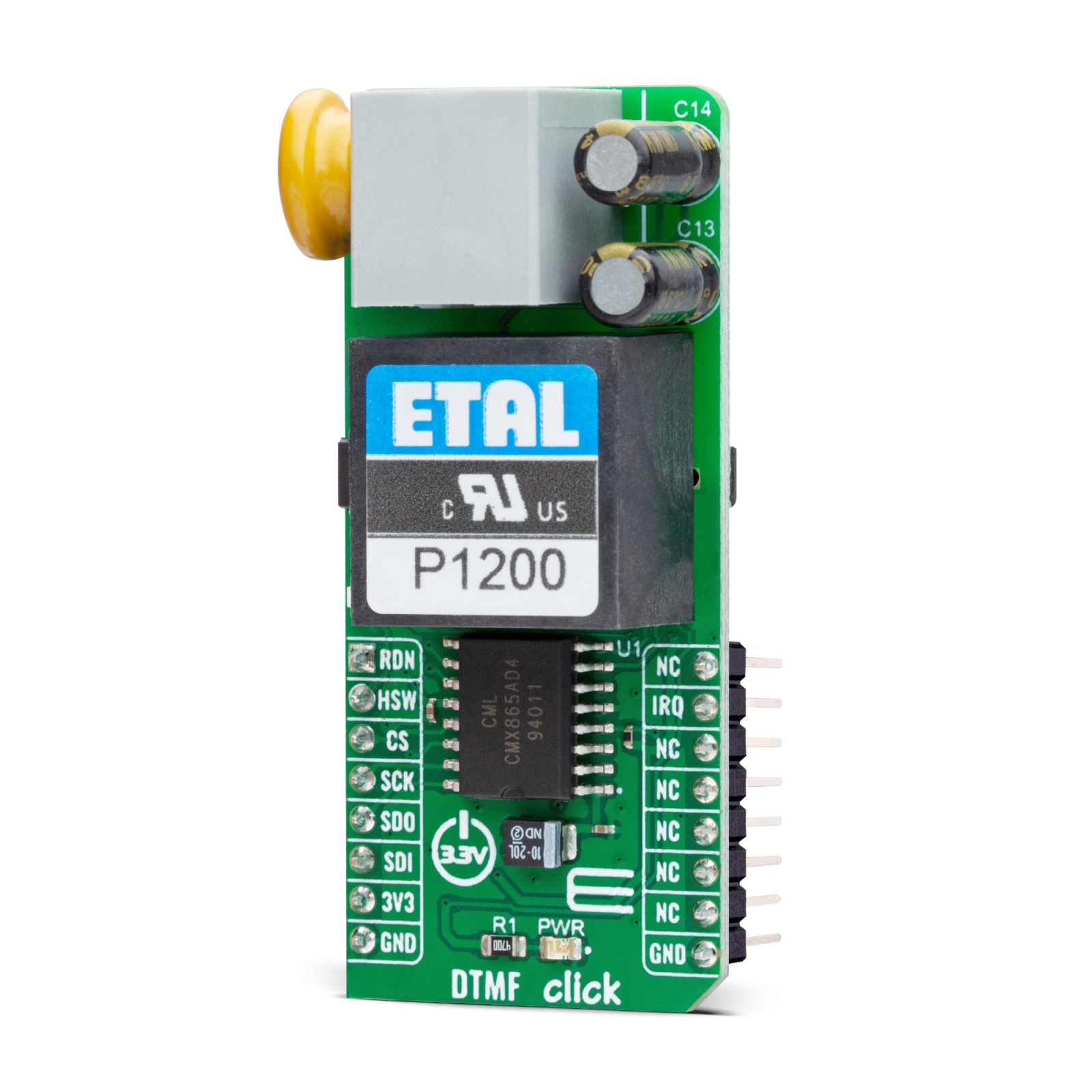
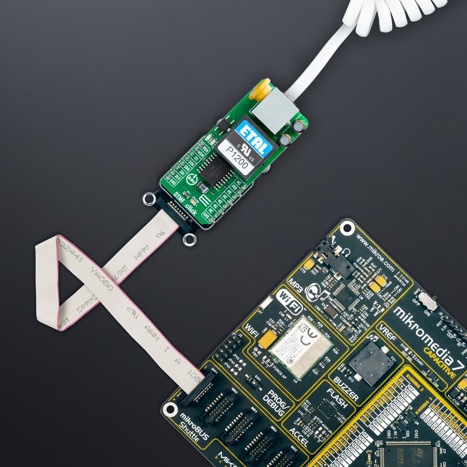
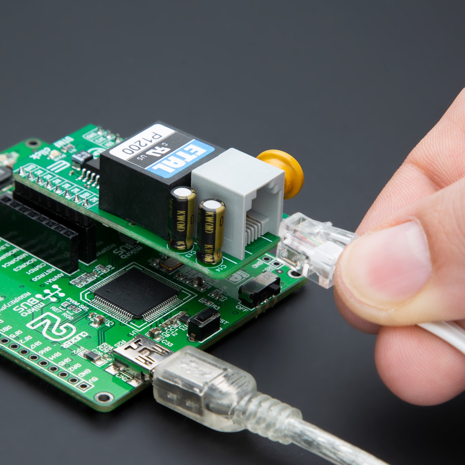
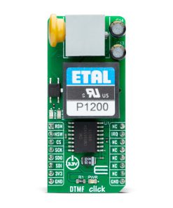
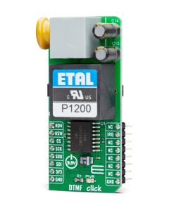
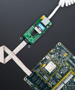
DTMF Click is a compact add-on board designed for projects that demand reliable telephony interactions. This board features the CMX865A, a DTMF Codec/FSK Combo multi-standard modem from CML Micro. The CMX865A excels in encoding and decoding DTMF signals, alongside supporting FSK data transmission compatible with V.23, V.21, Bell 103, and Bell 202 standards, making it versatile for various telephony applications. It’s particularly adept at enabling dual-mode operations for transmitting and receiving data, ensuring high fidelity in signal processing and resistance to voice falsing. Ideal for security systems, automated response services, and IoT devices requiring telephonic interaction, DTMF Click provides a solution for developers looking to incorporate reliable telecommunication capabilities.
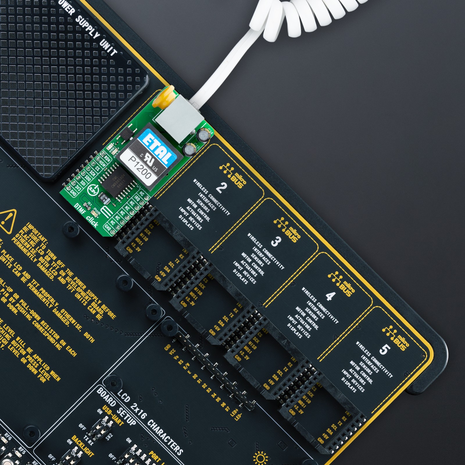
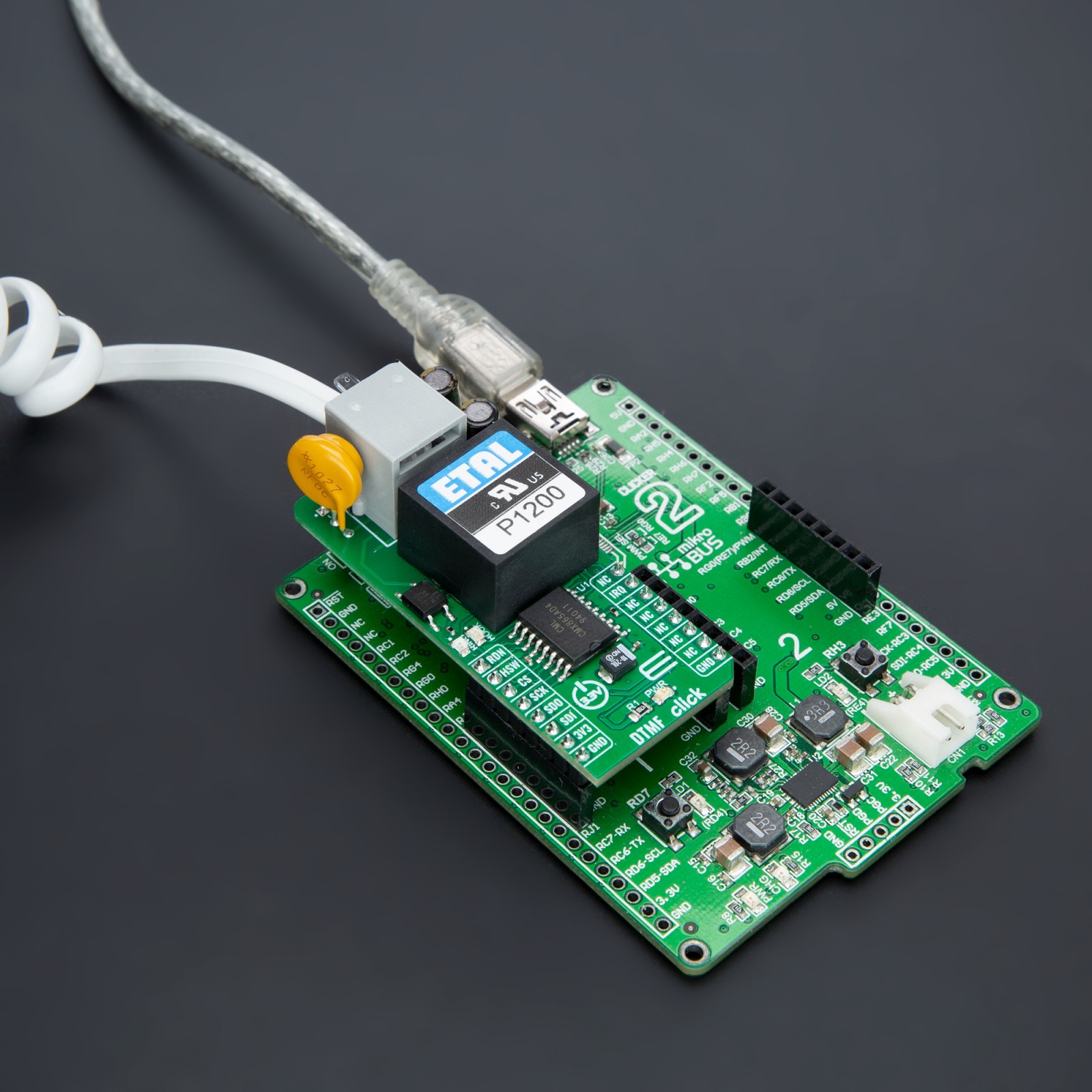
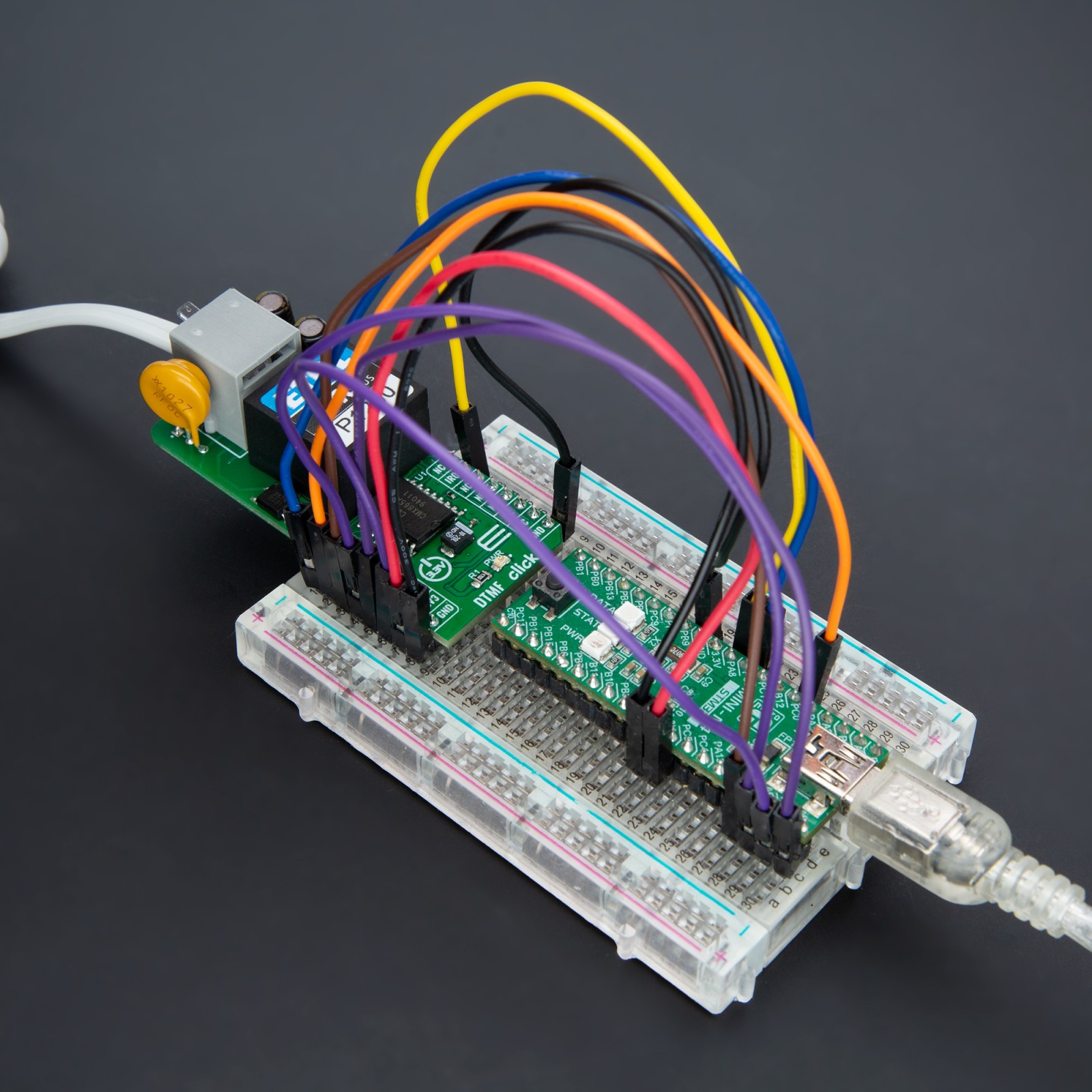
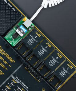
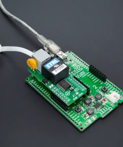
DTMF Click board™ is supported by a mikroSDK compliant library, which includes functions that simplify software development. This Click board™ comes as a fully tested product, ready to be used on a system equipped with the mikroBUS™ socket.
Stock: Lead-time applicable.
| 5+ | R893.00 |
| 10+ | R846.00 |
| 15+ | R799.00 |
| 20+ | R768.92 |
NOTE: To ensure the DTMF Click board™ meets global telecom isolation standards, it is essential to implement appropriate isolation measures. Using any SPI Isolator Click board™ is advisable to enhance the safety and reliability of your project and should be positioned between the line side of the DTMF Click and the system in use. These precautions help comply with international telecom standards, which may require isolation up to 6500V in some countries.
Warning: Telecom isolation requirements vary significantly across different countries. Always consult the telecom regulations specific to your country before connecting to the line. The users are responsible for ensuring compliance with local telecom standards and regulations.
How does it work?
DTMF Click is based on the CMX865A, a high-performance DTMF Codec/FSK Combo multi-standard modem from CML Micro. This Click board™ stands out for its integration of both an industrial standard DTMF encoder/decoder and a versatile FSK modem, catering to a variety of telephone connectivity and interconnect applications. The CMX865A’s ability to handle basic call setups and progress functionalities, coupled with its capacity for data signaling, makes it suitable for remote control, status notification, and data acquisition across numerous fields.

As mentioned, the CMX865A combines a high-quality DTMF decoder known for its resistance to voice falsing and a multifaceted FSK modem that supports standards like V.23, V.21, Bell 103, and Bell 202. Users benefit from its dual operational modes, which are programmable for transmission and reception, allowing for the transmission of programmed signals, simple melodies, or modem tones. Its applicability extends to security systems that rely on DTMF for access control, automated response services for customer interaction, and IoT devices requiring remote control over telephony networks. Additionally, its on-chip line driver, hybrid, and receiver circuits, complemented by external components and a P1200 transformer, offer a complete, fully isolated line interface solution.
Data and control exchanges between the CMX865A and the host MCU are made through a C-BUS interface, compatible with a standard 4-wire SPI interface of the mikroBUS™ socket. The board also uses the mikroBUS™ socket’s RDN pin and a red RING LED to indicate ringing signals and the IRQ pin for interrupt requests related to call states like busy, dialing, and connected statuses. The HSW pin, alongside a blue HOOK LED, also serves as a hookswitch to manage the line interface’s connectivity status (0-OFF, 1-ON). An additional feature of the CMX865A is the Powersave mode, which conserves energy by deactivating all circuits except the essential C-BUS (SPI) interface.
This Click board™ can be operated only with a 3.3V logic voltage level. The board must perform appropriate logic voltage level conversion before using MCUs with different logic levels. Also, it comes equipped with a library containing functions and an example code that can be used as a reference for further development.
Specifications
Type
Signal Processing
Applications
Ideal for security systems, automated response services, and IoT devices requiring telephonic interaction
On-board modules
CMX865A – DTMF Codec/FSK Combo multi-standard modem from CML Micro
Key Features
High-quality telephony communication, DTMF encoding/decoding and FSK data transmission, multi-standard FSK compatibility, resistance to voice falsing and noise interference, dual-mode operation, low power consumption, and more
Interface
SPI
Feature
ClickID
Compatibility
mikroBUS™
Click board size
L (57.15 x 25.4 mm)
Input Voltage
3.3V
Pinout diagram
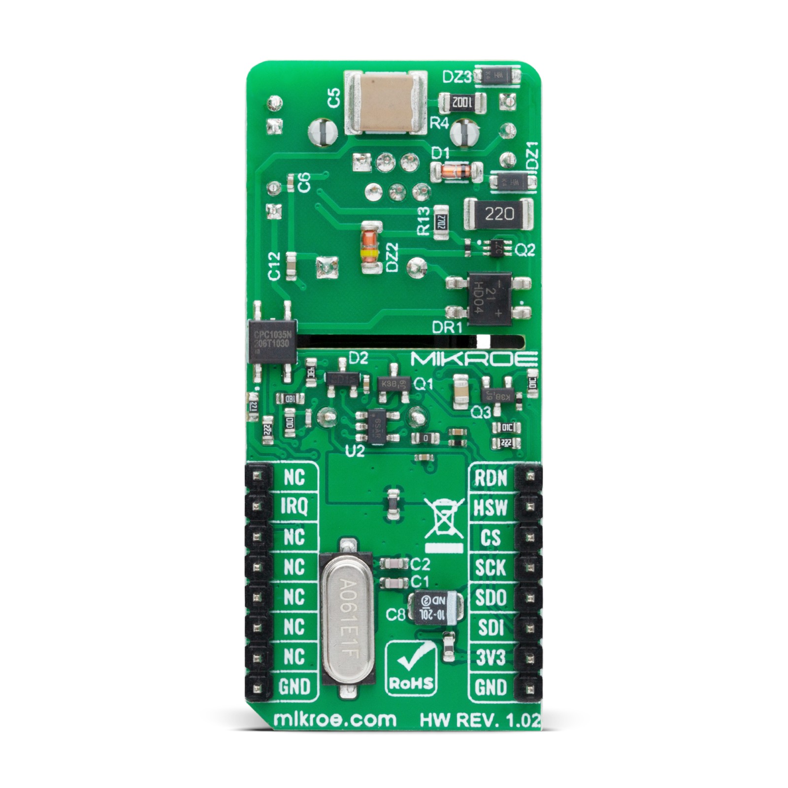
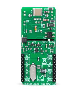
This table shows how the pinout on DTMF Click corresponds to the pinout on the mikroBUS™ socket (the latter shown in the two middle columns).
Onboard settings and indicators
| Label | Name | Default | Description |
|---|---|---|---|
| LD1 | PWR | – | Power LED Indicator |
| LD2 | RING | – | Ring LED Indicator |
| LD3 | HOOK | – | Board Hook State LED Indicator |
DTMF Click electrical specifications
| Description | Min | Typ | Max | Unit |
|---|---|---|---|---|
| Supply Voltage | – | 3.3 | – | V |
Software Support
We provide a library for the DTMF Click as well as a demo application (example), developed using MIKROE compilers. The demo can run on all the main MIKROE development boards.
Package can be downloaded/installed directly from NECTO Studio Package Manager (recommended), downloaded from our LibStock™ or found on Mikroe github account.
Library Description
This library contains API for DTMF Click driver.
Key functions
-
dtmf_handshake_initThis function performs a handshake init which resets the device settings to default. -
dtmf_dialThis function dials the selected number by alternating between DTMF and No-tone. -
dtmf_send_messageThis function sends an array of bytes via V.23 FSK 1200bps modem in start-stop 8.1 mode.
Example Description
This example demonstrates the use of DTMF click board by showing the communication between the two click boards connected to PBX system.
void application_task ( void )
 {
     uint8_t state = DTMF_STATE_IDLE;
     uint32_t time_cnt = 0;
     uint8_t msg_cnt = 0;

     dtmf_handshake_init ( &dtmf );

 #if ( DEMO_APP == APP_DIALING )
     log_printf( &logger, "rn Hook OFFrn" );
     dtmf_hook_off ( &dtmf );
     Delay_ms ( 4000 );
     log_printf( &logger, " Dial: %srn", ( char * ) DIAL_NUMBER );
     dtmf_dial ( &dtmf, DIAL_NUMBER );
     dtmf.rx_mode &= DTMF_RX_LEVEL_MASK; // No change in rx level setting
     dtmf.rx_mode |= ( DTMF_RX_MODE_DTMF_TONES | DTMF_RX_TONE_DETECT_CALL_PROG );
     dtmf_set_receive_mode ( &dtmf, dtmf.rx_mode );
     for ( ; ; )
     {
         Delay_ms ( 1 );
         if ( !dtmf_get_irq_pin ( &dtmf ) )
         {
             time_cnt = 0;
             state = DTMF_STATE_IRQ_SET;
         }
         if ( ( DTMF_STATE_IRQ_SET == state ) && !dtmf_call_progress ( &dtmf ) )
         {
             if ( time_cnt < DTMF_TIMING_BUSY )
             {
                 log_printf( &logger, " Busyrn" );
                 break;
             }
             else if ( time_cnt < DTMF_TIMING_DISCONNECTED )
             {
                 log_printf( &logger, " Disconnectedrn" );
                 break;
             }
             else if ( time_cnt < DTMF_TIMING_RINGING )
             {
                 log_printf( &logger, " Ringingrn" );
                 state = DTMF_STATE_RINGING;
             }
         }
         if ( ( DTMF_STATE_RINGING == state ) && ( time_cnt > DTMF_TIMING_CALL_PROGRESS ) )
         {
             log_printf( &logger, " Call in progressrn" );
             state = DTMF_STATE_CALL_IN_PROGRESS;
             time_cnt = 0;
         }
         if ( ( DTMF_STATE_CALL_IN_PROGRESS == state ) && !( time_cnt % DTMF_TIMING_SEND_MESSAGE ) )
         {
             log_printf( &logger, " Send message %urn", ( uint16_t ) msg_cnt++ );
             dtmf_send_message ( &dtmf, TEXT_TO_SEND, strlen ( TEXT_TO_SEND ) );
         }
         if ( time_cnt++ > DTMF_TIMEOUT_CALL_PROGRESS )
         {
             log_printf( &logger, " Timeoutrn" );
             break;
         }
     }
     log_printf( &logger, " Hook ONrn" );
     dtmf_hook_on ( &dtmf );
     Delay_ms ( 4000 );
 #elif ( DEMO_APP == APP_ANSWERING )
     uint8_t rx_data = 0;
     uint8_t msg_end_buff[ 2 ] = { 0 };

     log_printf( &logger, "rn Waiting for a call...rn" );

     while ( dtmf_get_rdn_pin ( &dtmf ) );

     Delay_ms ( 1000 );
     log_printf( &logger, " Hook OFFrn" );
     dtmf_hook_off ( &dtmf );
     Delay_ms ( 1000 );
     log_printf( &logger, " Waiting for %u messages...rn", ( uint16_t ) NUM_MESSAGES );
     dtmf.rx_mode &= DTMF_RX_LEVEL_MASK; // No change in rx level setting
     dtmf.rx_mode |= ( DTMF_RX_MODE_V23_FSK_1200 | DTMF_RX_USART_START_STOP | DTMF_RX_DATA_PARITY_8_NO_PAR );
     dtmf_set_receive_mode ( &dtmf, dtmf.rx_mode );

     for ( ; ; )
     {
         Delay_ms ( 1 );
         if ( !dtmf_get_irq_pin ( &dtmf ) )
         {
             if ( DTMF_STATE_IDLE != state )
             {
                 log_printf( &logger, "rn Disconnectedrn" );
                 break;
             }
             log_printf( &logger, " Message %u: ", ( uint16_t ) msg_cnt );
             state = DTMF_STATE_IRQ_SET;
             time_cnt = 0;
         }
         if ( ( DTMF_STATE_IRQ_SET == state ) && !( time_cnt % DTMF_TIMING_RX_READY ) )
         {
             if ( dtmf_unscram_1s_det ( &dtmf ) && dtmf_rx_ready ( &dtmf ) )
             {
                 dtmf_receive_data ( &dtmf, &rx_data );
                 log_printf( &logger, "%c", ( uint16_t ) rx_data );
                 if ( 'r' == rx_data )
                 {
                     msg_end_buff[ 0 ] = rx_data;
                 }
                 else if ( 'n' == rx_data )
                 {
                     msg_end_buff[ 1 ] = rx_data;
                 }
                 else
                 {
                     msg_end_buff[ 0 ] = 0;
                     msg_end_buff[ 1 ] = 0;
                 }
             }
             if ( ( 'r' == msg_end_buff[ 0 ] ) && ( 'n' == msg_end_buff[ 1 ] ) )
             {
                 msg_end_buff[ 0 ] = 0;
                 msg_end_buff[ 1 ] = 0;
                 state = DTMF_STATE_IDLE;
                 if ( NUM_MESSAGES == ++msg_cnt )
                 {
                     Delay_ms ( 100 );
                     log_printf( &logger, " Terminate callrn" );
                     Delay_ms ( 100 );
                     break;
                 }
             }
         }
         if ( time_cnt++ > DTMF_TIMING_WAIT_FOR_MESSAGE )
         {
             log_printf( &logger, "rn Timeoutrn" );
             break;
         }
     }
     log_printf( &logger, " Hook ONrn" );
     dtmf_hook_on ( &dtmf );
     Delay_ms ( 4000 );
 #endif
 }
The full application code, and ready to use projects can be installed directly from NECTO Studio Package Manager (recommended), downloaded from our LibStock™ or found on Mikroe github account.
Other Mikroe Libraries used in the example:
- MikroSDK.Board
- MikroSDK.Log
- Click.DTMF
Additional notes and informations
Depending on the development board you are using, you may need USB UART click, USB UART 2 Click or RS232 Click to connect to your PC, for development systems with no UART to USB interface available on the board. UART terminal is available in all MIKROE compilers.
mikroSDK
This Click board™ is supported with mikroSDK – MIKROE Software Development Kit. To ensure proper operation of mikroSDK compliant Click board™ demo applications, mikroSDK should be downloaded from the LibStock and installed for the compiler you are using.
For more information about mikroSDK, visit the official page.
Resources
Downloads
| Weight | 32 g |
|---|---|
| Brand | MikroElektronika |

