How does it work?
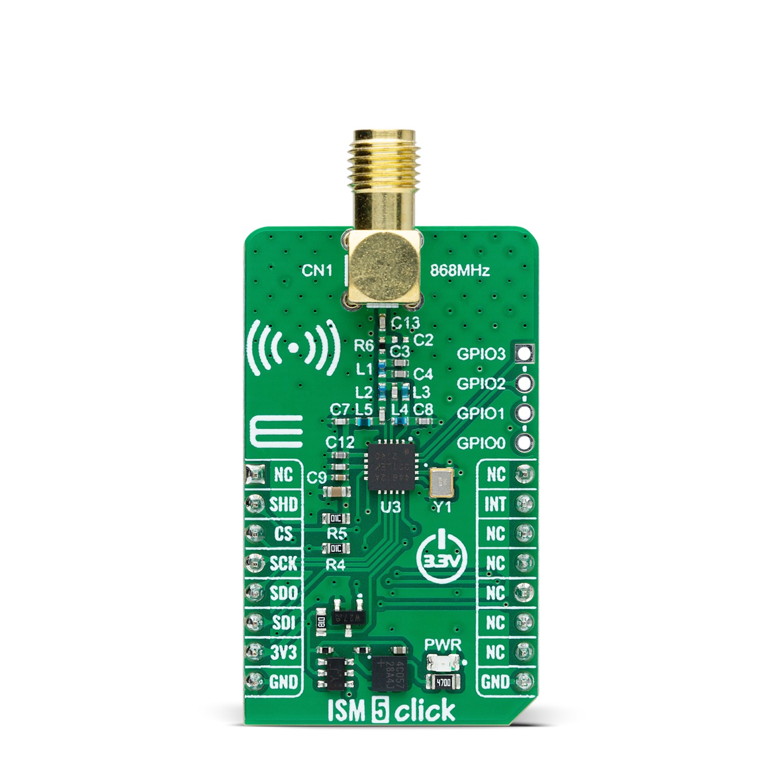
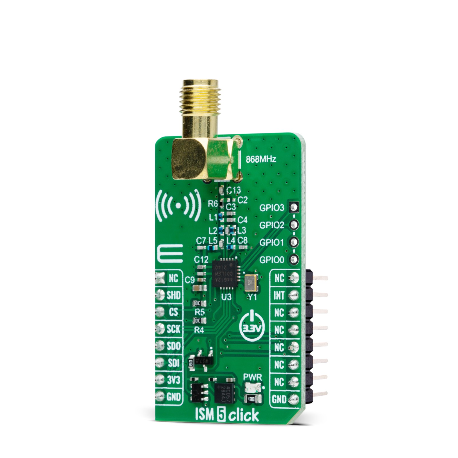
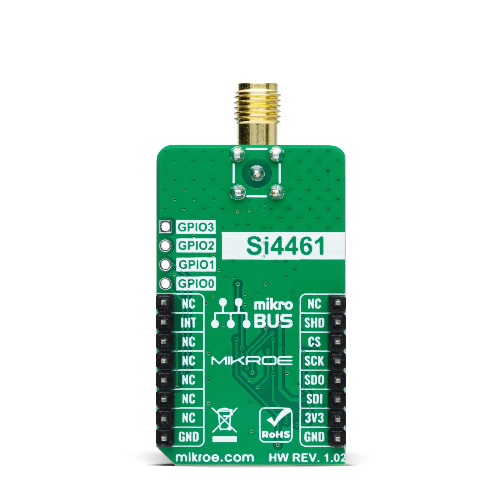
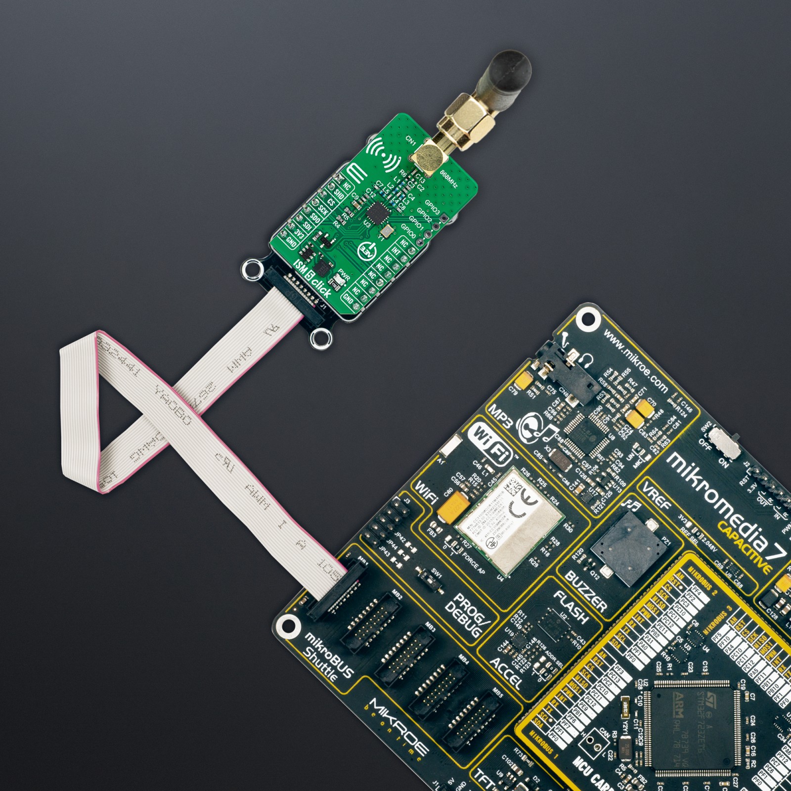
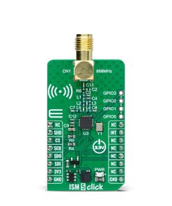
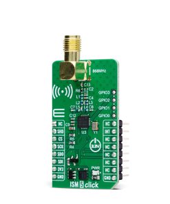
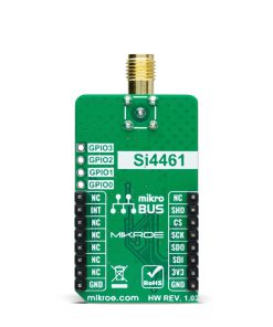
ISM 5 Click is based on the Si4461, a high-performance, low-current transceiver from Silicon Labs made for the Sub-GHz 868MHz frequency band. This high-performance component is designed for efficient operation in the time division duplexing (TDD) mode, seamlessly alternating between transmitting and receiving data packets. It supports a broad range of modulations, including (G)FSK, 4(G)FSK, (G)MSK, and OOK, and uses a single-conversion mixer to downconvert signals modulated by FSK/GFSK or OOK to a low intermediate frequency (IF). A programmable gain amplifier (PGA) enhances the signal before a high-performance ADC digitizes it, enabling the built-in digital signal processor (DSP) to handle filtering, demodulation, slicing, and packet management. This digital approach enhances receiver flexibility and performance compared to traditional analog systems. The demodulated data is accessible to the host MCU through a configurable GPIO on an unpopulated header or via a standard SPI bus using a 64-byte RX FIFO.
Key specifications of the Si4461 include its exceptional receive sensitivity of -129dBm and maximum output power of -16dBm. It boasts low active power consumption with ultra-low current modes with 30nA in Shutdown and 40nA in Standby. The device’s synthesizer supports variable data rates from 100bps up to 1Mbps, complemented by rapid wake and hop times and a highly versatile packet handler that autonomously manages nearly any packet structure. Its dual 64-byte FIFOs for TX and RX streamline data management, making it ideal for applications such as smart metering, home security systems, remote control, telemetry, home automation, industrial control, and sensor networks.
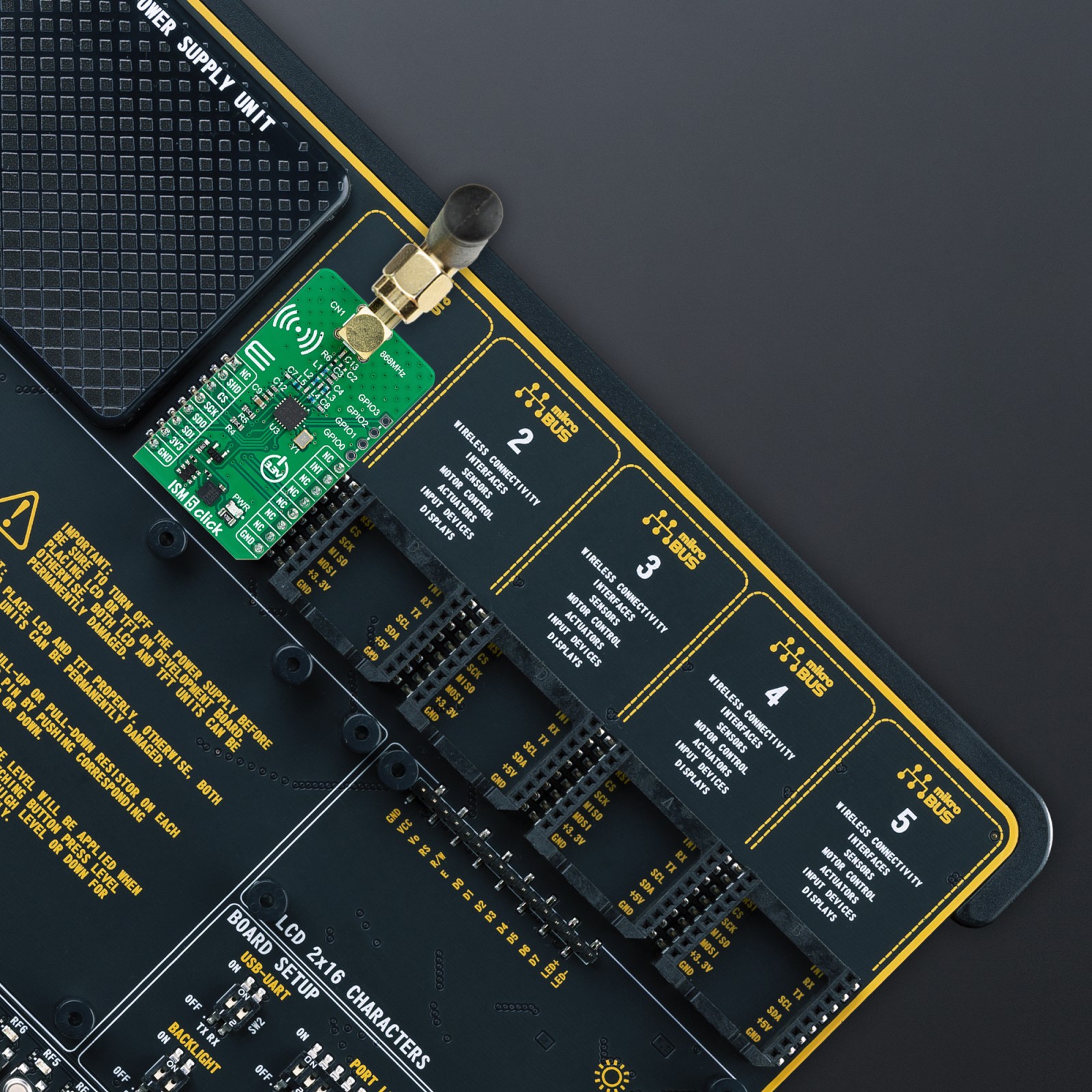
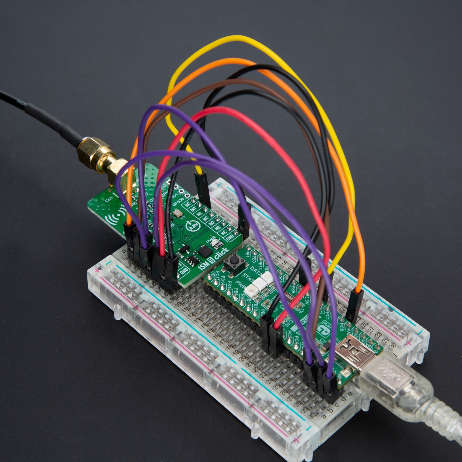
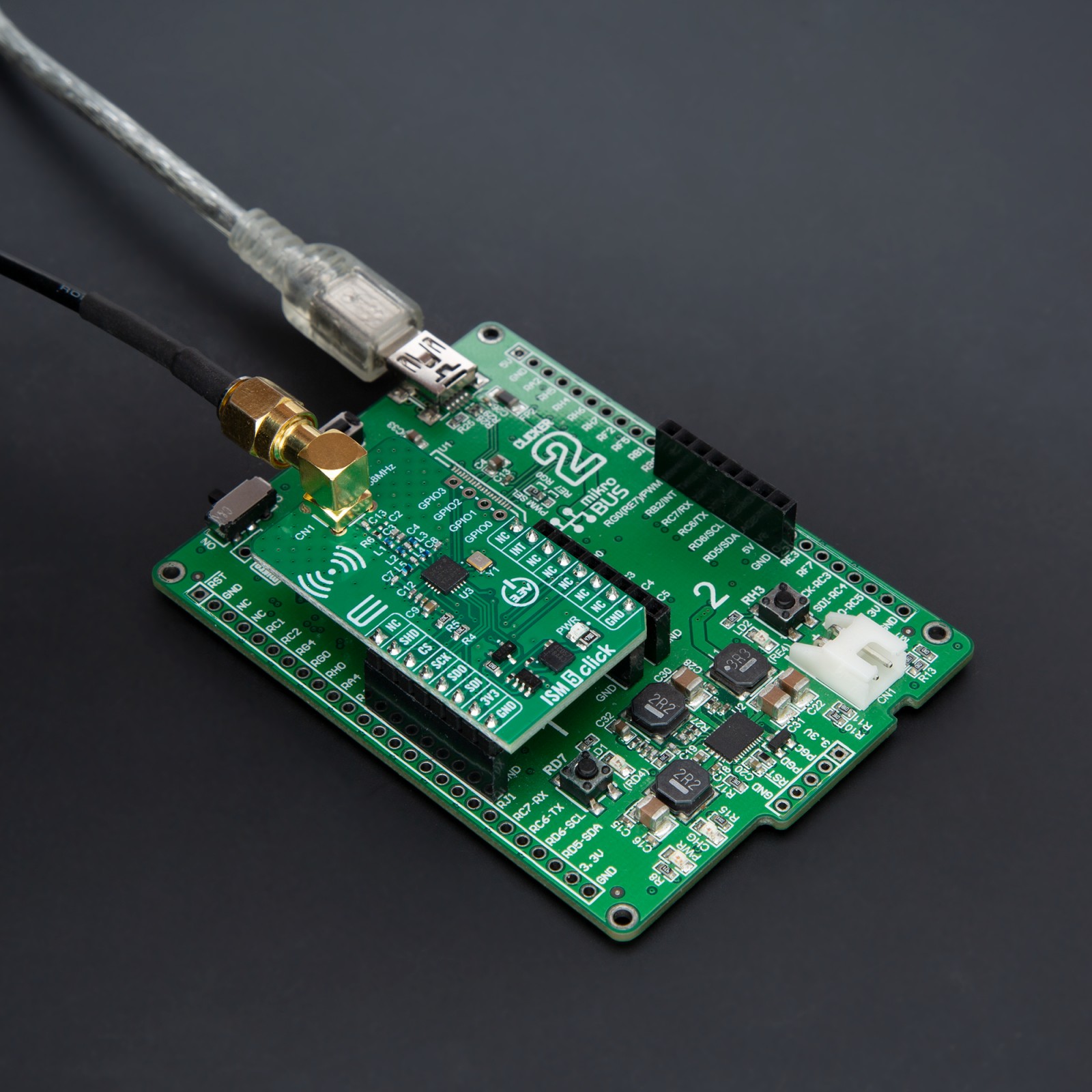
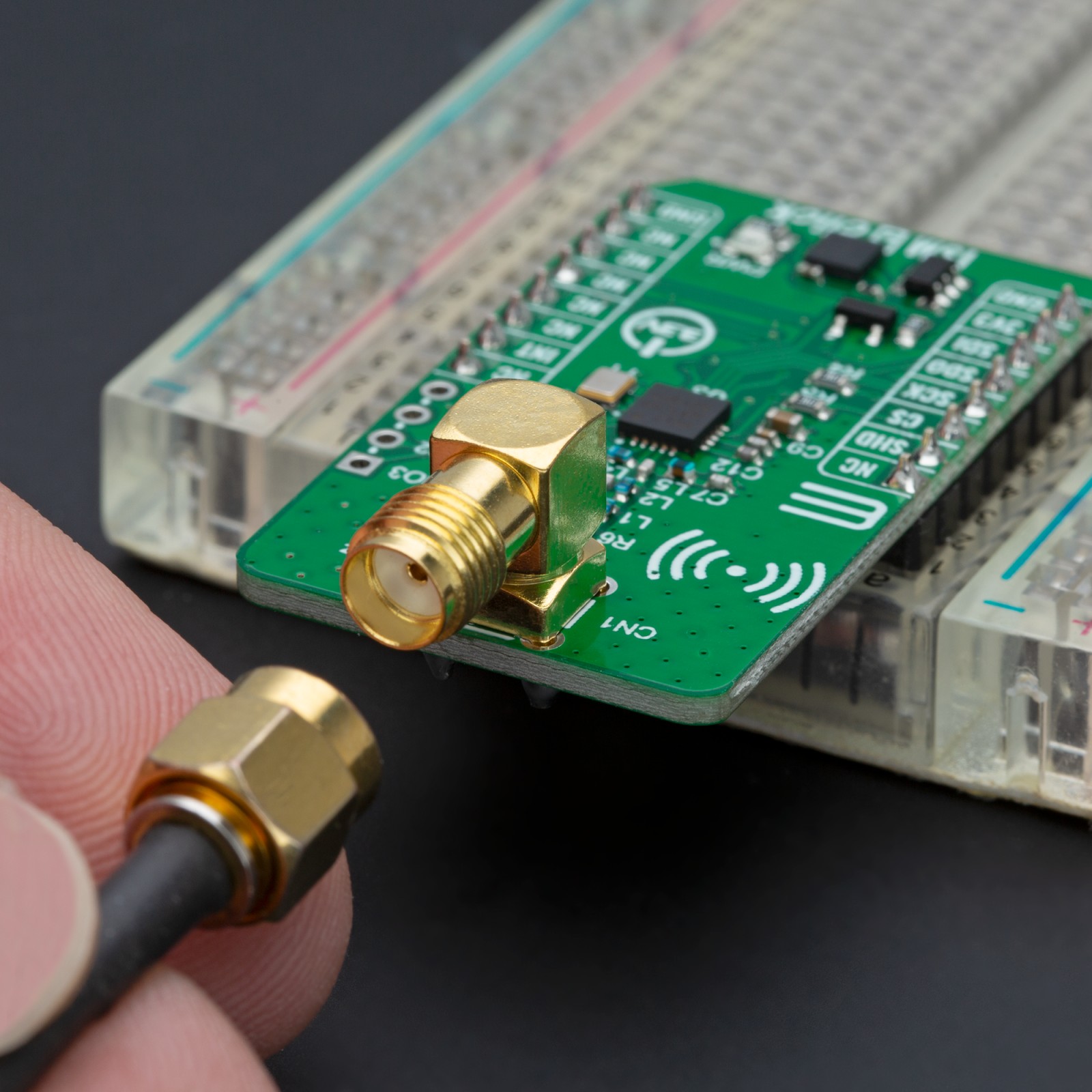
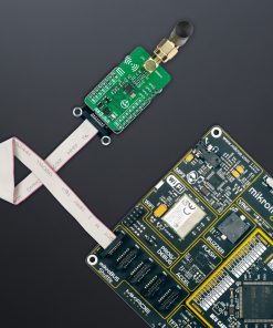
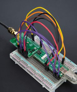
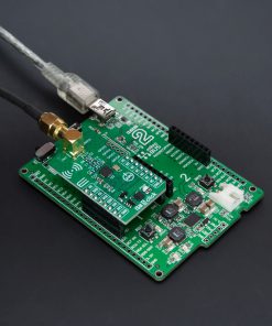
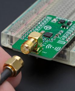
As mentioned, the ISM 5 Click communicates with the host MCU through a standard 4-wire SPI, capable of up to 10MHz operational frequency. It also features a Shutdown mode for minimal power consumption, activated by setting the SDN pin of the mikroBUS™ socket high, and an interrupt capability, the INT pin of the mikroBUS™ socket, to signal the MCU upon specific events by setting this pin in a LOW logic state. This functionality ensures efficient power management and responsive system behavior. Moreover, the ISM 5 Click includes an SMA antenna connector for connecting a Rubber Right Angle 868MHz Antenna for optimal performance, available through the MIKROE shop.
This Click board™ can be operated only with a 3.3V logic voltage level. The board must perform appropriate logic voltage level conversion before using MCUs with different logic levels. Also, it comes equipped with a library containing functions and an example code that can be used as a reference for further development.
Specifications
Type
Sub-1 GHz Transceievers
Applications
Ideal for smart metering, home security, remote control, telemetry, and industrial control, offering developers a powerful tool for building advanced, energy-efficient wireless solutions
On-board modules
Si4461 – high-performance low-current transceiver from Silicon Labs
Key Features
Multiple modulation support, exceptional receive sensitivity, low power consumption, adjustable data rates, made for 868MHz frequency band, advanced packet handling, 64-byte FIFOs, SPI interface, shutdown and interrupt feature, and more
Interface
SPI
Feature
ClickID
Compatibility
mikroBUS™
Click board size
M (42.9 x 25.4 mm)
Input Voltage
3.3V
Pinout diagram
This table shows how the pinout on ISM 5 Click corresponds to the pinout on the mikroBUS™ socket (the latter shown in the two middle columns).
Onboard settings and indicators
Label | Name | Default | Description |
---|---|---|---|
LD1 | PWR | – | Power LED Indicator |
ISM 5 Click electrical specifications
Description | Min | Typ | Max | Unit |
---|---|---|---|---|
Supply Voltage | – | 3.3 | – | V |
Frequency Range | – | 868 | – | MHz |
Data Rate | – | – | 1 | Mbps |
Output Power | – | – | -16 | dBm |
Software Support
We provide a library for the ISM 5 Click as well as a demo application (example), developed using MIKROE compilers. The demo can run on all the main MIKROE development boards.
Package can be downloaded/installed directly from NECTO Studio Package Manager (recommended), downloaded from our LibStock™ or found on Mikroe github account.
Library Description
This library contains API for ISM 5 Click driver.
Key functions
-
ism5_get_part_info
This function reads the device part information. -
ism5_transmit_packet
This function transmits a desired data packet on the selected channel. -
ism5_receive_packet
This function waits for a data packet to arrive on the selected channel and reads it.
Example Description
This example demonstrates the use of an ISM 5 Click board™ by showing the communication between the two click boards (Server and Client).
void application_task ( void )
{
err_t error_flag = ISM5_OK;
static uint16_t packet_cnt = 0;
uint8_t data_buf[ ISM5_PACKET_MAX_SIZE ] = { 0 };
#ifdef DEMO_APP_SERVER
log_printf ( &logger, " Waiting for a packet message from client device...rn" );
error_flag = ism5_receive_packet ( &ism5, CHANNEL_NUMBER, data_buf, NULL, ISM5_PACKET_TIMEOUT_DISABLE );
if ( ISM5_OK == error_flag )
{
packet_cnt = ( ( uint16_t ) data_buf[ 0 ] << 8 ) | data_buf[ 1 ];
log_printf ( &logger, " Packet #%u is received with message: %srn", packet_cnt, &data_buf[ 2 ] );
Delay_ms ( 200 );
log_printf ( &logger, " Server transmits an acknowledge message to client for packet #%urnn", packet_cnt );
error_flag = ism5_transmit_packet ( &ism5, CHANNEL_NUMBER, ACKNOWLEDGE_RESPONSE, strlen ( ACKNOWLEDGE_RESPONSE ) );
}
#else
if ( ( strlen ( TEXT_MESSAGE_TO_SEND ) + 2 ) > ISM5_PACKET_MAX_SIZE )
{
log_error( &logger, " Packet exceeds maximal allowable length." );
error_flag = ISM5_ERROR;
}
if ( ISM5_OK == error_flag )
{
data_buf[ 0 ] = ( uint8_t ) ( ( packet_cnt >> 8 ) & 0xFF );
data_buf[ 1 ] = ( uint8_t ) ( packet_cnt & 0xFF );
memcpy ( &data_buf[ 2 ], TEXT_MESSAGE_TO_SEND, strlen ( TEXT_MESSAGE_TO_SEND ) );
log_printf ( &logger, " Client transmits packet #%u to serverrn", packet_cnt );
error_flag = ism5_transmit_packet ( &ism5, CHANNEL_NUMBER, data_buf, strlen ( TEXT_MESSAGE_TO_SEND ) + 2 );
}
if ( ISM5_OK == error_flag )
{
log_printf ( &logger, " Waiting for an acknowledge...rn" );
error_flag = ism5_receive_packet ( &ism5, CHANNEL_NUMBER, data_buf, NULL, ISM5_PACKET_TIMEOUT_1_SEC );
}
if ( ( ISM5_OK == error_flag ) && ( strstr ( data_buf, ACKNOWLEDGE_RESPONSE ) ) )
{
log_printf ( &logger, " Acknowledge message is received from server!rnn" );
packet_cnt++;
}
else
{
log_printf ( &logger, " Acknowledge message is NOT received from server!rnn" );
}
Delay_ms ( 1000 );
}
The full application code, and ready to use projects can be installed directly from NECTO Studio Package Manager (recommended), downloaded from our LibStock™ or found on Mikroe github account.
Other Mikroe Libraries used in the example:
- MikroSDK.Board
- MikroSDK.Log
- Click.ISM5
Additional notes and informations
Depending on the development board you are using, you may need USB UART click, USB UART 2 Click or RS232 Click to connect to your PC, for development systems with no UART to USB interface available on the board. UART terminal is available in all MIKROE compilers.
mikroSDK
This Click board™ is supported with mikroSDK – MIKROE Software Development Kit. To ensure proper operation of mikroSDK compliant Click board™ demo applications, mikroSDK should be downloaded from the LibStock and installed for the compiler you are using.
For more information about mikroSDK, visit the official page.