NeoMesh 2 Click
R1,150.00 ex. VAT
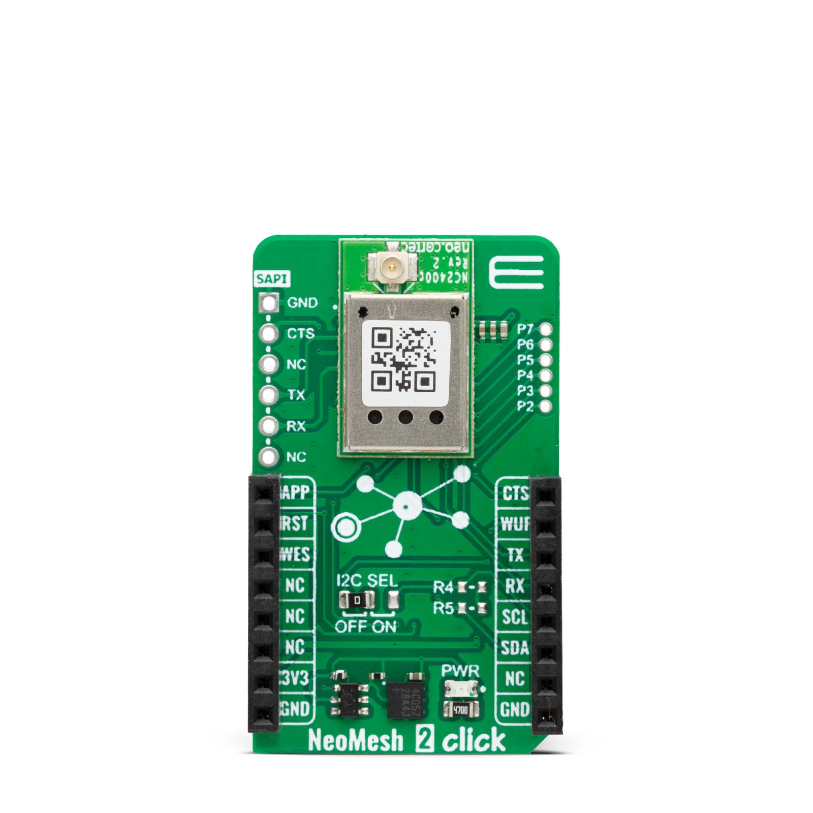
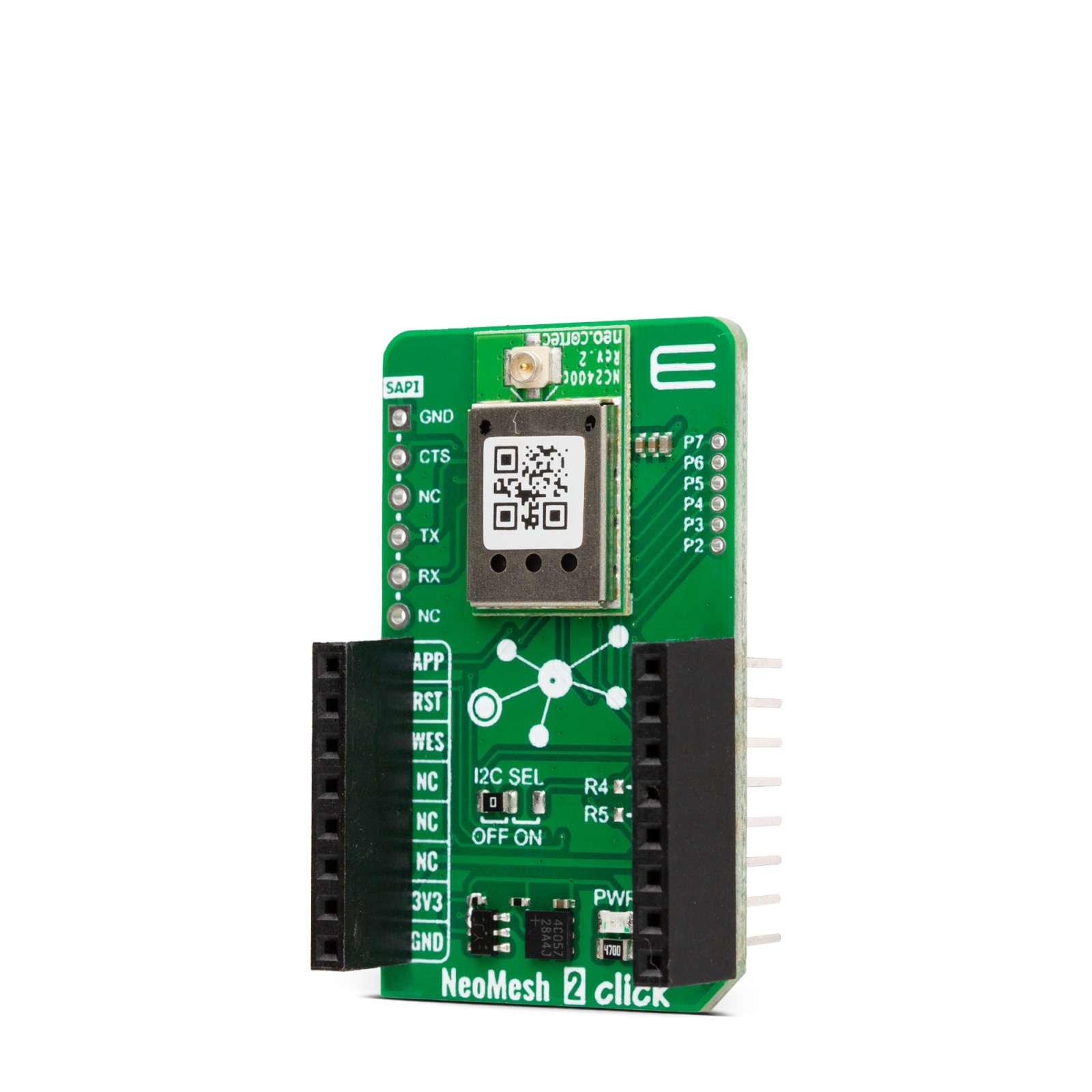
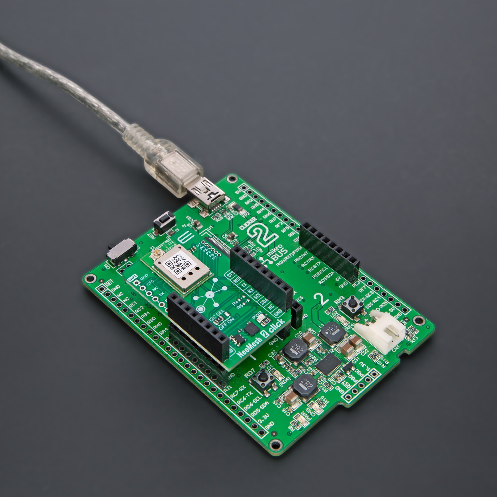
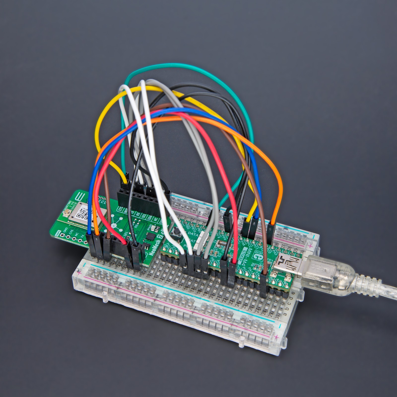
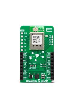
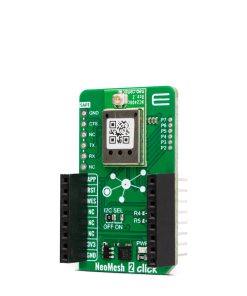
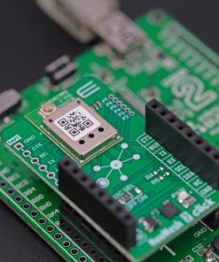
NeoMesh 2 Click is a compact add-on board with a low-power, long-range transceiver, ideal for Mesh wireless networking. This board features the NC2400, a wireless Mesh network module from NeoCortec. With an additional antenna that MIKROE offers connected to the module’s u.Fl connector, you can create a fully functional wireless Mesh network node that will work in the frequency band of 2.4GHz. The module has a generic application layer that can be configured to suit applications. This Click board™ makes the perfect solution for the development of wireless sensor networks, automatic meter reading, advanced metering architecture, industrial automation, agricultural and forest monitoring, and more.
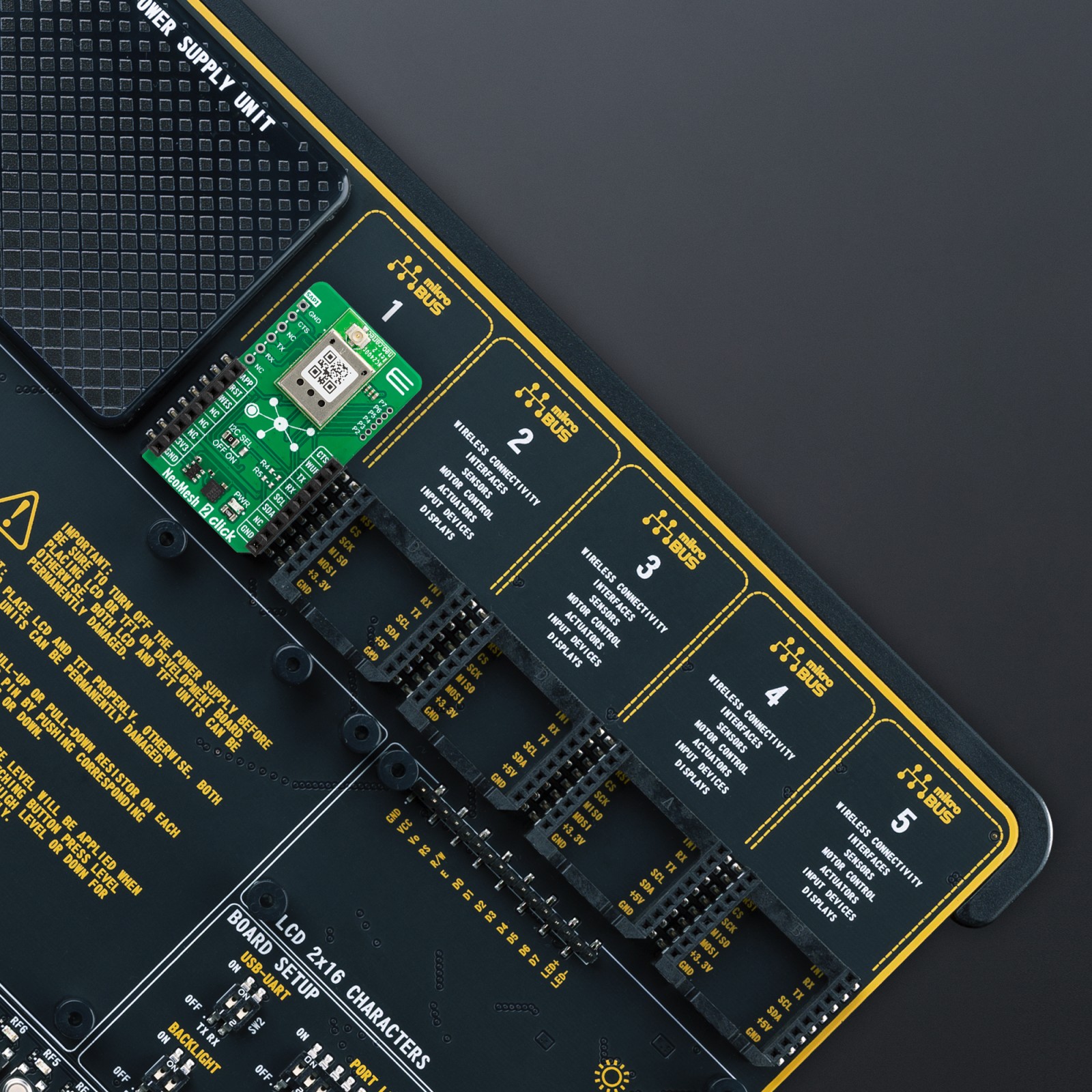
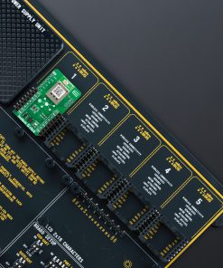
NeoMesh 2 Click is fully compatible with the mikroBUS™ socket and can be used on any host system supporting the mikroBUS™ standard. It comes with the mikroSDK open-source libraries, offering unparalleled flexibility for evaluation and customization. What sets this Click board™ apart is the groundbreaking ClickID feature, enabling your host system to seamlessly and automatically detect and identify this add-on board.
Stock: Lead-time applicable.
| 5+ | R1,092.50 |
| 10+ | R1,035.00 |
| 15+ | R977.50 |
| 20+ | R940.70 |
How does it work?
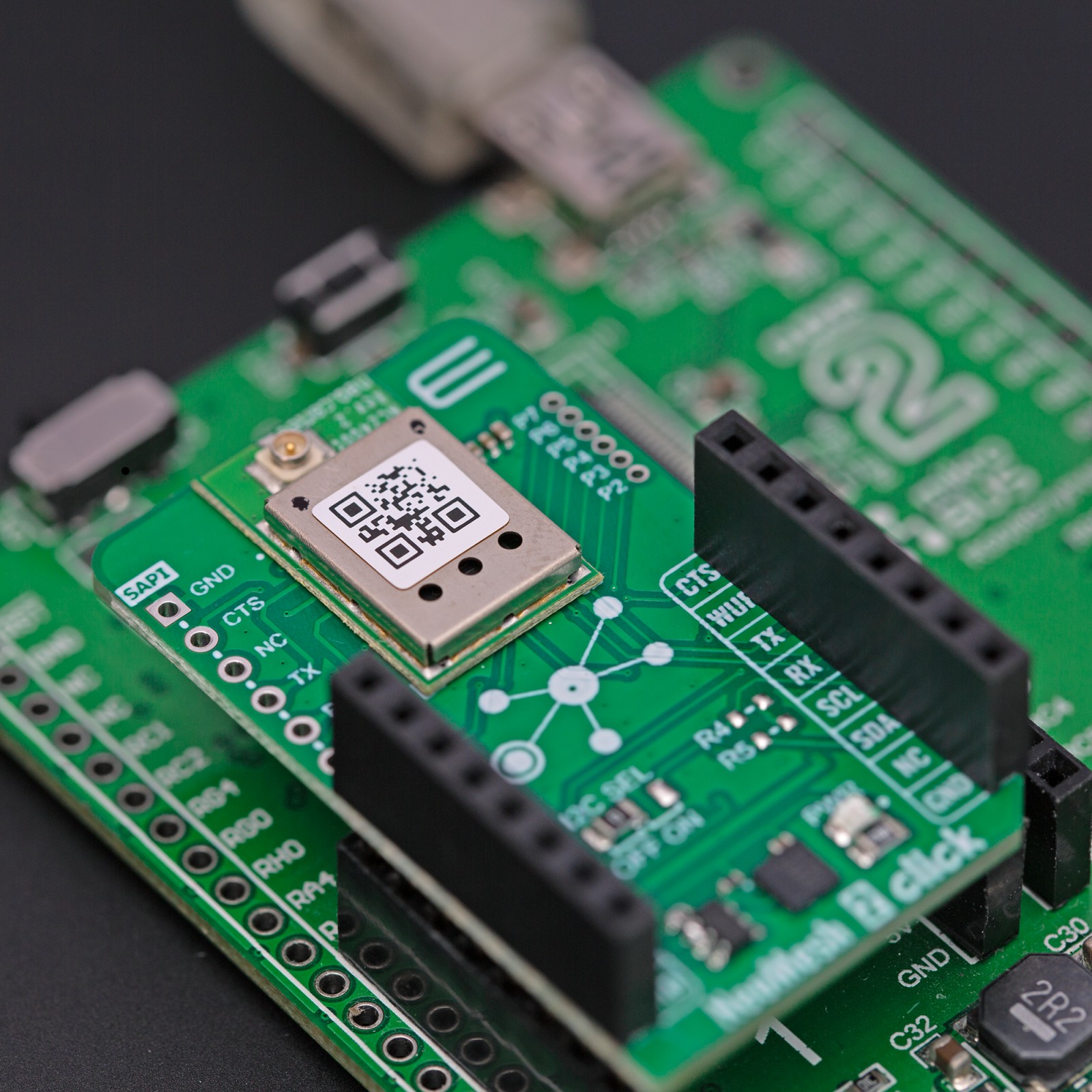
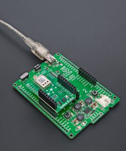
NeoMesh 2 Click is based on the NC2400, a wireless Mesh network module from NeoCortec. Besides being controlled by the host MCU, NeoMesh 2 Click can be used as a standalone device. You can configure the module over the System API (SAPI), a UART-based interface with hardware flow control. This interface is configured to ensure direct compatibility with the FTDI serial to USB cable. When using the NeoMesh 2 Click as a standalone board, the application interface of the NeoMesh module can be easily accessed through the pin header located at the side of the module. There are eight pins, six in the header labeled P2-7, which allows you to use up to 6 channels of 12-bit ADC, GPIOs, I2C sensors, and UART application APIs. Specific pins of this header can be used to interface with an external microcontroller through UART.

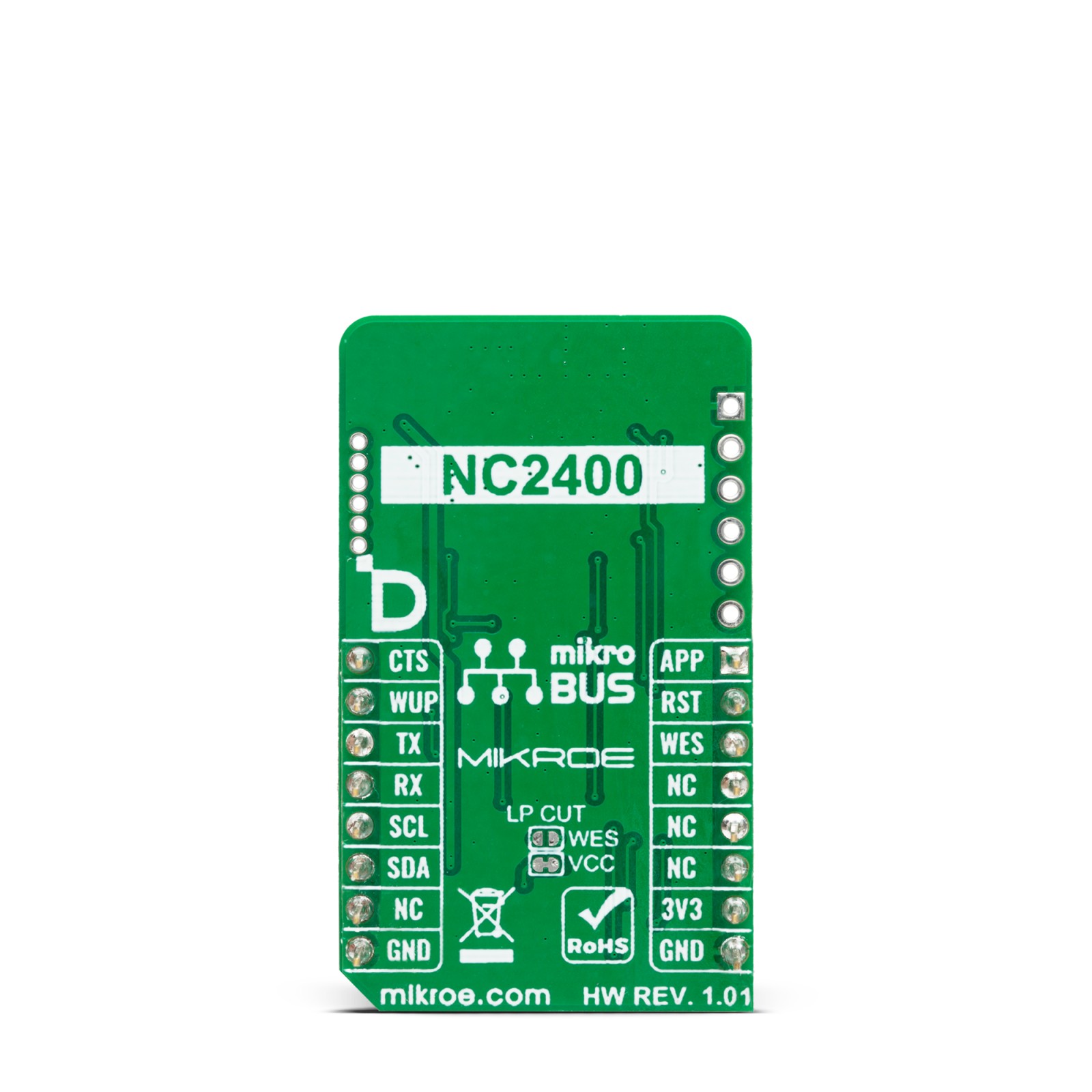
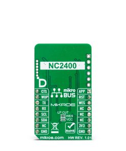
The module also can be configured wirelessly. At the bottom side, there is an unconnected WES jumper. You can use the Wireless Encrypted Setup by connecting it, but only if it is already configured through the WES procedure. Every WES channel has a specified AES 128 encryption key. Just beside is another jumper, VCC, this one connected. The NeoMesh 2 Click is optimized for ultra-low power operation and allows operation on small batteries for several years. If you want to make an ultra-low power node, consider using the NeoMesh 2 Click with some low-power development board with battery management, such as the Clicker 2 series or something similar. This scenario is ideal where the node can send data infrequently and the payload size is small.
NeoMesh is a wireless system designed with versatility in mind, allowing users to build products in many different application areas. This system can handle data transmission, lost neighbor nodes, moving nodes, and more. Data transmission through the network is done sequentially from node to node until the data reaches its destination. There are three types of NeoMesh devices: coordinator, router, and end device. You can configure your device according to your needs.
NeoMesh 2 Click uses a standard UART serial interface to communicate with the host MCU, with commonly used UART RX and TX pins and a transfer speed of 115200bps. Hardware control flow is available through the CTS pin. You can also use an I2C interface as a virtual UART. The I2C interface can be enabled over the I2C SEL jumper. While disabled, you can use the WUP pin to indicate the WakeUp activity state of the module; otherwise, the WUP function is unavailable. The module can be reset over the RST pin. The generic application activity is indicated over the APP pin with logic Low state when active. If the Wireless Encrypted Setup JP2 jumper is closed, you can enable the WES client over the WES pin.
The board features one u.Fl connector for the main LTE antenna that MIKROE offers, like the WiFi 2.4GHz/5.4GHz Active FPC Antenna for efficient connectivity.
This Click board™ can be operated only with a 3.3V logic voltage level. The board must perform appropriate logic voltage level conversion before using MCUs with different logic levels. Also, it comes equipped with a library containing functions and an example code that can be used as a reference for further development.
Specifications
Type
2.4 GHz Transceivers,Mesh Network
Applications
Can be used for the development of wireless sensor networks, automatic meter reading, advanced metering architecture, industrial automation, agricultural and forest monitoring, and more
On-board modules
NC2400 – a wireless Mesh network module from NeoCortec
Key Features
Full system in module, fully functional wireless Mesh network node, generic application layer which can be configured to suit product needs, NeoMesh protocol stack optimized for ultra-low power and reliability, and more
Interface
I2C,UART
Feature
ClickID
Compatibility
mikroBUS™
Click board size
M (42.9 x 25.4 mm)
Input Voltage
3.3V
Pinout diagram
This table shows how the pinout on NeoMesh 2 Click corresponds to the pinout on the mikroBUS™ socket (the latter shown in the two middle columns).
Onboard settings and indicators
| Label | Name | Default | Description |
|---|---|---|---|
| LD1 | PWR | – | Power LED Indicator |
| JP1 | VCC | Closed | Low-power application usage when opened |
| JP2 | WES | Open | Wireless Encryption Setup enabled when closed |
| JP3 | I2C SEL | Left | I2C Interface Selection OFF/ON: Left position OFF, Right position ON |
NeoMesh 2 Click electrical specifications
| Description | Min | Typ | Max | Unit |
|---|---|---|---|---|
| Supply Voltage | – | 3.3 | – | V |
| Operating Frequency | – | 2400 | – | MHz |
| Output Power | -30 | – | +1 | dBm |
Software Support
We provide a library for the NeoMesh 2 Click as well as a demo application (example), developed using MIKROE compilers. The demo can run on all the main MIKROE development boards.
Package can be downloaded/installed directly from NECTO Studio Package Manager (recommended), downloaded from our LibStock™ or found on Mikroe github account.
Library Description
This library contains API for NeoMesh 2 Click driver.
Key functions
-
neomesh2_send_aapi_frameThis function sends a desired AAPI frame by using UART serial interface. -
neomesh2_read_aapi_frameThis function reads an AAPI frame by using UART serial interface. -
neomesh2_send_sapi_frameThis function sends a desired SAPI frame by using UART serial interface.
Example Description
This example demonstrates the use of NeoMesh 2 Click board™ by showing the communication between the two click boards.
void application_task ( void )
 {
 #if ( DEMO_APP == APP_ORIGINATOR )
     log_printf( &logger, "rn Send message to node: %.4Xrn", ( uint16_t ) NODE_ID_RECEIVER_1 );
     aapi_frame.cmd = NEOMESH2_CMD_ACK_SEND;
     aapi_frame.len = 3 + strlen ( DEMO_TEXT_MESSAGE );
     aapi_frame.payload[ 0 ] = ( uint8_t ) ( ( NODE_ID_RECEIVER_1 >> 8 ) & 0xFF );
     aapi_frame.payload[ 1 ] = ( uint8_t ) ( NODE_ID_RECEIVER_1 & 0xFF );
     aapi_frame.payload[ 2 ] = DEFAULT_PORT;
     strcpy ( &aapi_frame.payload[ 3 ], DEMO_TEXT_MESSAGE );
     if ( NEOMESH2_OK == neomesh2_send_aapi_frame ( &neomesh2, &aapi_frame ) )
     {
         neomesh2_parse_aapi_rsp ( NEOMESH2_RSP_ACK );
     }
     #ifndef SINGLE_RECEIVER_MODE
         log_printf( &logger, "rn Send message to node: %.4Xrn", ( uint16_t ) NODE_ID_RECEIVER_2 );
         aapi_frame.cmd = NEOMESH2_CMD_ACK_SEND;
         aapi_frame.len = 3 + strlen ( DEMO_TEXT_MESSAGE );
         aapi_frame.payload[ 0 ] = ( uint8_t ) ( ( NODE_ID_RECEIVER_2 >> 8 ) & 0xFF );
         aapi_frame.payload[ 1 ] = ( uint8_t ) ( NODE_ID_RECEIVER_2 & 0xFF );
         aapi_frame.payload[ 2 ] = DEFAULT_PORT;
         strcpy ( &aapi_frame.payload[ 3 ], DEMO_TEXT_MESSAGE );
         if ( NEOMESH2_OK == neomesh2_send_aapi_frame ( &neomesh2, &aapi_frame ) )
         {
             neomesh2_parse_aapi_rsp ( NEOMESH2_RSP_ACK );
         }
     #endif
 #else
    neomesh2_parse_aapi_rsp ( NULL );
 #endif
 }
The full application code, and ready to use projects can be installed directly from NECTO Studio Package Manager (recommended), downloaded from our LibStock™ or found on Mikroe github account.
Other Mikroe Libraries used in the example:
- MikroSDK.Board
- MikroSDK.Log
- Click.NeoMesh2
Additional notes and informations
Depending on the development board you are using, you may need USB UART click, USB UART 2 Click or RS232 Click to connect to your PC, for development systems with no UART to USB interface available on the board. UART terminal is available in all MikroElektronika compilers.
mikroSDK
This Click board™ is supported with mikroSDK – MikroElektronika Software Development Kit. To ensure proper operation of mikroSDK compliant Click board™ demo applications, mikroSDK should be downloaded from the LibStock and installed for the compiler you are using.
For more information about mikroSDK, visit the official page.
Resources
Downloads
| Weight | 19 g |
|---|---|
| Brand | MikroElektronika |

