How does it work?
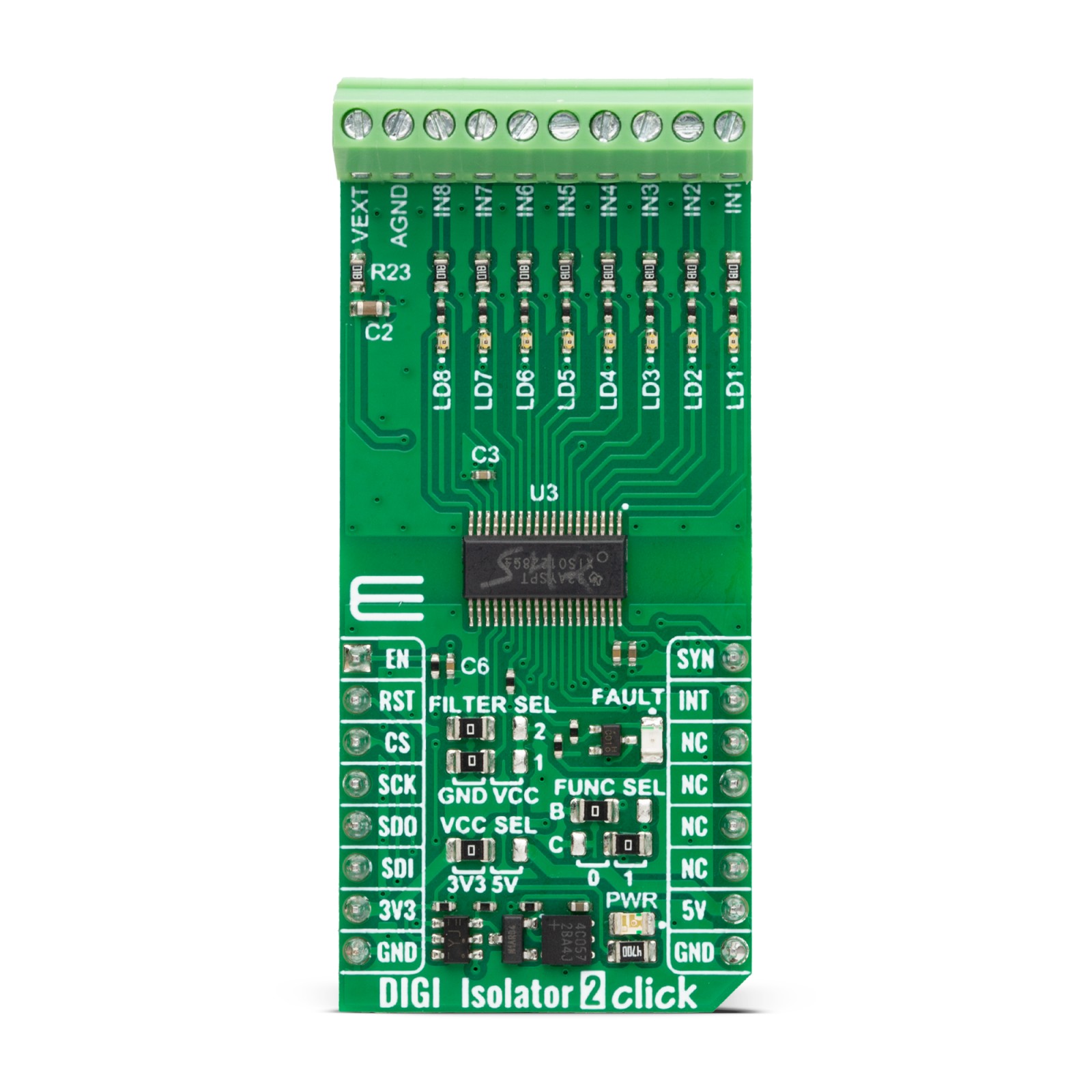
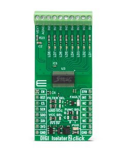
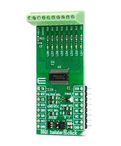
DIGI Isolator 2 Click is based on the ISO1228, an eight-channel isolated digital input from Texas Instruments. The ISO1228 on this Click board™ is configured in sinking type of inputs. The current drawn from the digital inputs is diverted to LEDs once the digital input crosses the input voltage threshold. This feature allows field-side LED indication with no additional power consumption. The field supply voltage ranges from 8.5 up to 36V, and besides digital inputs, it can be connected over the screw terminals. The isolator also features wire-break detection, an integrated field supply voltage monitor, a built-in CRC check across the barrier, and more.
There are several settings that you can make on DIGI Isolator 2 Click. The ISO1228 supports built-in digital low-pass filters, which the software can program. You can also program it over two FILTER SEL jumpers, which support three input states (high, low, float), resulting in 9 values. Software settings will override those on FILTER SEL. The isolator will turn the FAULT LED on if a fault condition occurs.
DIGI Isolator 2 Click can use a standard 4-wire SPI serial interface to communicate with the host MCU, supporting clock frequencies of up to 25MHz. While using the SPI interface, you can reset the device over the RST pin and control the enable function over the EN pin. Whenever the data on inputs of the isolator changes, the interrupt INT pin will go Low. Whenever the information for the synchronization with the host MCU is transmitted, the SYN pin will be asserted High. The SPI interface supports the Burst mode, which can be selected over the FUNC SEL B jumper.
You can also use a parallel interface where the four SPI pins, along with the RST, SYN, and INT, will act as standard general-purpose inputs (isolator outputs). The OUT7 of the ISO1228 is also used as a Burst mode jumper. In parallel mode, you should let the FUNC SEL B jumper float. Furthermore, you can’t use the input 6 of the DIGI Isolator 2 Click board™. The selection of communication can be made over the FUNC SEL C jumper.
This Click board™ can operate with either 3.3V or 5V logic voltage levels selected via the VCC SEL jumper. This way, both 3.3V and 5V capable MCUs can use the communication lines properly. Also, this Click board™ comes equipped with a library containing easy-to-use functions and an example code that can be used as a reference for further development.
Specifications
Type
Isolators,Port expander
Applications
Can be used for the development of programmable logic controllers (PLC), digital input modules, and more
On-board modules
ISO1228 – eight-channel isolated digital input from Texas Instruments.
Key Features
Eight isolated digital inputs, low power, and heat dissipation, wire-break detection, integrated field supply voltage monitor, SPI burst mode, parallel mode, integrated IEC ESD and surge protection, wide field supply voltage range, and more
Interface
SPI
Feature
ClickID
Compatibility
mikroBUS™
Click board size
L (57.15 x 25.4 mm)
Input Voltage
3.3V or 5V,External
Pinout diagram
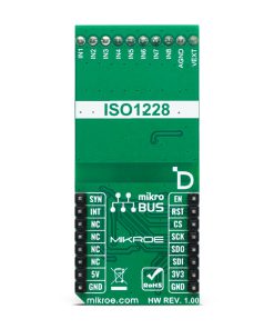
This table shows how the pinout on DIGI Isolator 2 Click corresponds to the pinout on the mikroBUS™ socket (the latter shown in the two middle columns).
Onboard settings and indicators
Label | Name | Default | Description |
---|---|---|---|
LD1-LD8 | LD1-LD8 | – | Input LED Indicators |
LD9 | FAULT | – | Fault LED Indicator |
LD10 | PWR | – | Power LED Indicator |
JP1 | VCC SEL | Left | Logic Level Voltage Selection 3V3/5V: Left position 3V3, Right position 5V |
JP2-JP3 | FILTER SEL | Left | Digital Filter Selection GND/VCC: Left position GND, Right position VCC |
JP4 | FUNC SEL C | Right | Communication Interface Selection 0/1: Left position 0, Right position 1 |
JP5 | FUNC SEL B | Left | Burst Mode Selection 0/1: Left position 0, Right position 1 |
DIGI Isolator 2 Click electrical specifications
Description | Min | Typ | Max | Unit |
---|---|---|---|---|
Supply Voltage | 3.3 | – | 5 | V |
Field Supply Voltage Range | 8.5 | – | 36 | V |
Maximum Withstand Isolation Voltage | – | 3 | – | kVrms |
Data Rate | – | – | 1.5 | Mbps |
Software Support
We provide a library for the DIGI Isolator 2 Click as well as a demo application (example), developed using MikroElektronika compilers. The demo can run on all the main MikroElektronika development boards.
Package can be downloaded/installed directly from NECTO Studio Package Manager(recommended way), downloaded from our LibStock™ or found on Mikroe github account.
Library Description
This library contains API for DIGI Isolator 2 Click driver.
Key functions
-
digiisolator2_enable_output
This function enables output by setting the EN pin to high state. -
digiisolator2_disable_output
This function disables output by setting the EN pin to low state. -
digiisolator2_read_inputs
This function reads all inputs state via the selected driver interface.
Example Description
This example demonstrates the use of DIGI Isolator 2 click board by reading and displaying the state of 8 digital input channels.
void application_task ( void )
{
uint8_t input_data = 0;
if ( DIGIISOLATOR2_OK == digiisolator2_read_inputs ( &digiisolator2, &input_data ) )
{
log_printf( &logger, " INPUT: 0x%.2Xrnn", ( uint16_t ) input_data );
Delay_ms ( 500 );
}
}
The full application code, and ready to use projects can be installed directly from NECTO Studio Package Manager(recommended way), downloaded from our LibStock™ or found on Mikroe github account.
Other Mikroe Libraries used in the example:
- MikroSDK.Board
- MikroSDK.Log
- Click.DIGIIsolator2
Additional notes and informations
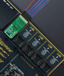
Depending on the development board you are using, you may need USB UART click, USB UART 2 Click or RS232 Click to connect to your PC, for development systems with no UART to USB interface available on the board. UART terminal is available in all MikroElektronika compilers.
mikroSDK
This Click board™ is supported with mikroSDK – MikroElektronika Software Development Kit. To ensure proper operation of mikroSDK compliant Click board™ demo applications, mikroSDK should be downloaded from the LibStock and installed for the compiler you are using.
For more information about mikroSDK, visit the official page.